Transcription
Fusion 360 Electronics Migration Guide for EAGLE UsersJuly 2022
Fusion Electronics Migration Guide for EAGLE usersTable of Contents1Introduction-4-2Where Are my Fusion 360 Files Stored?-4-3Organize your Electronics Projects in Fusion-5-Create Projects in Fusion-5-Start a new Electronics Design-6-Projects and FoldersBrand-new Design with a New SchematicBring Your EAGLE Design into Fusion-7-8-8-Save your files in Fusion- 10 -Share Projects- 11 -4Maximize your editing workspace in Fusion 360 Electronics- 12 -5Work with Multiple Windows and Monitors- 14 -6Where are my Fusion 360 settings and preferences?- 15 -7Menus and settings in Schematic and 2D PCB- 16 -Schematic Editor- 16 -2D PCB Editor- 20 -Command shortcuts- 23 -DESIGN menuDOCUMENT menuVALIDATE menuAUTOMATE menuLIBRARY menuQuick Access toolbar- 17 - 18 - 18 - 19 - 19 - 19 -DESIGN menuDOCUMENT menuRULES ERC/DRC menuMANUFACTURING menuAUTOMATION menuSIMULATION menuLIBRARY menu- 20 - 21 - 21 - 22 - 22 - 22 - 23 -Fusion Default AssignmentElectronics-specific Command Assignment- 23 - 25 -8User Language Programs and Scripts in Fusion 360 Electronics- 26 -9Use Your Eagle Libraries and Manage Libraries in Fusion 360- 27 -Library Manager- 27 -Filtering optionsWhy are there libraries at different locations?What are the library sources?10- 28 - 29 - 29 -First use of the Library Editor- 29 -Create New Library- 29 -Edit a Managed Library Created in EAGLE- 30 -Import Libraries- 32 -Content Manager in the Library Editor- 32 2
Fusion Electronics Migration Guide for EAGLE usersLibrary Editor Overview- 33 -Device Editor- 36 -Symbol Editor- 38 -Footprint Editor- 39 -Package Editor- 40 -CREATE menuImport from Another LibraryMANAGE menu- 34 - 34 - 34 -DEVICE menu- 37 -3
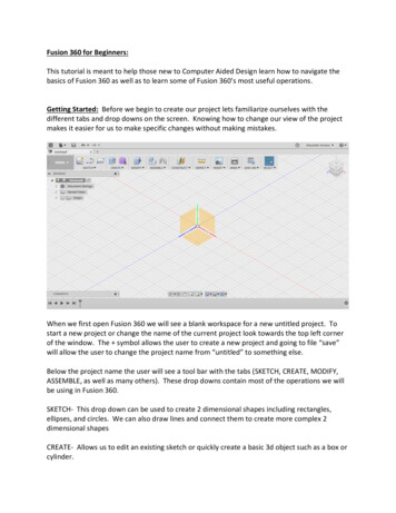
Fusion Electronics Migration Guide for EAGLE users1INTRODUCTIONThis document is designed to give all EAGLE users a hand to safely start with your firststeps in Fusion 360 Electronics. Please follow this guide’s advice for a smooth transitionfrom EAGLE to Fusion Electronics.The move to Fusion 360 offers new options compared to EAGLE- improved and new routing features in the 2D PCB, like Guided Routing, PushObstacles mode with MOVE- new polygon algorithm- easier and tighter 2D/3D collaboration- loop remove and preserve angles in schematic- ODB export- improved library experience- Place Components panelFusion 360 is under constant development and so is the list of new options. Thementioned items are as of May 2022.Additional support can be accessed- in-app product information- in-app self-paced learning content- in-app learning panel- in-app chat to connect with a support agent- Electronics playlist in Autodesk’s Fusion 360 YouTube channel- Autodesk support channel2WHERE ARE MY FUSION 360 FILES STORED?Fusion 360 is a cloud data management product. The electronics project, schematics, 2DPCBs, 3D PCBs, libraries and 3D models are stored in the Autodesk cloud. For moreinformation, see: Where are my Fusion 360 files? al files like scripts, ULPs, CAM jobs, SPICE models are stored on your computer.The Fusion installer creates a Fusion 360 folder with subfolders for ULPs, scripts, designrules, cam files, and spice models in your HOME/Documents folder. This is a good placefor all your user files.In Fusion’s preferences General/Electronics/Directory menu you could adjust the pathswhere these files should be located.-4-
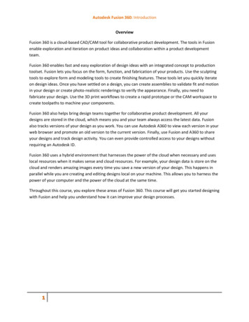
Fusion Electronics Migration Guide for EAGLE users1 Path settings for user files3ORGANIZE YOUR ELECTRONICS PROJECTS IN FUSIONBefore you start working on your electronics projects, think about how youorganize your projects. It’s good practice to create projects for your electronicsdesigns, libraries, and trash. For collaboration you can easily share your projects.CREATE PROJECTS IN FUSIONThe following image shows the data panel with an electronics project named RHElectronics and a Libraries project created and pinnedto the top of the list. A Trashfolder has also been created.Clickin the data panel to create projects for your data.-5-
Fusion Electronics Migration Guide for EAGLE users2 Projects in the data panelProjects to be created:LibrariesUse this project for all library files you created or modified. This will bethe single source of truth of all the libraries you edited.If you plan to collaborate with the mechanical world, it helps to have asubfolder in the Libraries project for all your 3D models.Electronics project nameUse this project for electronics files (in our example: RH-Electronics).You can also save files in subfolders of the project. There you couldfor example keep older versions or variations of your design.TrashDeleting files in Fusion is not always easy. There can be several linkedassets/designs in all the versions of a design and Fusion wants you tounlink all of them before you are allowed to delete. This can betedious. As a quick workaround we use the trash project for files wedon’t need any more. Files moved into the trash project can berestored, if necessary.With a double-click onto one of the project entries in the data panel you dive into projectlevel. To create subfolders, click theicon and name the folder.For the Libraries project you could create a sub-folder named 3D models in case youprefer to have libraries and 3D models in separate locations.START A NEW ELECTRONICS DESIGNIn this section you learn how to create an Electronics Design and then start with anew schematic or reference to an already existing (EAGLE) schematic and board.Before you create your schematic and PCB, you need to create an electronics design file.This is the place where information about the name and location of your current schematicand its related board in 2D and 3D is gathered. It also shows a preview of schematic, 2D-6-
Fusion Electronics Migration Guide for EAGLE usersPCB and 3D PCB in top and bottom view, as soon as available.One schematic refers to one 2D PCB. In comparison to EAGLE, schematic and board canhave different names and can be stored at different locations. Changes in a schematic willbe annotated automatically to the 2D PCB and vice versa. This works the same way asyou are used to in EAGLE.For a flawless annotation between schematic and board, be sure to have both filesopened at the same time.PROJECTS AND FOLDERSBefore you start with the Electronics Design, think about where to save your files and howto organize your projects. It’s good practice to create a New Project first, or a New Folderin an already existing project. This is done in the Fusion data panel. It is best to choose ameaningful name.Click the New Project button and create a new electronics project named Migration Guide.3 Create a New Project in the data panelType the name of the project followed by the enter key. The project has been created now.With a double-click onto the new entry, you navigate into project level.In order to create an electronics design, select File and then pick New Electronics Design.4 Starting a new Electronics DesignNow a new tab with an empty electronics design document opens. From here you startwith your schematic.An Electronics Design file links your schematic and board. This is the only way tomaintain syncing between the schematic and the 2D PCB. Unlike EAGLE, theFusion 360 schematic and the 2D PCB are not required to have the same nameand do not need to be stored in the same folder.-7-
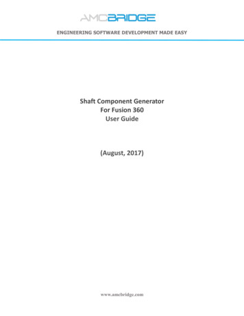
Fusion Electronics Migration Guide for EAGLE usersBRAND-NEW DESIGN WITH A NEW SCHEMATICTo create a new schematic, click the New Schematic icon.5 New Schematic icon in Electronics DesignNow a new tab with the schematic editor opens and shows an empty schematic.6 The schematic editor with a new schematicNext steps:- save your files- start working on your schematicBRING YOUR EAGLE DESIGN INTO FUSIONYou can easily transfer an EAGLE project to Fusion. Click thebutton in the datapanel. In the Upload dialog choose Select files and select the schematic and/or board filesfrom your computer or just drag and drop your files into the dialog.-8-
Fusion Electronics Migration Guide for EAGLE users7 Upload dialog – sch and brd are selected and ready for uploadClick Upload and Fusion gives you Upload Options.8 Upload optionsIf your EAGLE schematic and board files have the same name and are stored in the samefolder, Fusion suggests to automatically create an electronics design file for the selectedfiles. Click OK and copies of your EAGLE files will be automatically uploaded into yourFusion environment into the currently active folder. An Electronics Design file thatreferences your schematic/board pair will be created automatically by default.The original EAGLE files will remain untouched on your computer and won’t bechanged when you continue your work in Fusion.Now double-click the Electronics Design preview in the data panel. Three tabs will beopened now. Electronics Design file, schematic and 2D PCB.-9-
Fusion Electronics Migration Guide for EAGLE users9 Example of an Electronics Design file with preview of schematic and boardSAVE YOUR FILES IN FUSIONThis section shows how to save your project files.With our EAGLE project migrating, we have three electronics related tabs open.Click the tab named Untitled * in the open file tabs. This is the electronics design youstarted with. It shows a preview of the schematic and board assigned.10 The Electronics Design tab, not saved and still named Untitled.The electronics design window and all editor windows have a Save icon.In this example, schematic and 2D PCB are saved. A save in the electronics design filecan also save an associated 3D PCB, if existing.Click the Save icon in the Electronics Design window (currently named Untitled*)to save all related files at the same time.The * in the title of the tab indicates that the current state of the electronics designis not yet saved.- 10 -
Fusion Electronics Migration Guide for EAGLE users11 Save icon in the Electronics Design windowSave the electronics design file with a meaningful name. In this example, the file is savedas Arduino migration design. The schematic and board files are saved with their originalnames now.In the data panel on the left side, we now see the three files saved.From top to bottom: the schematic, the 2D PCB and the electronics design file namedArduino migration. These three files are stored in a project named Migration Guide.12 Electronics design preview of schematic and board now migrated to FusionSHARE PROJECTSYou can easily share Projects with your colleagues. Activate a project folder in the datapanel and then click the People tab at the top. Enter the email address of the person youwant to give access to, then click Invite to send the invitation. The recipient receives anemail then.- 11 -
Fusion Electronics Migration Guide for EAGLE users13 Data Panel - Invite People4MAXIMIZE YOUR EDITING WORKSPACE IN FUSION 360 ELECTRONICSIn its editor windows Fusion shows several panels by default. Learn how tominimize, move, and restore them for best working experience.The initial settings in the editor windows show all available panels, the Data Panel, theDesign Manager, the Place Components panel, the Inspector and Selection Filter panel,and the Sheets preview. They consume a notable amount of space on your screen. Youcan collapse those panels you do not need now.Please open the schematic editor with a double-click onto the preview in the electronicsdesign document or with a click onto the schematic’s tab. The following image shows thehandles you can use to minimize or collapse each panel. Close these panels to maximizethe drawing area.With a right mouse click onto the title bar of one of the panels a context menu with severaloptions appears. You could for example convert stacked panels to tabs.- 12 -
Fusion Electronics Migration Guide for EAGLE users14 Position of handles to collapse panelsAfter collapsing all panels, the schematic window looks like this:15 Schematic editor with all panels collapsedHover with the mouse cursor over a tab of one of the collapsed panels for a preview. Clickthe handles again to unhide panels. Click the Show Data Panel iconcorner to make the Data panel visible.This works the same in the 2D PCB and in the library editor!- 13 -in the top left
Fusion Electronics Migration Guide for EAGLE usersYou could also rearrange the Design Manager, Inspector, Selection Filter, and Sheetspanels. Drag them out of the editor window and move it, for example, to a second screen.Grab the panel on the title bar to drag.For more information on working with panels guid ECD-INFO-PANELS5WORK WITH MULTIPLE WINDOWS AND MONITORSFusion supports working with multiple windows on multiple monitors. This sectionshows how to drag out the editor tabs from the Fusion main window.Many EAGLE users work with two monitors. One monitor displays the schematic, and theother displays the board. Highlighting an object in the schematic also highlights the objectin the board.You can use these workflows in Fusion 360 Electronics. When you start an electronicsdesign, create a schematic, and create the 2D PCB from the schematic, the editorwindows are arranged in tabs.16 Editor windows are tabbed by defaultIf you have two or more monitors, you could drag, for example, the schematic tab to asecond monitor and the 2D PCB to a third. To move a tab, click the tab and drag it out ofthe Fusion window. When you release the mouse button, the tab is a separate window.Move the new window to the desired position.- 14 -
Fusion Electronics Migration Guide for EAGLE users17 Schematic and board in two separate windowsTo return a window to the default tabbed view, click the back arrow in the separatedwindow as shown circled in the previous image.For more information, see: https://help.autodesk.com/view/fusion360/ENU/?guid ECDUNDOCK6WHERE ARE MY FUSION 360 SETTINGS AND PREFERENCES?User Interface, general settings, and default settings for editor windows knownfrom EAGLE are all available in Fusion’s Preferences menu.The settings in EAGLE’s Options/User interface and Options/Set menus and EAGLEControl Panel’s Options/Directories menu are in one place in Fusion 360.Click your avatar in the upper right corner and choose Preferences. Select the Electronicssection and change the settings to match the settings from EAGLE’s User interface. Youcan also set your preferences in the Color, Drill, Misc, Grid, Defaults, Directory and 3DPCB categories.- 15 -
Fusion Electronics Migration Guide for EAGLE users18 Preferences for Electronics in Fusion7MENUS AND SETTINGS IN SCHEMATIC AND 2D PCBIn this section we explore the schematic and layout editor and give an overviewabout the commands and tools availableSCHEMATIC EDITORFusion Electronics supports the same commands and tools you are familiar with in EAGLEplus some additional new options. The commands are available in the icon bar on top ofthe window.In the following image the DESIGN menu shows all relevant commands in the VIEW,EDIT, PLACE, CONNECT, SIMULATE, and SELECT sections. Frequently usedcommands are accessed through the icons directly. Submenus contain all availablecommands. The CONNECT submenu, for example, additionally lists Junction, Add Bus,and Module.On the left, selecting the Switch icon opens the 2D PCB editor. Next to it are the INFO,SHOW, GRID and Layers icons. These tools and the SELECT tool are always accessible.- 16 -
Fusion Electronics Migration Guide for EAGLE usersDESIGN MENU19 DESIGN menu with opened submenu CONNECT in the Schematic EditorTools accessible in the DESIGN menu:SWITCHSwitch to PCB documentVIEWInfoShowGrid settingsDisplayZoom to FitRedrawZoom WindowEDITCopyPasteDeleteAdd Custom 3D ModelEdit Custom 3D ModelRemove Custom 3D ModelPLACEPlace ComponentMoveRotateMirrorAlignInsert SchematicInsert Design BlockCONNECTNetNet BreakoutBreak Out BusBreak Out PinsNameLabelJunctionPortAdd BusModuleSIMULATESimulateShow Simulation OverlayAnalog Source SetupDigital Source SetupVoltage ProbePhase ProbeAdd Spice ModelRemove Spice Copy FormatPatternPin SwapGate SwapOptimizeSHORTCUTSShortcuts- 17 -
Fusion Electronics Migration Guide for EAGLE usersAdditionally, explore the DOCUMENT, VALIDATE, AUTOMATE, and LIBRARY menus tobecome familiar with the available commands.DOCUMENT MENU20 DOCUMENT menu with its specific sections Assembly Variant, Output, Draw.Tools accessible:ASSEMBLY VARIANTAssembly VariantOUTPUTBill of n ShapeATTRIBUTESAttributeReposition AttributesDocument AttributesVALIDATE MENU21 VALIDATE menu with its specific section VALIDATETools accessible:VALIDATESynchronizeERCErrorsClass- 18 -
Fusion Electronics Migration Guide for EAGLE usersAUTOMATE MENU22 AUTOMATE menu with its specific section AutomationTools accessible:AutomationRun ULPRun ScriptLIBRARY MENU23 LIBRARY menu in the Schematic editorTools accessible:LibrariesOpen Library ManagerUpdate design from libraryUpdate design from all libraries used in designExport LibrariesQUICK ACCESS TOOLBARAt the bottom of the drawing area is the menu bar comparable to the Action Toolbar inEAGLE.24 Quick access menu- 19 -
Fusion Electronics Migration Guide for EAGLE usersThe Schematic editor displays the commands INFO, SHOW, Zoom In, Zoom Out, Zoom toFit, GRID, MARK, STOP, and GROUP.For more information, guid 60/ENU/?guid ECD-CREATE-SCHEMATIC2D PCB EDITORThe 2D PCB editor contains all the available commands for working in the layout.The Switch icons on the left allow you to Switch to Schematic document or to View 3DPCB.Next to it is the VIEW section with the Grid Settings. Additional view options INFO, SHOW,Zoom to Fit, Redraw, and Zoom window are available in the submenu.At the far right of the ribbon is the SELECT tool for selecting groups of objects.DESIGN MENUIn the Design menu there are subsections for EDIT, LAYERS, BOARD SHAPE, PLACE,ROUTE, FANOUT, QUICK ROUTE, POLYGON, RIPUP, REWORK, and MODIFY.25 DESIGN menu in 2D PCBTools accessible:EDITCopyPasteDeleteAdd Custom 3D ModelEdit Custom 3D ModelRemove Custom 3D ModelLAYERSDisplayFlip BoardToggle Single Layer ViewLayer Stack ManagerBOARD SHAPEOutline PolylineOutline SplineOutline ArcOutline CirclePLACEPlace ComponentSignalMoveRotateMirrorAlignHole (NPTH)QUICK ROUTEQuick Route AirwireQuick Route SignalQuick Route MultipleQuick Route SmoothQuick Route GuidedFanoutAutorouterPOLYGONPolygon PourPolygon CutoutPolygon ShapePolygon Pour from OutlineHide all Polygon Pour fillsShow all Polygon Pour fillsRe-fill Polygon PoursRIPUPRipup AllRipup ConnectedRipup Part to PartRipup SignalREWORKMiterSplitSlice- 20 -
Fusion Electronics Migration Guide for EAGLE usersPatternInsert 2D PCBInsert Design BlockROUTERoute ManualDifferential PairRoute MultipleViaMeanderRipup and Route Device or opy FormatLockLockLock allLock Current LayerUnlock allPin SwapSHORTCUTSShortcutsDOCUMENT MENUThe Document menu offers sections for LAYERS, ANNOTATE, OUTPUTS, and DRAW.26 DOCUMENT menu in the 2D PCBTools accessible:LAYERSDisplayFlip BoardToggle Single Layer ViewLayer Stack cleTextRectanglePolygon ShapeMarkDimensionATTRIBUTESAttributeReposition AttributesDocument AttributesRULES ERC/DRC MENUThis menu has one section named DRC.27 RULES menu in 2D PCB- 21 -
Fusion Electronics Migration Guide for EAGLE usersTools accessible:DRCClassDRCErrorsMANUFACTURING MENUThis menu has sections for MANUFACTURING and OUTPUTS.28 MANUFACTURING menu in 2D PCBTools accessible:MANUFACTURINGCAM PreviewCAM ProcessorExport Gerber, NC Drill, Assemblyand Drawing OutputsExport ODB OutputOUTPUTSIPC-D-356 NetlistPickAndPlaceAUTOMATION MENU29 Automation menu in the 2D PCB editorTools available:AutomationRun ULPRun ScriptSIMULATION MENU30 Simulation menu in the 2D PCB editorTools available:SimulationExport PCB Data for Ansys- 22 -
Fusion Electronics Migration Guide for EAGLE usersLIBRARY MENU31 Library menu in the 2D PCB editorTools available:LibraryOpen Library ManagerUpdate design from libraryUpdate design from all libraries used in designCOMMAND SHORTCUTSFusion Electronics has an expanded shortcuts system. Besides the Fusion-likekey assignments it allows you to assign Electronics-specific commands orcommand sequences.FUSION DEFAULT ASSIGNMENTFusion Electronics has some commands assigned to shortcuts, like A for the ADDcommand, or G for GRID. It is also possible to define your own key assignments.Default shortcut key assignment in Fusion Electronics:Electronics WorkspaceCommandWindows KeyCombinationMac KeyCombinationActivate command line//Add HoleHHAdd PartAAAdd TextTTBusBBChangeCCCopyCtrl CCommand CDeleteDeleteBackspaceDimensionDDDRCCtrl DCommand DERCCtrl ECommand EErrorsEEGridGGLabelShift LShift LManual RouteRRMoveMMNameNN- 23 -
Fusion Electronics Migration Guide for EAGLE usersNetRRNew DeviceAlt Ctrl 3Option Command 3New FootprintAlt Ctrl 2Option Command 2New SymbolAlt Ctrl 1Option Command 1Package 3D CreateAlt Ctrl 4Option Command 4PadOOPad ArrayShift OShift OPinPPPin ArrayShift PShift PRedoCtrl YCommand Shift ZRipupUURipup All PolygonsAlt Shift POption Shift PRoute Diff PairCtrl RCommand RRoute MultiShift RShift RRun ScriptAlt Shift SOption Shift SRun ULPShift UShift USMDPPSMD ArrayShift PShift PStopESCESCUndoCtrl ZCommand ZValueVVViaAlt VOption VZoom to FitF6F6Switch Sch DocCtrl 1Command 1Switch PCB DocCtrl 2Command 2PCB 3D ViewCtrl 3Command 3Shortcut DialogSSKeyboard shortcuts in Fusion are user definable. To change or define a shortcut, highlighta command in one of the menu subsections and click the three dots on the right side of themenu entry. Choose Change keyboard shortcut. A dialog opens that allows you to create acustom keyboard shortcut.In case you tried to change a reserved shortcut, Fusion displays a message in the ChangeKeyboard Dialog.- 24 -
Fusion Electronics Migration Guide for EAGLE users32 Defining a shortcutELECTRONICS-SPECIFIC COMMAND ASSIGNMENTFor assigning electronics related commands or command sequences as it is possible inEAGLE, select the Shortcuts iconin the Design menu in one of the editor windows.The Shortcuts window opens. Here you can assign your commands.33 Shortcut window with some electronics-specific commands assignedClick the New icon and the New Keyboard Shortcut window shows up. Type the commandyou would like to assign into the highlighted box.Now click into the box below and press the key combination you want to assign it to onyour keyboard. With OK the assignment is settled.- 25 -
Fusion Electronics Migration Guide for EAGLE users34 New Keyboard Shortcut window8USER LANGUAGE PROGRAMS AND SCRIPTS IN FUSION 360 ELECTRONICSLike EAGLE, Fusion 360 Electronics supports User Language Programs (ULPs) andScripts. Choose the AUTOMATION menu and click the orange Run ULP icon.The ULP list opens and shows the ULPs provided with Fusion. Click Browse to search forULPs that you've used with EAGLE before. You can type a search expression into the textline to filter the list of ULPs.35 List of User Language Programs filtered for the search expression “mount”You can use a similar workflow to run a script file. Click the AUTOMATION menu and clickthe blue Run Script icon next to the Run ULP icon. A list of scripts is displayed. UseBrowse and search filters to find other existing scripts.The ULPs and script files provided with Fusion 360 are stored in a system directory. On aMac computer, the path to these files is quite long and cryptic (as you can see in the imageabove). We recommend that you specify a path to a user folder for your own ULPs and- 26 -
Fusion Electronics Migration Guide for EAGLE usersscripts. This can be done in the Preferences for Fusion, Electronics, Directory.9USE YOUR EAGLE LIBRARIES AND MANAGE LIBRARIES IN FUSION 360This section informs about the Library Manager, the different types of librariesavailable and their locations. Please read careful!Fusion Electronics comes with several component libraries. Use the Library Manager tonavigate and manage the libraries. If you are familiar with EAGLE version 8 or newer, youare aware of the Library Manager. In Fusion 360 it looks a bit different and offersconvenient filtering options for navigating the libraries.LIBRARY MANAGERThe Library Manager mainly controls the libraries available when addingcomponents to your design.Click the Open Library Manager icon in the LIBRARY menu in the Schematic, 2D PCB,and Library editor windows or choose the icon in the Place Components panel.36 Open Library ManagerThe Library Manager window allows easy navigating your libraries. In Use libraries will beavailable in the Place Components panel where you can take components from and placethem in the schematic / 2D PCB canvas.- 27 -
Fusion Electronics Migration Guide for EAGLE users37 Library Manager with In Use libraries listed from your local diskFILTERING OPTIONSOn the left side of the Library Manager window, you will find several filtering options.For searching a library, type in a search expression in the box on top. The slider icon holdsoptions for Name, Description and Folder name. These filter settings determine where tosearch for. To refine your search, use the available filter options.STATUSNot in useIn useSOURCEFusion TeamLocal diskLibrary.iolibrary is a not available in the Place Component dialoglibrary is already available in the Place Component dialoglibrary stored on a Team hub, which is a cloud-based storage,accessible by invited people.library stored on your computer. Typically, libraries coming with Fusionby default.library stored on https://library.io . The place where Autodesk EAGLEstores all its managed libraries in managed folders.UPDATESUpdate available filters for libraries that have been updated recently, but not yetdownloaded to your computerUSED INIn current design the libraries already used in the currently active designClick on the In Use icon in the list next to the library entry to toggle the library’s status.With the icons located on top of the Library Manager window (marked with a red box in thefollowing image) you set the library status to Not in use or In use, Edit the selected library,Remove it from view and Import libraries.- 28 -
Fusion Electronics Migration Guide for EAGLE users38 Library Manager – Action icons for Not in use, In use, Edit, Remove from view and ImportWHY ARE THERE LIBRARIES AT DIFFERENT LOCATIONS?Consider the following scenario:An EAGLE user creates a library and stores it in a managed folder on library.io. You wereprovided with access to this folder for collaboration using the same libraries in EAGLE.Now you are working with Fusion Electronics which gives you access to all the librariesyou previously used in EAGLE. These are listed as of type library.io in a managed folder.This is the folder you already had access to with EAGLE.WHAT ARE THE LIBRARY SOURCES?Fusion Teamlibraries are stored in your Fusion Team environment. Typically theyare visible in the libraries project/folder(s) in Fusion's data panel.Local disklibraries are stored on your computer. This can be self-made ordownloaded libraries on your computer, typically created with EAGLE.library.iolibraries are stored on our Autodesk EAGLE managed librariesplatform. They come with EAGLE or are made available by EAGLEusers you are collaborating with. There can be different "managedfolders" available.10FIRST USE OF THE LIBRARY EDITORIn this section we give an overview of the library editor. How to create a newlibrary and how to edit an already existing library.CREATE NEW LIBRARYIf you want to create a new library, go to the File menu, and select New Electronics Library.39 Create New Library- 29 -
Fusion Electronics Migration Guide for EAGLE usersEDIT A MANAGED LIBRARY CREATED IN EAGLEIf you want to edit a library made in EAGLE, navigate to the Library menu in yourschematic or 2D PCB editor and click the Open Library Manager icon.40 Open Library ManagerIn the Library manager, use the filter options to locate the library. As soon as you set thestatus of the library to In Use it will be downloaded automatically. The green check markconfirms the download from library.io. Now the Edit icon is accessible.41 Library Manager – Library is in use, downloaded and ready to be editedClick the Edit button and Fusion shows the Create Fusion Team library window.Depending on the access rights for the library, you get information how to manage yourlibrary after modifying it.- 30 -
Fusion Electronics Migration Guide for EAGLE users42 Create Fusion Team library info for libraries with full or restricted accessClick Yes to confirm and the library editor opens.43 The Library editor windowIt’s good practice to save immediately after opening your previous EAGLE libraryin Fusion 360. It is also recommended that you create a Library project and storeall your library files in this project.- 31 -
Fusion Electronics Migration Guide for EAGLE usersThe original EAGLE file is untouched and unchanged! The library file was copiedand saved in your Fusion environment, and it doesn't matter whether it comesfrom library.io or from your local/network drive.After a managed EAGLE library becomes a Fusion Team library, and you continueto work in an existing design with components from this library, it is recommendedthat you update the design with the components from the Fusion Team library.IMPORT LIBRARIESIn case your library is not listed and can’t be found, you probably must import it from aFusion Team or local disk. Therefore click the import icon and choose an option.44 Library Manager – Import optionsCONTENT MANAGER IN THE LIBRARY EDITORThe Content Manager in the Library editor is comparable with the Table o
Fusion 360 schematic and the 2D PCB are not required to have the same name and do not need to be stored in the same folder. Fusion Electronics Migration Guide for EAGLE users - 8 - B. RAND-NEW . D. ESIGN WITH A . N. EW . S. CHEMATIC. To create a new schematic, click the . New Schematic. icon.