Transcription
ENGINEERING SOFTWARE DEVELOPMENT MADE EASYShaft Component GeneratorFor Fusion 360User Guide(August, 2017)www.amcbridge.com
Shaft Component Generator for Autodesk Fusion 360 User GuideContents:Welcome to Shaft Component Generator for Autodesk Fusion 360 . 3Requirements and Installation . 4Getting Started . 5Placement: .6Sections: .7Section features: .9Left/Right edge features: .14Bore on the Left:.18Bore on the Right: .18Uninstallation . 21About AMC Bridge . 22Copyright 2017 AMC Bridge2
Shaft Component Generator for Autodesk Fusion 360 User GuideWelcome to Shaft Component Generator for Autodesk Fusion 360Shaft Component Generator for Autodesk Fusion 360 is a proof of concept add-in that extends thefunctionality of Fusion 360 by enabling users to create multi-diameter shafts. Add-in features thefollowing functions: Add, remove and split cylinder, cone or polygon shaft sections. Add bores with features to the shaft ends. Attach created shaft to the existing assemblies using Placement tool. Add shaft section features such as fillet, chamfer, thread, keyway groove, wrench etc.Copyright 2017 AMC Bridge3
Shaft Component Generator for Autodesk Fusion 360 User GuideRequirements and InstallationDownload the installer from Autodesk App Store. Launch MSI file and follow the instructions.Shaft button will appear in Autodesk Fusion 360 after the installation.This add-in requires: Autodesk Fusion 360.Copyright 2017 AMC Bridge4
Shaft Component Generator for Autodesk Fusion 360 User GuideGetting StartedThis guidance document describes the formal steps of using Shaft Component Generator plug-in forAutodesk Fusion 360. It provides a help material which is intended to assist in usage of all applicationfunctions.Shaft Component Generator is a proof of concept add-in, which allows users create shafts of anycomplexity by configuring shaft parameters. The button Shaft for add-in is presented on the main panelof the Autodesk Fusion 360 after installing it.Using button Shaft user can create shaft through configuring parameters of it in the main window ofadd-in. After configuring all necessary parameters shaft is created in the main window of AutodeskFusion 360 as a 3D model.Copyright 2017 AMC Bridge5
Shaft Component Generator for Autodesk Fusion 360 User GuideFunctionalityCreate shape of the shaft using Shaft Component Generator plug-in. Use button Shaft on the main panelof the Autodesk Fusion 360 to activate plug-in. The main window opens for configuring parameters ofthe shaft. Select Sections or Bore on the right or Bore on the left from the drop-down list.Placement:Defines the placement of the shaft. Within the Autodesk Fusion 360 window, select cylindrical face orwork axis, start plane and shaft orientation, as needed.While defining placement, the shaft is previewed in that location in the Autodesk Fusion 360 window.Click OK to create and constrain the shaft in the assembly.Note: By default, the shaft is previewed in an origin - X which is an axis, YZ is a start plane and XY is anorientation plane.Copyright 2017 AMC Bridge6
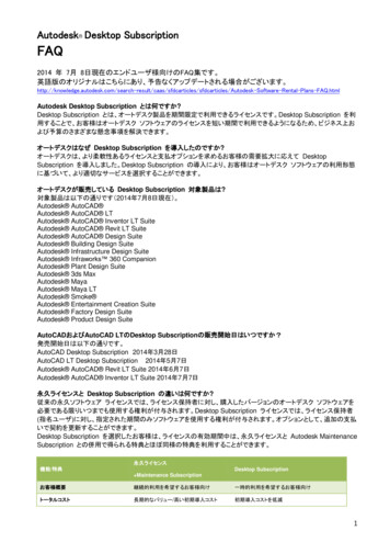
Shaft Component Generator for Autodesk Fusion 360 User GuideSections:The shaft is assembled from single sections (cylinder, cone and polygon) including features (chamfers,fillets, neck-downs, keyways and so on). In main window of plug-in choose type of shaft’s section. Makesplit (Split Selected Section) of section as well (available for cylindrical section only). According toselected section, the features are available.The selection displays the appropriate commands on the toolbar. The Settings command is alwaysavailable. For Cone, no middle features are available. For Polygon, no edge features are available, onlyThrough Hole is available. Insert Cylinder inserts the cylinder section after the selected shaft section. Split Selected Section splits the selected shaft cylinder while keeping the same length of theshaft. Insert Cone inserts cone section after the selected shaft section. Insert Polygon inserts polygon section after the selected shaft section. Collapse All Children collapses the section tree. Expand All Children expands the section tree. Settings opens the Settings dialog box where preferences for shaft 2D and 3D previews arespecified.Selected section and feature are displayed in the list where they can be edited or deleted.The graphical representation of features and sections are displayed in Autodesk Fusion 360 window as3D preview and in the Design tab as 2D preview (which is optional). Work with the preview as with 3DGrips. Double-click to display the Edit dialog box. Move the mouse cursor above the graphicalrepresentations to display a description of a section/feature.Copyright 2017 AMC Bridge7
Shaft Component Generator for Autodesk Fusion 360 User GuideAn example of what a user can expect is below.Copyright 2017 AMC Bridge8
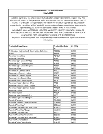
Shaft Component Generator for Autodesk Fusion 360 User GuideSection features:List of available features in the menu is filtered based on the section type (cone, cylinder, polygon).The sections and features are editable: Opens the appropriate dialog box to edit dimensions. Deletes the selected feature or section or bore.Click the arrow next to theicon to display the list of available section features.Click to add a feature.Following section features are available for cylindrical section: Through Hole Retaining Ring Groove Keyway groove Wrench Relief D (SI Units) Groove - A, Groove -BCopyright 2017 AMC Bridge9
Shaft Component Generator for Autodesk Fusion 360 User GuideFollowing section features are available for polygon section: Through HoleCopyright 2017 AMC Bridge10
Shaft Component Generator for Autodesk Fusion 360 User GuideThere are no available section features or cone section:An example of what user can expect is below.Copyright 2017 AMC Bridge11
Shaft Component Generator for Autodesk Fusion 360 User GuideDouble-click the feature inside of section tree to change Name, Size, Description, Position and Standard(available for keyways only) of feature.Copyright 2017 AMC Bridge12
Shaft Component Generator for Autodesk Fusion 360 User GuideCopyright 2017 AMC Bridge13
Shaft Component Generator for Autodesk Fusion 360 User GuideLeft/Right edge features:For edge features, a dialog box displays where the appropriate values are set. Click the middle featureicon to open the editing dialog box.The list of available features in the menu is filtered based on the section type (cone, cylinder, polygon)and based on the section position (first, in the middle, last).Click the arrow to display the list of available left/right edge features. Click to add a feature.Following left/right edge features are available for cylindrical section: Chamfer Fillet Thread Lock Nut Groove Plain Keyway Groove Keyway Groove with one rounded endCopyright 2017 AMC Bridge14
Shaft Component Generator for Autodesk Fusion 360 User GuideFollowing left/right edge features are available for cone section: Chamfer FilletFollowing left/right edge features are available for polygon section: ChamferCopyright 2017 AMC Bridge15
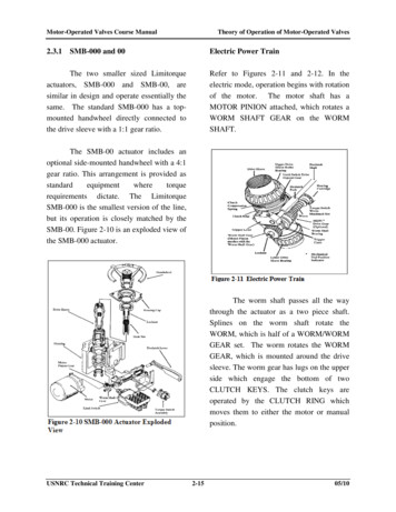
Shaft Component Generator for Autodesk Fusion 360 User GuideFollowing left/right edge features are available for cylindrical section which is located inside of shaft(between other sections): Chamfer Fillet Relief (SI, Din, Gost Units)Double-click on the feature inside of section tree to adjust parameters of the feature (example is forRelief-A, SI Units).Copyright 2017 AMC Bridge16
Shaft Component Generator for Autodesk Fusion 360 User GuideAn example of what user can expect is below.Copyright 2017 AMC Bridge17
Shaft Component Generator for Autodesk Fusion 360 User GuideBore on the Left: Insert Cylindrical Bore inserts inside section on the left after the selectedshaft section. Insert Conical Bore inserts inside cone section on the left after the selectedshaft section.Bore on the Right: Insert Cylindrical Bore inserts inside section on the left after the selected shaft section. Insert Conical Bore inserts inside cone section on the left after the selected shaft section.Copyright 2017 AMC Bridge18
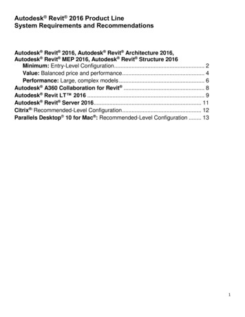
Shaft Component Generator for Autodesk Fusion 360 User GuideDouble-click the bore icon to adjust parameters of the bore.Click the arrow next to theicon to display the list of available section features.Click to add a feature.Following section features are available for bores: Retaining RingCopyright 2017 AMC Bridge19
Shaft Component Generator for Autodesk Fusion 360 User GuideAn example of what user can expect is below.Copyright 2017 AMC Bridge20
Shaft Component Generator for Autodesk Fusion 360 User GuideUninstallationUninstalling Shaft Component Generator can be performed in two ways:1) The installer should be relaunched by downloading it again from Autodesk App Store and choosingUninstall action.2) In Control Panel\Programs\Programs and Features (Windows 7/8/8.1/10), just as any otherapplication from the system.Add-in can be unloaded without uninstalling by clicking Stop button when the add-in is selected in thelist box on the Add-Ins tab of the Scripts and Add-Ins dialog.Unchecking Run on Startup causes the add-in not to be loaded in future sessions of Autodesk Fusion360.Copyright 2017 AMC Bridge21
Shaft Component Generator for Autodesk Fusion 360 User GuideAbout AMC BridgeAMC Bridge is a vendor of choice for software development services in the areas of computer aideddesign, engineering, manufacturing and construction. Since 1999 we have been delivering solutionsfor CAD, CAE, CAM, PDM, BIM and PLM applications. For over 15 years we have participated in thedevelopment of commercial software products and custom solutions for the engineering marketsbased on the variety of platforms from desktop and web to mobile and clouds.AMC Bridge helps to improve engineering process overhead by the development of 3D and 2Dmodeling software products, data, document and community management technologies, CAD datainteroperability, and many other aspects of software development for the engineering markets.Feel free to use wide experience of AMC Bridge team to find out all features and intricacies ofsoftware development process. Contact us any time and we will do our best to turn your ideas intoreality.303 Wyman Street, Suite 300 Waltham, MA 02451, USA 1 866-575-4791www.amcbridge.comFor all online inquiries, please contact: contact@amcbridge.comTechnical Support: support@amcbridge.comCopyright 2017 AMC Bridge22
Defines the placement of the shaft. Within the Autodesk Fusion 360 window, select cylindrical face or work axis, start plane and shaft orientation, as needed. While defining placement, the shaft is previewed in that location in the Autodesk Fusion 360 window. lick OK to create and constrain the shaft in the assembly.