Transcription
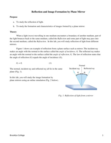
Reflection and Image Formation by Plane MirrorPurposea. To study the reflection of light.b. To study the formation and characteristics of images formed by a plane mirror.TheoryWhen a light (wave) travelling in one medium encounters a boundary of another medium, part ofthe light bounces back to the same medium, called the Reflection and some part of light may pass intothe second medium, called the Refraction. In this lab, you will study reflection of light from differentmirrors.Figure 1 shows an example of reflection from a plane surface such as mirror. The incident raymakes an angle with the normal to the surface called the angle of incidence, θi. The reflected ray makesan angle with the normal to the surface called the angle of reflection, θr. The law of reflection states thatthe angle of reflection (θr) equals the angle of incidence (θi),θr θi(1)The normal, incident ray and reflected ray all lie in the sameplane (Fig. 1).NormalReflected rayIncident rayIn this lab, you will study the image formation byplane mirrors using an online simulation (Fig. 2 below).Fig. 1: Reflection of light from a mirrorBrooklyn College1
Figure 2 illustrates how images are formed by a plane mirror. Consider a point ‘O’ on an object.The rays of light coming from the point reflect according to the laws of reflection. Out of severalpossible rays from the point, we need at least two rays to locate the image.normalOIFig. 2: Image formation by a plane mirror.For a plane mirror, as shown in Fig. 2, the normals are parallel for both incident rays, so they reflectwith different angles of reflection. The reflected rays upon incident on our eye see the image.Intersection of the reflected rays is the position of image. However, the reflected rays do not intersectas they are diverged. We have to back trace the reflected rays (by dotted lines) to find the intersection,I. Our eyes see as if the light is coming from the point I behind the mirror. Thus, it is a virtual image.Note the object distance (do) and image distance (di) is same in plane mirrors. But the distance of avirtual image is taken as a negative value. This is required by a sign convention for mirrors. For suchcase the magnification is 1 by the formula, m -di /do. That’s why you see your identical image on themirror. But why does your right hand become left hand and vice versa in mirror?Simulation toolsThis lab uses the online simulator:Plane mirrors: https://ophysics.com/l9.htmlProcedureThroughout, you must take screenshots of your work and include them in your final report, to showthat you have conducted the simulations.Plane mirror (The data sheet is on pages 4 and 5)(a) Reflection of light by a plane mirror1. Open the plane mirror simulation at https://ophysics.com/l9.html.2. The simulation opens with a default object which is a blue, vertical arrow. However, youcan alter the length and angle of the arrow. You can also observe light rays traveling fromyour choice of so-called “control points”.3. Check the box at the top of the simulation marked “Control points”. This will enable youto move the top and bottom of the object, and the 4 control points on the plane mirror.4. Check the box at the bottom of the simulation marked “Show Grid & Axes”. This willenable you to make measurements.Brooklyn College2
5. Move the control points for the object as follows:a. for the top of the object: (-6,2)b. for the bottom of the object: (-6,0).The object should now appear as a vertical arrow of height 2 units.6. Move the control points on the mirror to the following 4 positions: (0,-3), (0,-1), (0,1) and(0,3).7. Check the boxes marked “Show Incident Rays” and “Show Reflected Rays” and “ShowNormals”.8. Look at the angles made by the incident and reflected rays to the normal through eachcontrol point on the mirror. What can you say about the angle of incidence (relative to thenormal) and the angle of reflection (relative to the normal)?9. Uncheck all the boxes and click and drag the object to another position on the display of yourchoice. Feel free to rotate the object slightly, if you would like. Now, what would you predictwith respect to the relationship between the angle of incidence and angle of reflection from theobject in this new position? Check all the boxes again and inspect the angles. Was yourprediction correct?(b) Image of a point object formed by plane mirror1. You are now going to make a point object. Move the lower control point on the currentobject from the position (-6,0) to (-6,2), in other words so that both of the control points onthe object are at (-6,2). All rays should now start from that point.2. Click the box “Show Image” at the top of the screen and the box “Show Virtual Rays” at thebottom right of the screen. Where is the image located? Note its (x,y) coordinates. Is theimage virtual or real?3. Move the object so that it is a point object at each of the following locations: (-6,0) ; (-6,-2). [in each case, the top and bottom control points of the objectoverlap]In each case, note the (x,y) coordinates where the image is formed(c) Image of an extended object formed by a plane mirror1. Set the control points on the object to being different, in order to form an extendedobject (as in part a). Specifically, set the bottom control point on the object to (-5,0)and the top control point to (-7,2).2. What is the location of the image? Give the (x,y) coordinates of the top and bottom ofthe image. Is it real or virtual? Compute the object and image distances,andcorresponding to the bottom points of object and image and repeat also for the toppoints. Use these values in the computation part below.3. The whole object can be dragged by moving it using the mouse. Does the size of theimage change if the object is moved towards, or away from, the mirror? What does thistell you about our eyes’ perception of images in a flat mirror?Brooklyn College3
ComputationFor part (c), step 2 above, use the object distance and image distance corresponding to bottom points ofobject and image (and then again for top points). Are the points of image located at the same distancefrom the mirror as the corresponding points of object? For bottom points (and then for top points),calculate the ratio -di /do. What does it represent? (Hint: See the theory part).Questions1. What is meant by a “virtual image”?2. If you walk towards a full-length mirror, your image “walks” towards you. If your speed is1.5 m/s, what is the speed of your image?Data sheetName:Group:Date online- experiment performed:Part (a): Reflection of light by a plane mirrorStep 8) Angle of incidence relative to the normal:Angle of reflection relative to the normal:Step 9) New position of object:With the boxes unchecked, what relation do you see between angle of incidence and angle ofreflection?Check the boxes again, and compare to your prediction. Was your prediction correct?Part (b): Image of a point object formed by plane mirrorStep 2) Image location (x,y):Is the image virtual or real?Step 3) Object at (6,0): Image location (x,y):Object at (6, -2): Image location (x,y):Part (c) Image of an extended object formed by a plane mirrorStep 2) Location of Image: Top (x,y):Bottom (x,y):Is the image real or virtual?Step 3) Does the size of the image change if the object is moved towards the mirror?Does the size of the image change if the object is moved away from the mirror?What does this tell you about our eyes’ perception of images in a flat mirror?Computation: For part (c) step (2) measure the object distance, do and the image distance, difor bottom points (and repeat for top points). Are they equal for bottom (or top) points?Calculate the ratio -di /do (for bottom points):-di /do (for top points):What does this ratio represent?Answer to questions:1.2.Brooklyn College4
Use this page if you need additional spaceBrooklyn College5
For a plane mirror, as shown in Fig. 2, the normals are parallel for both incident rays, so they reflect with different angles of reflection. The reflected rays upon incident on our eye see the image. Intersection of the reflected rays is the position of image. However, the reflected rays do not intersect