Transcription
Operation ManualTemperature Controller ST49Revision 1.1, dated on 31.03.2008PSG Petro Service GmbH & Co. KG, Tel.: 49 (0) 6171 / 9750-0, FAX: -30, Email: info@psg-petroservice.de
Contents1.User Consideration.42.Product description and application.53.Controller architecture .54.Operation buttons and signal lamps .6Operation buttons .6Signal lamps .65.Configuration .7Menu level .7Adjustment of control parameters.7Parameter setting of the control setpoint.8Parameter tables and explanations .9Configuration forelectrical heated sample filter unit PFE, sample tube and sleeve .236.Status indications and error messages .237.Solid State Relay SSR (optional).248.Wiring diagram .269.Technical data .2710. Dimensions.2911. Software .30PSG Petro Service GmbH & Co. KG, Tel.: 49 (0) 6171 / 9750-0, FAX: -30, Email: info@psg-petroservice.dePage 3 of 32
1. User ConsiderationExplanation of used symbols:Particularly important informationWarning noticeNotice:This controller is designed only for industrial purposes.Read this operation manual carefully and completely. Start the installation and start-up afterwards.Only qualified personal who throughly understand the operation of this equipment should install andstart-up this equipment.Never work on any control equipment without first removing all power supplies from the equipment.Non-compliance with this warning may result in serious personal injury and/or equipment damage.Consider the max. switching load of the controller and the SSR (Solid-State-Relay) respectively (seetechnical data on page 27). Depending on the heating power the max. length of a controlled electricalheated tube bundle / sample line is limited.You shall not be entitled to duplicate this document or in respect of any content (wholly or partly) topass it on to third parties unless and to the extent expressly permitted.Although every effort has been taken to ensure the accuracy of this document, it may be necessarywithout notice to make amendments or correct omissions.PSG Petro Service GmbH & Co. KG (further “PSG”) cannot accept responsibility for damage, injury, orexpenses resulting from the preceding advices and warnings.PSG Petro Service GmbH & Co. KG, Tel.: 49 (0) 6171 / 9750-0, FAX: -30, Email: info@psg-petroservice.dePage 4 of 32
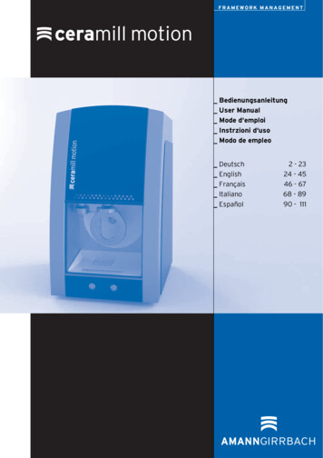
2. Product description and applicationThis micro-processed controller serves for temperature control of PSG electrical heated tube bundles /sample lines, sample filter units, sample tubes and sleeves. Beside resistance sensors andsemiconductor thermo element the multi-sensor input can equally process 0.10 V and/or 4.20 mA.The PID and/or thermostat controlling can be activated by parameter setting. There are differentoutputs available, such as two relay contacts, a voltage output for SSR and an analogue output. RedLED lamps indicate the status of the output relays. The setpoints and parameters determining theprocess are adjusted by a 4-field plastic foil keyboard.3. Controller architectureAll outputs can be allocated with a special controller function by different parameters (H41 H44).Each controller unit is configurated by the accordant parameters.Block diagram of the controller architecture /allocation of the outputs and control circuits (factory setting)PSG Petro Service GmbH & Co. KG, Tel.: 49 (0) 6171 / 9750-0, FAX: -30, Email: info@psg-petroservice.dePage 5 of 32
The controller is preset (factory setting) for PSG electrical heated tube bundles / sample lines (seeparameter table on page 9 et seqq.).In case of an upper / lower temperature alarm or a sensor failure (see parameter C9, C29, C49 andC87) the controller output K1 switches to the alarm state. Setting of a temperature limiter alarm outputK2 switches to the alarm state and the controlling is blocked as long as the correct keyword is entered(see menu levels / parameter P-- on page 7).All parameters, which has to be changed controlling an electrical heated sample filter unit, sampletube or a sleeve, is listed on page 23.4. Operation buttons and signal lampsOperation buttonsKey-UpPushing this key you can increase the parameter or parameter value or scroll theparameter list.Key-DownPushing this key you can decrease the parameter or parameter value or scroll theparameter list. In case of an alarm the buzzer function can be switched off with this key.Standby key (function key 1)Switching the controller on or off. After interruption of the power supply, parameter H17 isautomatically set.Key SETDisplaying setpoints and parameters. In combination with the Key-Up or Key-Down thevalues of setpoints and parameters are adjustable.Signal lampsLamp 1:Lamp 2:Lamp 3:Switch state output K1 (alarm relay, parameter H41)Switch state output K2 (limiter, parameter H42)Switch state output S3 (PID heating, voltage for SSR-device)PSG Petro Service GmbH & Co. KG, Tel.: 49 (0) 6171 / 9750-0, FAX: -30, Email: info@psg-petroservice.dePage 6 of 32
5. ConfigurationMenu levelPushing the UP and DOWN key simultanious for at least 4 seconds, the controllerchanges to the menu level. It consists of several submenus listed by the respective initial letterfollowed by 2 hyphen (e.g. C -- for the C-level).Also parameter P-- for unlocking the controller is part of this level.ParameterP-C-b-H-d-A--UntermenüController levelIntermediate levelHardware levelDefrost levelAnalogue levelFunktionEnter keyword -19 (negative value)Application parametersConnecting parametersHardware parametersDefrosting parameters (control circuit 1)Parameter for analogue in- and outputsAdjustment of control parametersThe selection of the submenu occurs by scrolling with the UP and DOWN key. Pushing the SET-keythe keyword of the selected level is requested. The keyword must be set by additionally pushing theUP or DOWN key (standard value: 0).The last parameter of the respective submenu (e.g. C99, b99.) corresponds to the current keyword ofthis level and can be changed there.PSG Petro Service GmbH & Co. KG, Tel.: 49 (0) 6171 / 9750-0, FAX: -30, Email: info@psg-petroservice.dePage 7 of 32
Loosing the keyword the controller has to be send to PSG for unlocking.Entering the correct keyword the controller enters to the submenu and the display shows the first listedparameter after releasing the SET key. Pushing the SET key, the value of the selected parameter isindicated. Additionally pushing the UP or DOWN key, the value can be set. Releasing all keys, thenew value is saved.If UP and DOWN keys are pushed simultaneous again for at least 4 seconds, the controller enters tothe submenu again. Upon repeated pushing for 4 seconds or no pushing of any key for more than 60seconds, the controller outputs the submenu back to the initial state.Parameter setting of the control setpointThe control setpoint C1 is accessible directly with the SET key. Pushing also the UP or DOWN key itcan be set.Parameter FunctionC1C2Control setpoint 1 for controlcircuit 1 and/or PID-regulationControl setpoint 2 for controlcircuit 1 (*)Adjustment rangeFactorysettingC10.C11180 CC10.C110,0 C* The activation of the second setpoint of circuit 1 C2 is indicated by a flashing LED on the right sideof the display. It can either be activated by the gate input or by the function key 1 (depending onparameter).PSG Petro Service GmbH & Co. KG, Tel.: 49 (0) 6171 / 9750-0, FAX: -30, Email: info@psg-petroservice.dePage 8 of 32
Parameter tables and explanationsC-level (Controller)This level contains the application parameters.Thermostat 1ParameterFunctionAdjustment range-99.999 CC2Setpoint control circuit 1Setpoint control circuit 1 (*)C3Offset for C1/C2C4Function of control circuit 1C5Hysteresis control circuit 1C1C6C7C8C9C10C11Hysteresis modecontrol circuit 1Minimum action time controlcircuit 1"ON"Minimum action time controlcircuit 1"OFF"Function control circuit 1at sensor failureControl range limitation,minimum Setpoint 1Control range limitation,maximum Setpoint 1Factorysetting180 C-99,0.99,0 K0,0 C-99,0.99,0 K0: heating function1: cooling function0,1.99,9 K0: symmetrical1: one-sided0,0 K0.400 sec.0 sec.0.400 sec.0 sec.0: relay off1: relay on011,0 K0-99,0 C.C11-99,0 CC10.999,0 C999,0 C* The activation of the second setpoint of circuit 1 C2 is indicated by a flashing LED on the right sideof the display. It can either be activated by the gate input or by the function key 1 (depending onparameter).Thermostat 2ParameterFunctionAdjustment rangeC21C22C23Setpoint control circuit 2 (b1 0)Limiter valueDelta W2 (b1 1)C24Function of control circuit 2C25Hysteresis control circuit 2Hysteresis modecontrol circuit 2Minimum action time controlcircuit 2 "ON"Minimum action time controlcircuit 2 "OFF""Function control circuit 2 atsensor failure-99.999 C-99.999 C-99.99 K0: heating function1: cooling function0,1.99,9 K0: symmetrical1: one-sidedC26C27C28C29Factorysetting0 C192 C8 K11 K00.400 sec.0 sec.0.400 sec.0 sec.0: relay off1: relay on0PSG Petro Service GmbH & Co. KG, Tel.: 49 (0) 6171 / 9750-0, FAX: -30, Email: info@psg-petroservice.dePage 9 of 32
Thermostat 3ParameterFunctionC43Setpoint control circuit 3(b2 0)Delta W3 (b2 1)C44Function of control circuit 3C45Hysteresis control circuit 3C41C46C47C48C49Hysteresis modecontrol circuit 3Minimum action time controlcircuit 3 "ON"Minimum action time controlcircuit 3 "OFF""Function control circuit 3at sensor failureAdjustment rangeFactorysetting-99.999 C0,0 C-99,0.99,0 K0: heating function1: cooling function0,1.99,9 K0: symmetrical1: one-sided0,0 K0.400 sec.0 sec.0.400 sec.0 sec.0: relay off1: relay on001,0 K0Alarm circuitParameterFunctionC61Lower alarm valueC62Upper alarm valueC63Alarm functionsC64Special function at limit alarmC65Hysteresis alarm circuitAdjustment range-99,0.C62-99,0: inactiveC61.999,00: Boundary alarm, relativeboundaries1: Boundary alarm, absolutebundaries2: Range alarm, relative boundaries3: Range alarm, absoluteboundaries4: Boundary alarm, relativeboundaries, alarm invers5: Boundary alarm, absoluteboundaries, alarm invers6: Range alarm, relativeboundaries, alarm invers7: Range alarm, absoluteboundaries, alarm invers0: not active1: flashing display2: buzzer3: buzzer flashing display4: like 3, buzzer can be cancelled5: like 4, restarts after 10 min.6: like 4, restarts after 30 min.0,1.99,9 KFactorysetting-20,08,0441 KPSG Petro Service GmbH & Co. KG, Tel.: 49 (0) 6171 / 9750-0, FAX: -30, Email: info@psg-petroservice.dePage 10 of 32
PID-controllerSetpoint of PID-controller is the setpoint of control circuit 1 (C1/C2)Parameter FunctionAdjustment rangeFactorysettingC85Proportional area at PIDregulationReset time at PID regulation(I-portion)Lead time at PID regulation(D-portion)Cycle time at PID regulationC86Control variable dead volume0,0.100,0 %0,0 %C87Function PID control circuit atsensor failure-100,0 %.0 100,0 %0,0 %PID-mode0: PID1: DiffPID (2 relays–heating, cooling)2: PID with dead band at analogueoutputC82C83C84C88C89C99Cycle time motor valve(Differential PID)Keyword C-level0,1 999,0 K25 K0.999 Sec., 0: inactive200 sec.0.999 Sec., 0: inactive50 sec.2.100 sec.15 sec.2.100 sec.-99 99908 sec.0Parameter explanations C-level:C1: Setpoint of control circuit 1 (thermostat)This value corresponds with the setpoint set at the first control level.C2: Setpoint of control circuit 1 (thermostat)The activation of the 2nd setpoint C2 is indicated by a blinking LED on the right side of the display. Theactivation occurs either by the gate input or by the function key 1. In case of an activated 2nd setpointby input E1 or function key 1 (depending on parameter), a recall of setpoint C2 is possible by pushingthe SET-key.C3: Offset of C1/C2This value will build the difference to the setpoint for control circuit 1, i.e. there is no regulationaccording to the preset value, but according to the sum of desired value and the value of C3.C4: Function of control circuit 1The function of the relays, i.e. heating or cooling, is programmable independently. Heating means adisconnection of the power supply, if the temperature (actual value) reaches the setpoint. Coolingmeans a connection to the power supply, if the temperature (actual value) is higher than the setpoint.PSG Petro Service GmbH & Co. KG, Tel.: 49 (0) 6171 / 9750-0, FAX: -30, Email: info@psg-petroservice.dePage 11 of 32
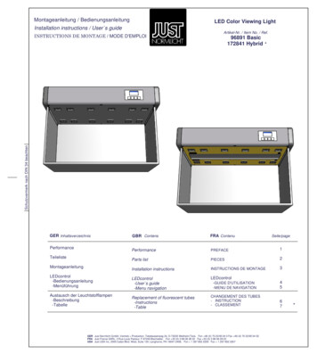
C5: Hysteresis of control circuit 1The hysteresis can be set symmetrically or one-sided at the desired value (see C6). At one-sidedsetting, the hysteresis works downward with heating contact and upward with cooling contact. Atsymmetrical hysteresis, half of the hysteresis value is effective below and half of the value above theswitching point (see diagram 1 and 2).Diagram 1: Heat controller,one-side hysteresisDiagram 2: Cool controller,symmetrical hysteresisC6: Hysteresis mode of control circuit 1This parameter set a symmetrically or one-sided hysteresis. At one-sided setting, the hysteresis worksdownward with heating contact and upward with cooling contact. At symmetrical hysteresis, half of thehysteresis value is effective below and half of the value above the switching point.C7/C8: Minimum action time of control circuit 1 "On"/"Off"These parameters permit a delay in switching on/off the relay in order to reduce the switchingfrequency. The adjusted time sets the entire minimum time period for a switching-on or switching- offphase.C9: Function of control circuit 1 at sensor failureIn case of a sensor failure the selected relay (see H41, 42, 43) switches back to preset state.C10/C11: Control range limitation of setpoint 1”minimum”/”maximum”The adjustment range of the setpoint can be limited in both directions. Using this limitation, anoperator of a system is not able to set unacceptable or dangerous setpoints.C21: Setpoint of control circuit 2 (thermostat) (b1 0)If parameter b1 1, this value is ineffective.C23: Value of deltaW2 (b1 1)In case of parameter b1 1, the setpoints for control circuit 1 and 2 are linked by a differential gapdeltaW2 (C23).The following applies: Setpoint thermostat 2 setpoint control circuit 1 (C1/C2) deltaW2.This difference can be a positive or negative value, i.e. a leading or lagging contact can be realised.C24: Function of control circuit 2The function of the relays, i.e. heating or cooling, is programmable independently. Heating means adisconnection of the power supply, if the temperature (actual value) reaches the setpoint. Coolingmeans a connection to the power supply, if the temperature (actual value) is higher than the setpoint.PSG Petro Service GmbH & Co. KG, Tel.: 49 (0) 6171 / 9750-0, FAX: -30, Email: info@psg-petroservice.dePage 12 of 32
C25: Hysteresis of control circuit 2The hysteresis can be set symmetrically or one-sided at the desired value (see C26). At one-sidedsetting, the hysteresis works downward with heating contact and upward with cooling contact. Atsymmetrical hysteresis, half of the hysteresis value is effective below and half of the value above theswitching point (see diagram 1 and 2).C26: Hysteresis mode of control circuit 2This parameter set a symmetrically or one-sided hysteresis. At one-sided setting, the hysteresis worksdownward with heating contact and upward with cooling contact. At symmetrical hysteresis, half of thehysteresis value is effective below and half of the value above the switching point.C27/C28: Minimum action time of control circuit 2 "On"/"Off"These parameters permit a delay in switching on/off the relay in order to reduce the switchingfrequency. The adjusted time sets the entire minimum time period for a switching-on or switching- offphase.C29: Function of control circuit 2 at sensor failureIn case of a sensor failure the selected relay (see H41, 42, 43) switches back to preset state.C41: Setpoint of thermostat 3 (b2 0)If parameter b2 1, this value is ineffective.C43: Value deltaW3 (b2 1)In case of parameter b2 1, the setpoints for control circuit 1 and 3 are linked by a differential gapdeltaW2 (C43).The following applies: Setpoint thermostat 3 setpoint control circuit 1 (C1/C2) deltaW3.This difference can be a positive or negative value, i.e. a leading or lagging contact can be realised.C44: Function of control circuit 3The function of the relays, i.e. heating or cooling, is programmable independently. Heating means adisconnection of the power supply, if the temperature (actual value) reaches the setpoint. Coolingmeans a connection to the power supply, if the temperature (actual value) is higher than the setpoint.C45: Hysteresis control of circuit 3The hysteresis can be set symmetrically or one-sided at the desired value (see C46). At one-sidedsetting, the hysteresis works downward with heating contact and upward with cooling contact. Atsymmetrical hysteresis, half of the hysteresis value is effective below and half of the value above theswitching point (see diagram 1 and 2).C46: Hysteresis mode of control circuit 3This parameter set a symmetrically or one-sided hysteresis. At one-sided setting, the hysteresis worksdownward with heating contact and upward with cooling contact. At symmetrical hysteresis, half of thehysteresis value is effective below and half of the value above the switching point.C47/C48: Minimum action time of control circuit 3 "On"/”Off”These parameters permit a delay in switching on/off the relay in order to reduce the switchingfrequency. The adjusted time sets the entire minimum time period for a switching-on or switching- offphase.C49: Function of control circuit 3 at sensor failureIn case of a sensor failure the selected relay (see H41, 42, 43) switches back to preset state.PSG Petro Service GmbH & Co. KG, Tel.: 49 (0) 6171 / 9750-0, FAX: -30, Email: info@psg-petroservice.dePage 13 of 32
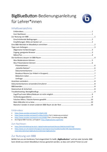
C61: Lower alarm valueC62: Upper alarm valueThe alarm output is a boundary alarm or a range alarm with one-sided hysteresis (see parameterC65). The limits of the boundary alarm as well as the range alarm can be relative, i.e. running with achanging setpoint C1/C2 or absolute, i.e. independent of the setpoint C1/C2. The hysteresis is onesided. In case of the boundary alarm inside the limits, in case of the range alarm outside the limits(see diagram 3-6).Presetting parameter C61 -99,0 the lower limit is not effective.Diagram 3: Boundary alarm, alarm contact normalC63 0 limits relativeC63 1 limits absoluteDiagram 4: Range alarm, alarm contact normalC63 2 limits relativeC63 3 limits relativeDiagram 5: Boundary alarm, alarm contact inverseC63 4 limits relativeC63 5 limits relativeDiagram 6: Range alarm, alarm contakt inverseC63 6 limits relativeC63 7 limits relativeC63: Function alarm outputThe alarm evaluates an upper and lower limit value (see parameters C61 and C62). Parameteractivates the alarm either if the temperature is inside the limits or outside the limits. In case of sensorfailure, the alarm will be activated independently of this adjustment. The output is also invertible, inorder to work as a disengaging (see diagram 3 – 6).C64: Special function at limit alarmIn case of an active alarm a blinking display and/or a buzzer is selectable by this parameter. A sensorfailure (display F1L or F1H) will be indicated by a blinking display and the buzzer independently of thepreset of this parameter.PSG Petro Service GmbH & Co. KG, Tel.: 49 (0) 6171 / 9750-0, FAX: -30, Email: info@psg-petroservice.dePage 14 of 32
C65: Hysteresis alarm circuitThe hysteresis is set one-sided to the preset limit value. It is effectively depending on alarm definitions(see diagram 3 - 6).C82: Proportional range of PID controllingWhen the actual value reaches the setpoint, the proportional term reduces the regulating variable /100 % to 0 %.C83: Integral time of PID controlling (integral term)C84: Deviation action time of PID controlling (differential term)A simple proportional controller can’t work without a deviation of the actual value and the setpoint. Theintegral term compensates this control deviation completely. The integral time is that time, thecompensation of a remaining temperature deviation about the value of the proportional term takes. Ashort integral time means a fast re-adjust. If the integral time is too short, the system is inclined tooscillate.The differential term is damping the temperature deviation. A long deviation action time means astrong damping effect. If the deviation time is too long, the system is inclined to oscillate.If zero (0) is preset, the parameters are not effective, so a PI or PD controlling can be realized.C85: Cycle time of PID controllingThe cycle time is that time, the control output completes one switch period, i.e. switching off and oneach one time. The shorter the cycle time the faster the controlling. But take note that a shorter cycletime results in a higher switch frequency of the output and will lead in a faster abrasion of the relay.For very fast closed loop controlled systems with high switch frequencies the voltage output isrecommended.C86: Regulating variable “dead band”With parameter C86 the value of the dead band ofthe PID regulating variable can be set in percent (%).Usually this takes place using a clocked PIDcontroller (relay) to realize a minimum turn-on time.Setting parameter C88 1 (differential PID) a pseudohysteresis can be realized. This will lead to areduction of the switch frequency, if the actual value setpoint. Setting parameter C88 2 the dead band willbe also available at analogue output (see sketch).C87: Function of PID control circuit in case of a sensor failureIn the case of a sensor failure, the PID regulating variable changes to the preset state.PSG Petro Service GmbH & Co. KG, Tel.: 49 (0) 6171 / 9750-0, FAX: -30, Email: info@psg-petroservice.dePage 15 of 32
C88: PID modeSwitching between PID standard (C88 0) and PID differential (C88 1).PID differential: The differential mode is particularly suitable for the use of control valves (e.g.K1 OPEN, K2 CLOSED). As long as the value calculated by the PID circuit remains constant, bothoutputs remain inactive, i.e. the valve stops at the current position.12345PID-Standard (C88 0)PIDK1: Heating K2: Cooling20 %20 %0%25 %25 %0%25 %25 %0%10 %10 %0%-20 %0%20 %PID-Differential (C88 1)DiffPID K1: Heating K2: Cooling 20 %20 %0% 5 %5%0% 00%0%-15 %0%15 %-30 %0%30 %Thus, control valves almost show the same controlling results as analogue valves. The table showsthe different behaviour of both modes within the same control system.C89: Cycle time control valve (DiffPID)This parameter sets the time the control valve needs to run from 0 % to 100 %.If parameter C88 1, the PID regulating variable is converted to this interval. The PID cycle time (C85)remains unaffected by this. When this time is defined, indication with rounded up values in secondsare recommended. Furthermore C85 should be C89. At 100 % the respective output remainsdurably active (synchronisation).C99: KeywordThis parameter is to set the keyword for the C-level.PSG Petro Service GmbH & Co. KG, Tel.: 49 (0) 6171 / 9750-0, FAX: -30, Email: info@psg-petroservice.dePage 16 of 32
b-level (between)This level contains the parameters for different combinations.Parameter FunctionAdjustment rangeb1Activation setpoint combination forb2Activation setpoint combination forthermostat 1 and 3 (deltaW3)b11b12b13Delay control circuit 1, 2, 3 after"Power-On"Mutual delay control circuit 1, 2, 3Alarm suppression after "Power-On","setpoint"b21Linkage analogue outputb99Keyword b-level0: no combination0: no combination1: setpoint thermostat 3 C1/C2 C43Factorysetting100.400 sec.0 sec.0.400 sec.0 sec.0.250 min.45 min.0: PID regulating variable1: actual value2: setpoint-99.99900Parameter explanations b-level:b1: Activation setpoint linking of thermostat 1 and thermostat 2 (deltaW2)This parameter determines whether the setpoints for thermostat 1 and 2 independently adjustable(parameter C21) or whether they are tied with one another by a switching offset deltaW2 (parameterC23).b2: Activation setpoint linking of thermostat 1 and thermostat 3 (deltaW3)This parameter determines whether the setpoints for thermostat 1 and 3 independently adjustable(parameter C41) or whether they are tied with one another by a switching offset deltaW2 (parameterC43).b11: Delay of control circuit 1, 2, 3 after "Power-On"This parameter allows a switching-on delay of relays after switching-on the power supply. This delaycorresponds with the time set here.b12: Mutual delay of control circuit 1, 2, 3This parameter makes a mutual switching-on delay of relays possible, depending on whichevercontact is switched first.b13: Alarm suppression after "Power-On", "setpoint"This parameter allows a switching-on delay of the alarm contact after switching on the power supply.This delay corresponds with the time set here.A change of this value will be effective after a reset (switching off and on the power supply).b21: Function of the analogue outputThis is to specify whether the analogue output carries the variable (PID), the actual value or thesetpoint. The allocation of the output voltage (max. 0.10 V) in correspondence with the indicatedvalue is effected by parameters A51 and A52. Output of voltages is always positive only.b99: KeywordThis parameter is to set the keyword for the b-level.PSG Petro Service GmbH & Co. KG, Tel.: 49 (0) 6171 / 9750-0, FAX: -30, Email: info@psg-petroservice.dePage 17 of 32
H-level (hardware)This level contains the hardware parameters.Parameter FunctionAdjustment rangeFactorysettingH1Key lockH11Indication mode display 1H12Display 1 modeH13Indication mode display 20: no key lock1: key lock0: integrals1: decimals in 0.5 K2: decimals in 0.1 K1: actual value2: setpoint3: PID variableN/AH14Display 2 modeN/A2H15Temperature scale0H16Indication standbyH17Mode following "Power-On" “H31Assigning function key 1H35Activation of keyacknowledgement0: Celsius 1: Fahrenheit0: display deactivated (point tothe right)1: AUS2: OFF0: Off1: On2: Auto0: no function1: standby key2: setpoint 1 / setpoint 23: upper temp. alarm value0: no key acknowledgement1: key acknowledgementwith buzzerH40Inversion of LED s3: not inverted3H41Function output K1H42H43H44Function output K2Function output S3Not usedH51Mains frequencyH99Keyword H-level0: no connection1: thermostat 12: thermostat 23: thermostat 34: alarm function5: PID-mode heating6: PID-mode cooling7: Limitersee H41see H410: 50 Hz1: 60 Hz-99 99902121130475000Parameter explanations H-level:H1: Key lockThe key lock allows a blocking of the control keys. In locked condition the adjustment of parameters bykeys is not possible. At the attempt to set the parameters despite key lock the message " " appearsin the display.PSG Petro Service GmbH & Co. KG, Tel.: 49 (0) 6171 / 9750-0, FAX: -30, Email: info@psg-petroservice.dePage 18 of 32
H11: Indication mode display 1The value can be indicated in integrals or with decimals in 0,5 K or 0,1 K. At indication in 0,5 K thevalue is rounded up or down. In general, all parameter indications are presented in 0,1 K.H12: Display 1 modeParameter H12 1 indicates the actual value, parameter H12 2 indicates the setpoint C1 or C2 andparameter H12 3 statically indicates the PID regulating variable in the display. Therefore, the currentactual value can only be indicated with parameter A01.H13: Indicator mode display 2Not evaluatedH14: Display 2 modeNot evaluatedH15: Temperature scaleIndication can be switched between Fahrenheit and Celsius. At conversion, the parameters andsetpoints maintain their numerical value and adjustment range. (Example: A controller with thesetpoint of 0 C is switched to Fahrenheit. The new setpoint is then interpreted as 0 F, whichcorresponds to a temperature of -18 C).Indication limits with F can be smaller than the actual measuring range!H16: Indication standbyIn standby mode the here set value appears in the display.H17: Mode following "Power-On"After switching on the mains voltage the controller automatically goes to the condition set here.Parameter H17 2 applies to the condition prior to the separation from the net.H31: Assigning function key 1Setting parameter H31 0 deactivates the key, parameter H31 1 functions as standby key. H31 2allows a change between setpoint 1 (C1) and setpoint 2 (C2) and with H31 3 the upper temperaturealarm value (par
PSG Petro Service GmbH & Co. KG, Tel.: 49 (0) 6171 / 9750-0, FAX: -30, Email: info@psg-petroservice.de Page 5 of 32 2. Product description and application . The PID and/or thermostat controlling can be activated by parameter setting. There are different outputs available, such as two relay contacts, a voltage output for SSR and an analogue .