Transcription
PEmicrowww.pemicro.comTechnical Summary forUSB Multilink Universal, Rev. D (PART# USB-ML-UNIVERSAL) andUSB Multilink Universal FX, Rev. C (PART# USB-ML-UNIVERSAL-FX)Document# PE4576, Version 1.161. Introduction2. Supported Devices3. Debug Headers4. Usage5. Driver Installation6. Connecting To The Target7. Troubleshooting - Startup Reset Sequence8. Firmware Updates/Architecture Selection9. Interface Libraries10.Third-Party IDEs & Other Compatible SoftwareUSB Multilink Universal & USB Multilink Universal FX11.Transition To Production Programming1IntroductionThe Multilink Universal and Multilink Universal FX are all-in one debug interfaces which accelerate the debug and flashprogramming process, saving valuable development time. Both Multilinks provide access to debug modes on a wide range ofNXP & other ARM Cortex microcontroller families by communicating between the target device and a laptop/PC via the target’sstandard debug header and the laptop/PC’s USB port.FX Note: In addition, the USB Multilink Universal FX offers up to 10X faster download speeds, can provide targetpower, and supports some additional, older NXP architectures. The greatest speed boosts occur when working withsynchronous devices.2Supported DevicesBoth the Multilink Universal and Multilink Universal FX support the following 8-/16-/32-bit NXP device families:· Kinetis · LPC· i.MX· S32 (ARM)· Automotive· Sensors· Vybrid· MPC55xx-57xx· ColdFire V1/ColdFire V1· S32 (Power)· ColdFire V2-4· HCS08· RS08· HC(S)12(X)· S12Z· DSC· MPC5xx/8xx (FX only)· HC16/683xx (FX only)Both models also support STMicroelectronics’ SPC5 devices.ARM Cortex-M DevicesIn addition, the Multilink Universal and Multilink Universal FX support ARM Cortex-M devices from these manufacturers:· NXP (see above)· Cypress Semiconductor· Infineon· Maxim Integrated· Microchp (Atmel)· Nordic Semiconductor· OnBright· Redpine Signals· Silergy Teridian· Silicon Labs· STMicroelectronics· Texas Instruments· Toshiba· WIZnet 2012-2019 P&E Microcomputer Systems, Inc. Kinetis, and ColdFire are registered trademarks of NXP Semiconductor. ARM and Cortex are registeredtrademarks of ARM Limited. The Power Architecture wordmark and related marks are trademarks and service marks licensed by Power.org.
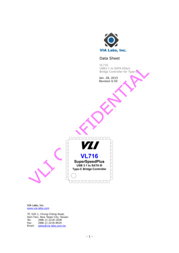
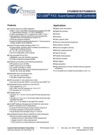
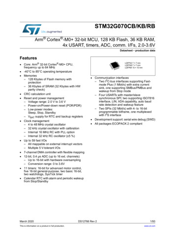
For a complete listing of supported ARM Cortex-M devices or to request support for a device, visit PEmicro at:http://www.pemicro.com/arm3Debug HeadersEach of the supported families of NXP & other ARM Cortex microcontrollers are represented by headers located inside the unit.The headers for Ports A-D & Port H (FX only) are dual-row with a .100” pitch, and the headers for Ports F-G are dual-row witha .050” pitch. The pin-outs for these connections and the families that they support are shown below. Port E, the 16-pin JTAG/COP connector, is not currently supported.Universal/Universal FX Pin-Outs, Ports A-DUniversal/Universal FX Pin-Outs, Ports F-HThe user can take advantage of debug modes to halt normal processor execution and use a computer to control the processor.The user can then directly control the target's execution, read/write registers and memory values, debug code on the processor,and program internal or external FLASH memory devices.FX Note: The USB Multilink Universal FX is capable of providing power (5V or 3.3V) directly to the target processor viathe TVCC pin. This removes the need for an external power supply for systems requiring 200mA of current or less. TheTVCC pin should be connected even in cases when the target is self-powered.4UsageThe user connects a ribbon cable between the target's debug header and one of the multiple ports on the Multilink. The layoutof the ports and which device type each supports is shown in the figure below. Do not attempt to use multiple ports at once, asthis may damage both the target processors as well as the Multilink.USB Multilink Universal & USB Multilink Universal FX - Technical Summary
Universal/Universal FX Header Layout (Pin 1 Highlighted)The USB Multilink Universal and Universal FX interfaces will work with targets whose processor power supply is in the range of1.8V to 5V. Both Multilink models have a female type B USB connector. Use a Type A to Type B male-to-male USB cable toconnect the interface to the PC.There are two LEDs on the Multilink interface. The blue LED indicates that the interface is powered and running. The yellowLED indicates that target power has been detected.Note:Pin 24 of the 26-pin ColdFire ribbon cable is intentionally disconnected to reduce noise. If connecting to a ColdFire V24 processor which requires synchronous communication, such as the MCF5272 and MCF5206(E), a CABLE-CFADAPTER (sold separately) is required.Note:To avoid improper connections, the red stripe of the ribbon cable should always be oriented towards Pin 1, both on theMultilink port and the target processor header. In the Header Layout figure above, Pin 1 for each header is indicated bya white square .The USB Multilink Universal and Universal FX are USB devices. If a USB Hub is used, it must be a self-powered hub (i.e. withits own power supply). By default, the USB protocol used is USB 2.0.Providing Power To TargetWhen using the the Multilink Universal FX, if the user wishes to provide power to the target the JP10 Jumper (FX only) is usedto enable this option and select the voltage. A shunt at position 1-2 enables 5V, while a shunt at position 2-3 enables 3.3V.5Driver InstallationBefore connecting the Multilink to the PC, the appropriate drivers need to be installed on the PC. The Multilink drivers aresupported on Windows XP, 2000, 2003, Vista, 7, 8, and 10. These drivers are automatically installed when installing NXP’sCodeWarrior or any of PEmicro’s recent software development packages. If you have installed a recent version of these thenthe instructions for manual installation that follow are not necessary. However, Windows 7 users who are installing softwaredistributed before December 28, 2009 will need to obtain the latest version of the drivers and install them manually. A copy ofthe driver installation program may be downloaded from the “Downloads” section of PEmicro’s “Support Center” located at http://www.pemicro.com. If you are using third-party software, make sure you have a version which supports your specific interface(Universal/FX). Once you have obtained the latest version of the driver installation program, please use the instructions belowto manually install the drivers.When the cable is plugged in, the operating system should indicate that it has found a driver for the attached interface. Followthe instructions in the “Found New Hardware Wizard” dialog for having Windows automatically install the driver.If you connected the Multilink interface prior to installing the drivers, Windows will not have been able to find the appropriatedriver and may have disabled the device. If you unplug the device and then plug it in again, Windows will automatically disableit even if you have installed the drivers. To force Windows to attempt to load the driver again, perform the following steps whilethe Multilink interface is plugged into the computer:1. Open the Control Panel: Start Button [ - Settings ] - Control Panel. (You will not need to select “Settings” on Vista andWindows 7).2. Double Click the “System” Icon. (Windows 7: “System and Security”)3. Select the “Hardware” Tab. (Windows 7: “Hardware and Sound”, Windows Vista: skip this step)4. Click the “Device Manager” Button. (Windows 7: “Devices and Printers - Device Manager”)USB Multilink Universal & USB Multilink Universal FX - Technical Summary
5. The “USB Multilink 2.0” device will be shown with an exclamation point next to it. Double-click this device.6. Click the “Reinstall Driver ” button and follow the dialog instructions to have Windows automatically install the driver.(Windows 7: First click the “Driver” tab, then select “Update Driver.”)7. If the hardware still has a yellow exclamation mark next to it, right click on it and select uninstall. The USB Multilink shoulddisappear from the list. Unplug the USB Multilink and then plug it into the PC again. A new Hardware Found dialog will popup; follow the dialog instructions and have Windows automatically install the driver.6Connecting To The TargetThe following is the proper connection sequence to connect the PC to the target system via the Multilink interface:1. Make sure the target power is OFF and the USB Multilink Universal or Universal FX is not connected to either the target orthe PC2. Open the Multilink and connect a ribbon cable from the correct Multilink port to the target. Make sure that the ribbon cableis plugged into the target with the proper orientation. PIN 1 is indicated by a 1 next to the port.3. Connect the Multilink to the PC via a USB cable. The Blue LED on the Multilink should illuminate.4. Turn the target power on. The Yellow LED on the Multilink should illuminate.Before disconnecting the setup, turn the target power off.7Troubleshooting - Startup Reset SequenceNote that if the Multilink does not enter debug mode, the program issues the error message “Cannot enter background mode.” Ifyou receive this message you should check your hardware with a scope, logic analyzer or logic probe. First check for power on,then check to make sure the processor oscillator is running. Finally, look for the startup sequence for your microprocessor thatis listed below.Port A – JTAG/ONCE – MPC55xx-57xx & STMicroelectronics SPC5, DSC, S32 (Power)a. RESET (Pin-9) is driven low (to processor).b. Activity appears on TCK (Pin-5), TDI (Pin-1) and TDO (Pin-3). (PC software instructs the processor to enable debugmode).c. RESET (Pin-9) is released by the interface and will go high.d. Activity appears on TCK (Pin-5), TDI (Pin-1) and TDO (Pin-3). (Debug activity).Ports B, F, G – ARM JTAG - Kinetis, LPC, S32 (ARM) & other ARM Cortex devicesa. RESET is driven low (to processor).b. Activity appears on TCK, TDI and TDO (PC software instructs the processor to enable debug mode).c. RESET is released by the interface and will go high.d. Activity appears on TCK , TDI and TDO (Debug activity).Ports B, F, G – ARM SWD - Kinetis, LPC, S32 (ARM) & other ARM Cortex devicesa. RESET is driven low (to processor).b. Activity appears on SWD CLK and SWD DIO (PC software instructs the processor to enable debug mode).c. RESET is released by the interface and will go high.d. Activity appears on SWD CLK and SWD DIO (Debug activity).Port C – BDMRS08, HCS08, S12Z, ColdFire V1a. Debug activity is seen on BKGD (Pin-1).HC(S)12(X)a. BKGD (Pin-1) and RESET (Pin-4) are pulled low by the interface.b. After 5 milliseconds, RESET (Pin-4) is released and goes high.c. After 10 milliseconds, BKGD (Pin-1) is released and goes high.d. After 20 more milliseconds, debug activity is seen on BKGD (Pin-1).Port D – Coldfire V2/V3/V4a. BKPT (Pin-2), DSI (Pin-8), and DSCLK (Pin-4) signals are driven low.b. RESET (Pin-7) is driven low for 20 milliseconds and released.c. After RESET is released and if the processor has correctly entered background mode, the PST0 (Pin-15), PST1 (Pin14), PST2 (Pin-13) and PST3 (Pin-12) lines should all be driven high by the processor.d. Activity (changing signals) is seen on the DSI, DSO, and DSCLK signals. The activity on the DSCLK and DSI lines isgenerated by the PC and the activity on the DSO line is generated by the processor.Port E – JTAG/COP (Not yet supported)Port HUSB Multilink Universal & USB Multilink Universal FX - Technical Summary
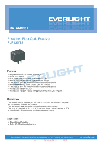
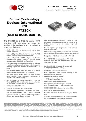
HC16/683XX (FX Only)a. BKPT/DSCLK is pulled low (to processor).b. Delay 1ms.c. RESET is pulled low (to processor).d. Delay 20ms.e. RESET is released (tri state, should be pulled up on target).f. Wait for FREEZE (out of processor).g. Shifting activity appears on DSCLK, DSI and DSO.MPC5xx/8xx (FX Only)a. DSCK is driven high and DSI is driven low (to processor).b. Delay 1ms.c. HRESET or SRESET is driven low (usually this will be HReset).d. Delay 20ms.e. HRESET is released (tri-state, should be pulled up on target).f. Shifting activity appears on DSCLK, DSI and DSO. (PC software communicating with target to determine if debug modewas successfully entered).8Firmware Updates/Architecture SelectionThe Multilink Universal and Universal FX use firmware updates to change between modes of operation to support differentfamilies of microcontrollers. Older versions of PEmicro's software and third-party software are not able to automaticallyconfigure these Multilinks when the target is switched to a different family of microcontrollers. If you are not using the latestversion of PEmicro software, please contact us to determine if you are eligible for a discounted upgrade to the latest version ofyour software. You may also download a manual configuration utility for the Multilink from the Support Center or correspondingproduct page on our website:http://www.pemicro.com/support/downloads find.cfm9Interface LibrariesPEmicro produces a set of interface libraries which allow the user to directly control the USB Multilink Universal or Universal FXfrom any Windows Development environment which can interact with a DLL. The interface libraries come with examples forcontrolling the Multilink interface from Microsoft Visual C as well as Borland Delphi. More details can be found on the InterfaceLibraries page on the PEmicro website:http://www.pemicro.com/products/product processor.cfm?category 910Third Party IDEs & Other Compatible SoftwareThe USB Multilink Universal and Universal FX are supported by recent versions of NXP’s MCUXpresso, CodeWarrior, KinetisDesign Studio, and S32 Design Studio, as well as third-party toolchains such as those from IAR, Keil, Silicon Labs. Cosmic, andMentor Graphics. A list of third party ARM IDEs can be found ultilinks also work with PEmicro software, including our no-cost, fully-featured GDB Server Plug-in for Eclipse-based ARMIDEs.It is recommended that you check with the vendor regarding support for your specific part. Information on compatible PEmicrosoftware can be found in the “Products” section of PEmicro’s website: pemicro.com.11Transition To Production ProgrammingThe USB Multilink Universal and Universal FX are intended fordevelopment and are not designed to accommodate the demands ofproduction programming. However, PEmicro’s Cyclone LC and CycloneFX programmers are specifically engineered to withstand the rigors of aproduction environment and will provide a seamless transition from theMultilink. In addition. the Cyclone FX offers an expanded feature setwhich includes faster communications, larger storage, expandablestorage, enhanced security including SAP image encryption andprogramming restrictions, and expansion ports. More information isavailable online at: pemicro.com/cyclone.Cyclone LC programmerUSB Multilink Universal & USB Multilink Universal FX - Technical Summary
USB Multilink Universal, Rev. D (PART# USB-ML-UNIVERSAL) and USB Multilink Universal FX, Rev. C (PART# USB-ML-UNIVERSAL-FX) Document# PE4576, Version 1.16 1. Introduction 2. Supported Devices 3. Debug Headers 4. Usage 5. Driver Installation 6. Connecting To The Target 7. Troubleshooting - Startup Reset Sequence 8. Firmware Updates/Architecture .