Transcription
STM32G070CB/KB/RBArm Cortex -M0 32-bit MCU, 128 KB Flash, 36 KB RAM,4x USART, timers, ADC, comm. I/Fs, 2.0-3.6VDatasheet - production dataFeatures Core: Arm 32-bit Cortex -M0 CPU,frequency up to 64 MHz -40 C to 85 C operating temperature Memories– 128 Kbytes of Flash memory withprotection– 36 Kbytes of SRAM (32 Kbytes with HWparity check) CRC calculation unit Reset and power management– Voltage range: 2.0 V to 3.6 V– Power-on/Power-down reset (POR/PDR)– Low-power modes: Sleep, Stop, Standby– VBAT supply for RTC and backup registers Clock management– 4 to 48 MHz crystal oscillator– 32 kHz crystal oscillator with calibration– Internal 16 MHz RC with PLL option– Internal 32 kHz RC oscillator ( 5 %)LQFP32 7 7 mmLQFP48 7 7 mmLQFP64 10 10 mm Communication interfaces– Two I2C-bus interfaces supporting Fastmode Plus (1 Mbit/s) with extra currentsink, one supporting SMBus/PMBus andwakeup from Stop mode– Four USARTs with master/slavesynchronous SPI; two supporting ISO7816interface, LIN, IrDA capability, auto baudrate detection and wakeup feature– Two SPIs (32 Mbit/s) with 4- to 16-bitprogrammable bitframe, one multiplexedwith I2S interface Development support: serial wire debug (SWD) All packages ECOPACK 2 compliant Up to 59 fast I/Os– All mappable on external interrupt vectors– Multiple 5 V-tolerant I/Os 7-channel DMA controller with flexible mapping 12-bit, 0.4 µs ADC (up to 16 ext. channels)– Up to 16-bit with hardware oversampling– Conversion range: 0 to 3.6V 11 timers: 16-bit for advanced motor control,five 16-bit general-purpose, two basic 16-bit,two watchdogs, SysTick timer Calendar RTC with alarm and periodic wakeupfrom Stop/StandbyMarch 2020This is information on a product in full production.DS12766 Rev 21/93www.st.com
ContentsSTM32G070CB/KB/RBContents1Introduction . . . . . . . . . . . . . . . . . . . . . . . . . . . . . . . . . . . . . . . . . . . . . . . . 82Description . . . . . . . . . . . . . . . . . . . . . . . . . . . . . . . . . . . . . . . . . . . . . . . . . 93Functional overview . . . . . . . . . . . . . . . . . . . . . . . . . . . . . . . . . . . . . . . . 123.1Arm Cortex -M0 core with MPU . . . . . . . . . . . . . . . . . . . . . . . . . . . . . 123.2Memory protection unit . . . . . . . . . . . . . . . . . . . . . . . . . . . . . . . . . . . . . . . 123.3Embedded Flash memory . . . . . . . . . . . . . . . . . . . . . . . . . . . . . . . . . . . . 123.4Embedded SRAM . . . . . . . . . . . . . . . . . . . . . . . . . . . . . . . . . . . . . . . . . . . 133.5Boot modes . . . . . . . . . . . . . . . . . . . . . . . . . . . . . . . . . . . . . . . . . . . . . . . 143.6Cyclic redundancy check calculation unit (CRC) . . . . . . . . . . . . . . . . . . . 143.7Power supply management . . . . . . . . . . . . . . . . . . . . . . . . . . . . . . . . . . . 14Power supply schemes . . . . . . . . . . . . . . . . . . . . . . . . . . . . . . . . . . . . . 143.7.2Power supply supervisor . . . . . . . . . . . . . . . . . . . . . . . . . . . . . . . . . . . . 153.7.3Voltage regulator . . . . . . . . . . . . . . . . . . . . . . . . . . . . . . . . . . . . . . . . . . 153.7.4Low-power modes . . . . . . . . . . . . . . . . . . . . . . . . . . . . . . . . . . . . . . . . . 163.7.5Reset mode . . . . . . . . . . . . . . . . . . . . . . . . . . . . . . . . . . . . . . . . . . . . . . 163.7.6VBAT operation . . . . . . . . . . . . . . . . . . . . . . . . . . . . . . . . . . . . . . . . . . . 173.8Interconnect of peripherals . . . . . . . . . . . . . . . . . . . . . . . . . . . . . . . . . . . . 173.9Clocks and startup . . . . . . . . . . . . . . . . . . . . . . . . . . . . . . . . . . . . . . . . . . 183.10General-purpose inputs/outputs (GPIOs) . . . . . . . . . . . . . . . . . . . . . . . . . 193.11Direct memory access controller (DMA) . . . . . . . . . . . . . . . . . . . . . . . . . . 193.12DMA request multiplexer (DMAMUX) . . . . . . . . . . . . . . . . . . . . . . . . . . . . 203.13Interrupts and events . . . . . . . . . . . . . . . . . . . . . . . . . . . . . . . . . . . . . . . . 203.143.152/933.7.13.13.1Nested vectored interrupt controller (NVIC) . . . . . . . . . . . . . . . . . . . . . . 203.13.2Extended interrupt/event controller (EXTI) . . . . . . . . . . . . . . . . . . . . . . 21Analog-to-digital converter (ADC) . . . . . . . . . . . . . . . . . . . . . . . . . . . . . . 213.14.1Temperature sensor . . . . . . . . . . . . . . . . . . . . . . . . . . . . . . . . . . . . . . . . 223.14.2Internal voltage reference (VREFINT) . . . . . . . . . . . . . . . . . . . . . . . . . . . 223.14.3VBAT battery voltage monitoring . . . . . . . . . . . . . . . . . . . . . . . . . . . . . . . 22Timers and watchdogs . . . . . . . . . . . . . . . . . . . . . . . . . . . . . . . . . . . . . . . 223.15.1Advanced-control timer (TIM1) . . . . . . . . . . . . . . . . . . . . . . . . . . . . . . . 233.15.2General-purpose timers (TIM3, 14, 15, 16, 17) . . . . . . . . . . . . . . . . . . . 23DS12766 Rev 2
STM32G070CB/KB/RBContents3.15.3Basic timers (TIM6 and TIM7) . . . . . . . . . . . . . . . . . . . . . . . . . . . . . . . . 243.15.4Independent watchdog (IWDG) . . . . . . . . . . . . . . . . . . . . . . . . . . . . . . . 243.15.5System window watchdog (WWDG) . . . . . . . . . . . . . . . . . . . . . . . . . . . 243.15.6SysTick timer . . . . . . . . . . . . . . . . . . . . . . . . . . . . . . . . . . . . . . . . . . . . . 243.16Real-time clock (RTC), tamper (TAMP) and backup registers . . . . . . . . . 253.17Inter-integrated circuit interface (I2C) . . . . . . . . . . . . . . . . . . . . . . . . . . . . 253.18Universal synchronous/asynchronous receiver transmitter (USART) . . . 263.19Serial peripheral interface (SPI) . . . . . . . . . . . . . . . . . . . . . . . . . . . . . . . . 273.20Development support . . . . . . . . . . . . . . . . . . . . . . . . . . . . . . . . . . . . . . . . 283.20.1Serial wire debug port (SW-DP) . . . . . . . . . . . . . . . . . . . . . . . . . . . . . . . 284Pinouts, pin description and alternate functions . . . . . . . . . . . . . . . . . 295Electrical characteristics . . . . . . . . . . . . . . . . . . . . . . . . . . . . . . . . . . . . 405.1Parameter conditions . . . . . . . . . . . . . . . . . . . . . . . . . . . . . . . . . . . . . . . . 405.1.1Minimum and maximum values . . . . . . . . . . . . . . . . . . . . . . . . . . . . . . . 405.1.2Typical values . . . . . . . . . . . . . . . . . . . . . . . . . . . . . . . . . . . . . . . . . . . . 405.1.3Typical curves . . . . . . . . . . . . . . . . . . . . . . . . . . . . . . . . . . . . . . . . . . . . 405.1.4Loading capacitor . . . . . . . . . . . . . . . . . . . . . . . . . . . . . . . . . . . . . . . . . 405.1.5Pin input voltage . . . . . . . . . . . . . . . . . . . . . . . . . . . . . . . . . . . . . . . . . . 405.1.6Power supply scheme . . . . . . . . . . . . . . . . . . . . . . . . . . . . . . . . . . . . . . 415.1.7Current consumption measurement . . . . . . . . . . . . . . . . . . . . . . . . . . . 415.2Absolute maximum ratings . . . . . . . . . . . . . . . . . . . . . . . . . . . . . . . . . . . . 425.3Operating conditions . . . . . . . . . . . . . . . . . . . . . . . . . . . . . . . . . . . . . . . . 435.3.1General operating conditions . . . . . . . . . . . . . . . . . . . . . . . . . . . . . . . . . 435.3.2Operating conditions at power-up / power-down . . . . . . . . . . . . . . . . . . 435.3.3Embedded reset and power control block characteristics . . . . . . . . . . . 435.3.4Embedded voltage reference . . . . . . . . . . . . . . . . . . . . . . . . . . . . . . . . . 445.3.5Supply current characteristics . . . . . . . . . . . . . . . . . . . . . . . . . . . . . . . . 455.3.6Wakeup time from low-power modes and voltage scaling transition times . . . . . . . . . . . . . . . . . . . . . . . . . . . . . . . . . . . . . . . . . . . . 505.3.7External clock source characteristics . . . . . . . . . . . . . . . . . . . . . . . . . . . 525.3.8Internal clock source characteristics . . . . . . . . . . . . . . . . . . . . . . . . . . . 565.3.9PLL characteristics . . . . . . . . . . . . . . . . . . . . . . . . . . . . . . . . . . . . . . . . . 575.3.10Flash memory characteristics . . . . . . . . . . . . . . . . . . . . . . . . . . . . . . . . 585.3.11EMC characteristics . . . . . . . . . . . . . . . . . . . . . . . . . . . . . . . . . . . . . . . . 595.3.12Electrical sensitivity characteristics . . . . . . . . . . . . . . . . . . . . . . . . . . . . 60DS12766 Rev 23/934
Contents6STM32G070CB/KB/RB5.3.13I/O current injection characteristics . . . . . . . . . . . . . . . . . . . . . . . . . . . . 615.3.14I/O port characteristics . . . . . . . . . . . . . . . . . . . . . . . . . . . . . . . . . . . . . . 625.3.15NRST input characteristics . . . . . . . . . . . . . . . . . . . . . . . . . . . . . . . . . . 665.3.16Analog switch booster . . . . . . . . . . . . . . . . . . . . . . . . . . . . . . . . . . . . . . 675.3.17Analog-to-digital converter characteristics . . . . . . . . . . . . . . . . . . . . . . . 675.3.18Temperature sensor characteristics . . . . . . . . . . . . . . . . . . . . . . . . . . . . 725.3.19VBAT monitoring characteristics . . . . . . . . . . . . . . . . . . . . . . . . . . . . . . . 725.3.20Timer characteristics . . . . . . . . . . . . . . . . . . . . . . . . . . . . . . . . . . . . . . . 725.3.21Characteristics of communication interfaces . . . . . . . . . . . . . . . . . . . . . 73Package information . . . . . . . . . . . . . . . . . . . . . . . . . . . . . . . . . . . . . . . . 816.1LQFP64 package information . . . . . . . . . . . . . . . . . . . . . . . . . . . . . . . . . . 816.2LQFP48 package information . . . . . . . . . . . . . . . . . . . . . . . . . . . . . . . . . . 846.3LQFP32 package information . . . . . . . . . . . . . . . . . . . . . . . . . . . . . . . . . . 876.4Thermal characteristics . . . . . . . . . . . . . . . . . . . . . . . . . . . . . . . . . . . . . . 906.4.1Reference document . . . . . . . . . . . . . . . . . . . . . . . . . . . . . . . . . . . . . . . 907Ordering information . . . . . . . . . . . . . . . . . . . . . . . . . . . . . . . . . . . . . . . 918Revision history . . . . . . . . . . . . . . . . . . . . . . . . . . . . . . . . . . . . . . . . . . . 924/93DS12766 Rev 2
STM32G070CB/KB/RBList of tablesList of tablesTable 1.Table 2.Table 3.Table 4.Table 5.Table 6.Table 7.Table 8.Table 9.Table 10.Table 11.Table 12.Table 13.Table 14.Table 15.Table 16.Table 17.Table 18.Table 19.Table 20.Table 21.Table 22.Table 23.Table 24.Table 25.Table 26.Table 27.Table 28.Table 29.Table 30.Table 31.Table 32.Table 33.Table 34.Table 35.Table 36.Table 37.Table 38.Table 39.Table 40.Table 41.Table 42.Table 43.Table 44.Table 45.Table 46.Table 47.STM32G070CB/KB/RB family device features and peripheral counts . . . . . . . . . . . . . . . . 10Access status versus readout protection level and execution modes. . . . . . . . . . . . . . . . . 13Interconnect of STM32G070CB/KB/RB peripherals . . . . . . . . . . . . . . . . . . . . . . . . . . . . . . 17Temperature sensor calibration values. . . . . . . . . . . . . . . . . . . . . . . . . . . . . . . . . . . . . . . . 22Internal voltage reference calibration values . . . . . . . . . . . . . . . . . . . . . . . . . . . . . . . . . . . 22Timer feature comparison . . . . . . . . . . . . . . . . . . . . . . . . . . . . . . . . . . . . . . . . . . . . . . . . . . 23I2C implementation . . . . . . . . . . . . . . . . . . . . . . . . . . . . . . . . . . . . . . . . . . . . . . . . . . . . . . . 26USART implementation . . . . . . . . . . . . . . . . . . . . . . . . . . . . . . . . . . . . . . . . . . . . . . . . . . . 27SPI/I2S implementation . . . . . . . . . . . . . . . . . . . . . . . . . . . . . . . . . . . . . . . . . . . . . . . . . . . 28Terms and symbols used in Table 11 . . . . . . . . . . . . . . . . . . . . . . . . . . . . . . . . . . . . . . . . . 30Pin assignment and description . . . . . . . . . . . . . . . . . . . . . . . . . . . . . . . . . . . . . . . . . . . . . 31Port A alternate function mapping . . . . . . . . . . . . . . . . . . . . . . . . . . . . . . . . . . . . . . . . . . . 36Port B alternate function mapping . . . . . . . . . . . . . . . . . . . . . . . . . . . . . . . . . . . . . . . . . . . 37Port C alternate function mapping . . . . . . . . . . . . . . . . . . . . . . . . . . . . . . . . . . . . . . . . . . . 38Port D alternate function mapping . . . . . . . . . . . . . . . . . . . . . . . . . . . . . . . . . . . . . . . . . . . 39Port F alternate function mapping. . . . . . . . . . . . . . . . . . . . . . . . . . . . . . . . . . . . . . . . . . . . 39Voltage characteristics . . . . . . . . . . . . . . . . . . . . . . . . . . . . . . . . . . . . . . . . . . . . . . . . . . . . 42Current characteristics . . . . . . . . . . . . . . . . . . . . . . . . . . . . . . . . . . . . . . . . . . . . . . . . . . . . 42Thermal characteristics. . . . . . . . . . . . . . . . . . . . . . . . . . . . . . . . . . . . . . . . . . . . . . . . . . . . 43General operating conditions . . . . . . . . . . . . . . . . . . . . . . . . . . . . . . . . . . . . . . . . . . . . . . . 43Operating conditions at power-up / power-down . . . . . . . . . . . . . . . . . . . . . . . . . . . . . . . . 43Embedded reset and power control block characteristics. . . . . . . . . . . . . . . . . . . . . . . . . . 44Embedded internal voltage reference . . . . . . . . . . . . . . . . . . . . . . . . . . . . . . . . . . . . . . . . . 44Current consumption in Run and Low-power run modes at different die temperatures . . . . . . . . . . . . . . . . . . . . . . . . . . . . . . . . . . . . . . . . . . . . . . . 46Current consumption in Sleep and Low-power sleep modes . . . . . . . . . . . . . . . . . . . . . . . 47Current consumption in Stop 0 mode . . . . . . . . . . . . . . . . . . . . . . . . . . . . . . . . . . . . . . . . . 47Current consumption in Stop 1 mode . . . . . . . . . . . . . . . . . . . . . . . . . . . . . . . . . . . . . . . . . 47Current consumption in Standby mode . . . . . . . . . . . . . . . . . . . . . . . . . . . . . . . . . . . . . . . 48Current consumption in VBAT mode . . . . . . . . . . . . . . . . . . . . . . . . . . . . . . . . . . . . . . . . . 48Current consumption of peripherals . . . . . . . . . . . . . . . . . . . . . . . . . . . . . . . . . . . . . . . . . . 49Low-power mode wakeup times . . . . . . . . . . . . . . . . . . . . . . . . . . . . . . . . . . . . . . . . . . . . . 51Regulator mode transition times . . . . . . . . . . . . . . . . . . . . . . . . . . . . . . . . . . . . . . . . . . . . . 52High-speed external user clock characteristics. . . . . . . . . . . . . . . . . . . . . . . . . . . . . . . . . . 52Low-speed external user clock characteristics . . . . . . . . . . . . . . . . . . . . . . . . . . . . . . . . . . 53HSE oscillator characteristics . . . . . . . . . . . . . . . . . . . . . . . . . . . . . . . . . . . . . . . . . . . . . . . 53LSE oscillator characteristics (fLSE 32.768 kHz) . . . . . . . . . . . . . . . . . . . . . . . . . . . . . . . 55HSI16 oscillator characteristics. . . . . . . . . . . . . . . . . . . . . . . . . . . . . . . . . . . . . . . . . . . . . . 56LSI oscillator characteristics . . . . . . . . . . . . . . . . . . . . . . . . . . . . . . . . . . . . . . . . . . . . . . . . 57PLL characteristics . . . . . . . . . . . . . . . . . . . . . . . . . . . . . . . . . . . . . . . . . . . . . . . . . . . . . . . 57Flash memory characteristics . . . . . . . . . . . . . . . . . . . . . . . . . . . . . . . . . . . . . . . . . . . . . . . 58Flash memory endurance and data retention . . . . . . . . . . . . . . . . . . . . . . . . . . . . . . . . . . . 58EMS characteristics . . . . . . . . . . . . . . . . . . . . . . . . . . . . . . . . . . . . . . . . . . . . . . . . . . . . . . 59EMI characteristics . . . . . . . . . . . . . . . . . . . . . . . . . . . . . . . . . . . . . . . . . . . . . . . . . . . . . . . 60ESD absolute maximum ratings . . . . . . . . . . . . . . . . . . . . . . . . . . . . . . . . . . . . . . . . . . . . . 60Electrical sensitivity. . . . . . . . . . . . . . . . . . . . . . . . . . . . . . . . . . . . . . . . . . . . . . . . . . . . . . . 61I/O current injection susceptibility . . . . . . . . . . . . . . . . . . . . . . . . . . . . . . . . . . . . . . . . . . . . 61I/O static characteristics . . . . . . . . . . . . . . . . . . . . . . . . . . . . . . . . . . . . . . . . . . . . . . . . . . . 62DS12766 Rev 25/936
List of tablesTable 48.Table 49.Table 50.Table 51.Table 52.Table 53.Table 54.Table 55.Table 56.Table 57.Table 58.Table 59.Table 60.Table 61.Table 62.Table 63.Table 64.Table 65.Table 66.Table 67.Table 68.Table 69.6/93STM32G070CB/KB/RBOutput voltage characteristics . . . . . . . . . . . . . . . . . . . . . . . . . . . . . . . . . . . . . . . . . . . . . . 64I/O AC characteristics . . . . . . . . . . . . . . . . . . . . . . . . . . . . . . . . . . . . . . . . . . . . . . . . . . . . . 64NRST pin characteristics . . . . . . . . . . . . . . . . . . . . . . . . . . . . . . . . . . . . . . . . . . . . . . . . . . 66Analog switch booster characteristics. . . . . . . . . . . . . . . . . . . . . . . . . . . . . . . . . . . . . . . . . 67ADC characteristics . . . . . . . . . . . . . . . . . . . . . . . . . . . . . . . . . . . . . . . . . . . . . . . . . . . . . 67Maximum ADC RAIN . . . . . . . . . . . . . . . . . . . . . . . . . . . . . . . . . . . . . . . . . . . . . . . . . . . . . . 69ADC accuracy . . . . . . . . . . . . . . . . . . . . . . . . . . . . . . . . . . . . . . . . . . . . . . . . . . . . . . . . . . . 70TS characteristics . . . . . . . . . . . . . . . . . . . . . . . . . . . . . . . . . . . . . . . . . . . . . . . . . . . . . . . . 72VBAT monitoring characteristics . . . . . . . . . . . . . . . . . . . . . . . . . . . . . . . . . . . . . . . . . . . . . 72VBAT charging characteristics . . . . . . . . . . . . . . . . . . . . . . . . . . . . . . . . . . . . . . . . . . . . . . . 72TIMx characteristics . . . . . . . . . . . . . . . . . . . . . . . . . . . . . . . . . . . . . . . . . . . . . . . . . . . . . . 73IWDG min/max timeout period at 32 kHz LSI clock . . . . . . . . . . . . . . . . . . . . . . . . . . . . . . 73Minimum I2CCLK frequency . . . . . . . . . . . . . . . . . . . . . . . . . . . . . . . . . . . . . . . . . . . . . . . . 74I2C analog filter characteristics. . . . . . . . . . . . . . . . . . . . . . . . . . . . . . . . . . . . . . . . . . . . . . 74SPI characteristics . . . . . . . . . . . . . . . . . . . . . . . . . . . . . . . . . . . . . . . . . . . . . . . . . . . . . . . 75I2S characteristics . . . . . . . . . . . . . . . . . . . . . . . . . . . . . . . . . . . . . . . . . . . . . . . . . . . . . . . . 77USART characteristics . . . . . . . . . . . . . . . . . . . . . . . . . . . . . . . . . . . . . . . . . . . . . . . . . . . . 79LQFP64 package mechanical data. . . . . . . . . . . . . . . . . . . . . . . . . . . . . . . . . . . . . . . . . . . 81LQFP48 mechanical data . . . . . . . . . . . . . . . . . . . . . . . . . . . . . . . . . . . . . . . . . . . . . . . . . . 84LQFP32 mechanical data . . . . . . . . . . . . . . . . . . . . . . . . . . . . . . . . . . . . . . . . . . . . . . . . . . 87Package thermal characteristics . . . . . . . . . . . . . . . . . . . . . . . . . . . . . . . . . . . . . . . . . . . . . 90Document revision history . . . . . . . . . . . . . . . . . . . . . . . . . . . . . . . . . . . . . . . . . . . . . . . . . 92DS12766 Rev 2
STM32G070CB/KB/RBList of figuresList of figuresFigure 1.Figure 2.Figure 3.Figure 4.Figure 5.Figure 6.Figure 7.Figure 8.Figure 9.Figure 10.Figure 11.Figure 12.Figure 13.Figure 14.Figure 15.Figure 16.Figure 17.Figure 18.Figure 19.Figure 20.Figure 21.Figure 22.Figure 23.Figure 24.Figure 25.Figure 26.Figure 27.Figure 28.Figure 29.Figure 30.Figure 31.Figure 32.Figure 33.Block diagram . . . . . . . . . . . . . . . . . . . . . . . . . . . . . . . . . . . . . . . . . . . . . . . . . . . . . . . . . . . 11Power supply overview . . . . . . . . . . . . . . . . . . . . . . . . . . . . . . . . . . . . . . . . . . . . . . . . . . . . 15STM32G070RxT LQFP64 pinout . . . . . . . . . . . . . . . . . . . . . . . . . . . . . . . . . . . . . . . . . . . . 29STM32G070CxT LQFP48 pinout . . . . . . . . . . . . . . . . . . . . . . . . . . . . . . . . . . . . . . . . . . . . 29STM32G070KxT LQFP32 pinout . . . . . . . . . . . . . . . . . . . . . . . . . . . . . . . . . . . . . . . . . . . . 30Pin loading conditions . . . . . . . . . . . . . . . . . . . . . . . . . . . . . . . . . . . . . . . . . . . . . . . . . . . . . 40Pin input voltage . . . . . . . . . . . . . . . . . . . . . . . . . . . . . . . . . . . . . . . . . . . . . . . . . . . . . . . . . 40Power supply scheme. . . . . . . . . . . . . . . . . . . . . . . . . . . . . . . . . . . . . . . . . . . . . . . . . . . . . 41Current consumption measurement scheme . . . . . . . . . . . . . . . . . . . . . . . . . . . . . . . . . . . 41VREFINT vs. temperature . . . . . . . . . . . . . . . . . . . . . . . . . . . . . . . . . . . . . . . . . . . . . . . . . . . 45High-speed external clock source AC timing diagram . . . . . . . . . . . . . . . . . . . . . . . . . . . . 52Low-speed external clock source AC timing diagram . . . . . . . . . . . . . . . . . . . . . . . . . . . . . 53Typical application with an 8 MHz crystal . . . . . . . . . . . . . . . . . . . . . . . . . . . . . . . . . . . . . . 55Typical application with a 32.768 kHz crystal . . . . . . . . . . . . . . . . . . . . . . . . . . . . . . . . . . . 56I/O input characteristics . . . . . . . . . . . . . . . . . . . . . . . . . . . . . . . . . . . . . . . . . . . . . . . . . . . 63I/O AC characteristics definition(1) . . . . . . . . . . . . . . . . . . . . . . . . . . . . . . . . . . . . . . . . . . . 66Recommended NRST pin protection . . . . . . . . . . . . . . . . . . . . . . . . . . . . . . . . . . . . . . . . . 67ADC accuracy characteristics . . . . . . . . . . . . . . . . . . . . . . . . . . . . . . . . . . . . . . . . . . . . . . . 71Typical connection diagram using the ADC . . . . . . . . . . . . . . . . . . . . . . . . . . . . . . . . . . . . 71SPI timing diagram - slave mode and CPHA 0 . . . . . . . . . . . . . . . . . . . . . . . . . . . . . . . . 76SPI timing diagram - slave mode and CPHA 1 . . . . . . . . . . . . . . . . . . . . . . . . . . . . . . . . 76SPI timing diagram - master mode . . . . . . . . . . . . . . . . . . . . . . . . . . . . . . . . . . . . . . . . . . . 77I2S slave timing diagram (Philips protocol) . . . . . . . . . . . . . . . . . . . . . . . . . . . . . . . . . . . . . 78I2S master timing diagram (Philips protocol). . . . . . . . . . . . . . . . . . . . . . . . . . . . . . . . . . . . 79LQFP64 package outline . . . . . . . . . . . . . . . . . . . . . . . . . . . . . . . . . . . . . . . . . . . . . . . . . . 81Recommended footprint for LQFP64 package . . . . . . . . . . . . . . . . . . . . . . . . . . . . . . . . . . 82LQFP64 package marking example . . . . . . . . . . . . . . . . . . . . . . . . . . . . . . . . . . . . . . . . . . 83LQFP48 package outline . . . . . . . . . . . . . . . . . . . . . . . . . . . . . . . . . . . . . . . . . . . . . . . . . . 84Recommended footprint for LQFP48 package . . . . . . . . . . . . . . . . . . . . . . . . . . . . . . . . . . 85LQFP48 package marking example . . . . . . . . . . . . . . . . . . . . . . . . . . . . . . . . . . . . . . . . . . 86LQFP32 package outline . . . . . . . . . . . . . . . . . . . . . . . . . . . . . . . . . . . . . . . . . . . . . . . . . . 87Recommended footprint for LQFP32 package . . . . . . . . . . . . . . . . . . . . . . . . . . . . . . . . . . 88LQFP32 package marking example . . . . . . . . . . . . . . . . . . . . . . . . . . . . . . . . . . . . . . . . . . 89DS12766 Rev 27/937
Introduction1STM32G070CB/KB/RBIntroductionThis document provides information on STM32G070CB/KB/RB microcontrollers, such asdescription, functional overview, pin assignment and definition, electrical characteristics,packaging, and ordering codes.Information on memory mapping and control registers is object of reference manual.Information on Arm (a) Cortex -M0 core is available from the www.arm.com website.a. Arm is a registered trademark of Arm Limited (or its subsidiaries) in the US and/or elsewhere.8/93DS12766 Rev 2
STM32G070CB/KB/RB2DescriptionDescriptionThe STM32G070CB/KB/RB mainstream microcontrollers are based on high-performanceArm Cortex -M0 32-bit RISC core operating at up to 64 MHz frequency. Offering a highlevel of integration, they are suitable for a wide range of applications in consumer, industrialand appliance domains and ready for the Internet of Things (IoT) solutions.The devices incorporate a memory protection unit (MPU), high-speed embedded memories(128 Kbytes of Flash program memory with read protection, write protection, and 36 Kbytesof SRAM), DMA and an extensive range of system functions, enhanced I/Os andperipherals. The devices offer standard communication interfaces (two I2Cs, two SPIs / oneI2S, and four USARTs), one 12-bit ADC (2.5 MSps) with up to 19 channels, a low-powerRTC, an advanced control PWM timer, five general-purpose 16-bit timers, two basic timers,two watchdog timers, and a SysTick timer.The devices operate within ambient temperatures from -40 to 85 C. They can operate withsupply voltages from 2.0 V to 3.6 V. Optimized dynamic consumption combined with acomprehensive set of power-saving modes allows the design of low-power applications.VBAT direct battery input allows keeping RTC and backup registers powered.The devices come in packages with 32 to 64 pins.DS12766 Rev 29/9328
DescriptionSTM32G070CB/KB/RBTable 1. STM32G070CB/KB/RB family device features and peripheral M32G070CBFlash memory (Kbyte)128SRAM (Kbyte)32 (with parity) or 36 (without parity)Advanced control1 (16-bit)General-purpose5 (16-bit)Basic2 (16-bit)SysTick1Watchdog2SPI [I2S](1)2 [1]2C2USART4IRTCYes(2)NoAES(2)NoTamper pins2RNGGPIOs294359Wakeup pins44512-bit ADC channels11 ext. 2 int.14 ext. 3 int.16 ext. 3 int.Max. CPU frequency64 MHzOperating voltage2.0 - 3.6 VOperating temperatureAmbient: -40 to 85 CJunction: -40 to 105 CNumber of pins324821. The numbers in brackets denote the count of SPI interfaces configurable as I S interface.2. RNG: Random number generator, AES: Advanced Encryption Standard10/93STM32G070RBDS12766 Rev 264
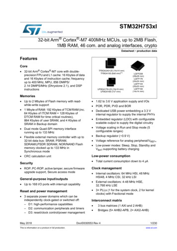
STM32G070CB/KB/RBDescriptionFigure 1. Block diagramSWCLKSWDIOas AFPOWERDMAMUXSWDDMAVDDIO1VDDAFlash memoryVDD128 KBNVICIOPORTBus matrixCPUCORTEX-M0 fmax 64 MHzVoltageregulatorVCOREI/FSRAM36 esetIntPOR/PDRNRSTT sensorRC 16 MHzPLLPCLKPLLRCLKPA[15:0]Port ALSIPB[15:0]Port BPC[15:0]Port CPD[9:0]Port DPF4,3,1,0Port F59 AFdecoderGPIOsPLLXTAL OSC4-48 MHzRC 32 kHzHSEIWDGCRCRCCI/FLSEAHBReset & clock controlEXTIOSC INOSC OUTVDDVBATLow-voltagedetectorLSESystem andperipheralclocksXTAL32 kHzRTC, TAMPBackup regsI/FAHB-to-APBOSC32 INOSC32 OUTRTC OUTRTC REFINRTC TSTAMP INVREF TIM16 channelsBRK, ETR input as AFTIM34 ch., ETR as AFTIM141 channel as AFTIM152 channels as AFTIM16 &17TIMER16/171 channel as AFI/FSYSCFGAPBMOSI/SDMISO/MCKSCK/CKNSS/WS as AFADCSPI1/I2STIM6TIM7MOSI, MISO,SCK, NSS,as AFSPI2SCL, SDA, SMBA,SMBUS as AFI2C1SCL, SDA as AFI2C2APB16x INPWRCTRLWWDGDBGMCUPower domain of analog blocks :VBATVDDVDDAIR OUT as AFUSART1&2USART1/2RX, TX,CTS, RTS,CK as AFUSART3&4USART3/4RX, TX,CTS, RTS,CK as AFVDDIO1MSv42183V1DS12766 Rev 211/9328
Functional overviewSTM32G070CB/KB/RB3Functional overview3.1Arm Cortex -M0 core with MPUThe Cortex-M0 is an entry-level 32-bit Arm Cortex processor designed for a broad range ofembedded applications. It offers significant benefits to developers, including: a simple architecture, easy to learn and program ultra-low power, energy-efficient operation excellent code density deterministic, high-performance interrupt handling upward compatibility with Cortex-M processor family platform security robustness, with integrated Memory Protection Unit (MPU).The Cortex-M0 processor is built on a highly area- and power-optimized 32-bit core, with a2-stage pipeline Von Neumann architecture. The processor delivers exceptional energyefficiency through a small but powerful instruction set and extensively optimized design,providing high-end processing hardware including a single-cycle multiplier.The Cortex-M0 processor provides the exceptional performance expected of a modern32-bit architecture, with a higher code density than other 8-bit and 16-bit microcontrollers.Owing to embedded Arm core, the STM32G070CB/KB/RB devices are compatible with Armtools and software.The Cortex-M0 is tightly coupled with a nested vectored interrupt controller (NVIC)described in Section 3.13.1.3.2Memory protection unitThe memory protection unit (MPU) is used to manage the CPU accesses to memory toprevent one task to accidentally corrupt the memory or resources used by any other activetask.The MPU is especially helpful for applications where some critical or certified code has to beprotected against the misbehavior of other tasks. It is usually managed by an RTOS (realtime operating system). If a program accesses a memory location that is prohibited by theMPU, the RTOS can detect it and take action. In an RTOS environment, the kernel candynamically update the MPU area setting, based on the process to be executed.The MPU is optional and can be bypassed for applications that do not need it.3.3Embedded Flash memorySTM32G070CB/KB/RB devices feature 128 Kbytes of embedded Flash memory availablefor storing code and data.12/93DS12766 Rev 2
STM32G070CB/KB/RBFunctional overviewFlexible protections can be configured thanks to option bytes: Readout protection (RDP) to protect the whole memory. Three levels are available:–Level 0: no readout protection
Calendar RTC with alarm and periodic wakeup from Stop/Standby Communication interfaces -Two I2C-bus interfaces supporting Fast-mode Plus (1 Mbit/s) with extra current sink, one supporting SMBus/PMBus and wakeup from Stop mode - Four USARTs with master/slave synchronous SPI; two supporting ISO7816 interface, LIN, IrDA capability, auto baud