Transcription
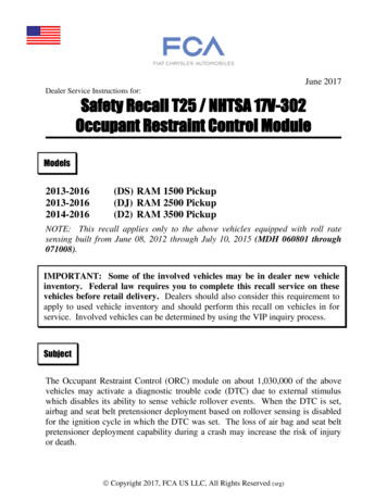
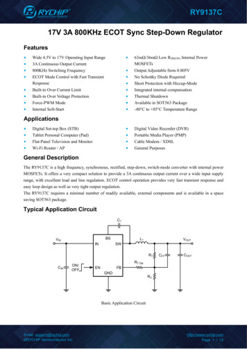
RY9137C17V 3A 800KHz ECOT Sync Step-Down RegulatorFeatures Wide 4.5V to 17V Operating Input Range3A Continuous Output Current800KHz Switching FrequencyECOT Mode Control with Fast TransientResponse Built-in Over Current LimitBuilt-in Over Voltage ProtectionForce-PWM ModeInternal Soft-Start 63mΩ/36mΩ Low RDS(ON) Internal PowerMOSFETs Output Adjustable from 0.805VNo Schottky Diode RequiredShort Protection with Hiccup-ModeIntegrated internal compensationThermal ShutdownAvailable in SOT563 Package-40 C to 85 C Temperature Range Digital Video Recorder (DVR)Portable Media Player (PMP)Cable Modem / XDSLGeneral PurposesApplications Digital Set-top Box (STB)Tablet Personal Computer (Pad)Flat-Panel Television and MonitorWi-Fi Router / APGeneral DescriptionThe RY9137C is a high frequency, synchronous, rectified, step-down, switch-mode converter with internal powerMOSFETs. It offers a very compact solution to provide a 3A continuous output current over a wide input supplyrange, with excellent load and line regulation. ECOT control operation provides very fast transient response andeasy loop design as well as very tight output regulation.The RY9137C requires a minimal number of readily available, external components and is available in a spacesaving SOT563 package.Typical Application CircuitC1BSVININSWL1VOUTR1CINON/OFFCFFCOUTRT Opt.ENFBGNDR2Basic Application CircuitEmail: support@rychip.com RYCHIP Semiconductor Inc.http://www.rychip.comPage 1 / 13
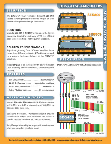
RY9137C17V 3A 800KHz ECOT Sync Step-Down RegulatorPin DescriptionPin ConfigurationTOP VIEWIN 16 FBSW 25 ENGND 34 BSSOT563Top Marking: EPYLL (device code: EP, Y year code, LL lot number code)Pin DescriptionPinNameFunction1INPower Supply Pin2SWSwitching Pin3GND4BSBootstrap. A capacitor connected between SW and BS pins is required to form afloating supply across the high-side switch driver.5ENDrive this pin to a logic-high to enable the IC. Drive to a logic-low to disable theIC and enter micro-power shutdown mode.6FBAdjustable Version Feedback input. Connect FB to the center point of the externalresistor dividerGround PinOrder Information (1)MarkingPart No.ModelDescriptionPackageT/R QtyEPYLL70301372RY9137CRY9137C ECOT Buck, 4.5-17V, 3A,SOT563800KHz, VFB 0.805V, SOT5635000PCSNote (1): All RYCHIP parts are Pb-Free and adhere to the RoHS directive.Email: support@rychip.com RYCHIP Semiconductor Inc.http://www.rychip.comPage 2 / 13
RY9137C17V 3A 800KHz ECOT Sync Step-Down RegulatorSpecificationsAbsolute Maximum Ratings (1) (2)ItemMinMaxUnitVIN voltage-0.319VEN voltage-0.319VSW voltage-0.3VIN 0.5VVBS voltage-0.3Vsw 5VV–0.36VFB voltagePower dissipationInternally Limited(3)Operating junction temperature, TJ-40150 CStorage temperature, Tstg–55150 C260 CLead Temperature (Soldering, 10sec.)Note (1): Exceeding these ratings may damage the device.Note (2): The device is not guaranteed to function outside of its operating conditions.Note (3): The maximum allowable power dissipation is a function of the maximum junction temperature, TJ(MAX),the junction-to-ambient thermal resistance, RθJA, and the ambient temperature, TA. The maximum allowable powerdissipation at any ambient temperature is calculated using: PD (MAX) (TJ(MAX) TA)/RθJA. Exceeding the maximumallowable power dissipation causes excessive die temperature, and the regulator goes into thermal shutdown.Internal thermal shutdown circuitry protects the device from permanent damage. Thermal shutdown engages atTJ 160 C (typical) and disengages at TJ 130 C (typical).ESD RatingsItemDescriptionValueUnitV(ESD-HBM)Human Body Model (HBM)ANSI/ESDA/JEDEC JS-001-2014Classification, Class: 2 2000VV(ESD-CDM)Charged Device Mode (CDM)ANSI/ESDA/JEDEC JS-002-2014Classification, Class: C0b 200VILATCH-UPJEDEC STANDARD NO.78E APRIL 2016Temperature Classification, 150Class: ImARecommended Operating ConditionsItemMinMaxUnit–40125 COperating temperature range-4085 CInput voltage VIN4.517VOutput current03AOperating junction temperature(1)Note (1): All limits specified at room temperature (TA 25 C) unless otherwise specified. All room temperaturelimits are 100% production tested. All limits at temperature extremes are ensured through correlation using standardEmail: support@rychip.com RYCHIP Semiconductor Inc.http://www.rychip.comPage 3 / 13
RY9137C17V 3A 800KHz ECOT Sync Step-Down RegulatorStatistical Quality Control (SQC) methods. All limits are used to calculate Average Outgoing Quality Level (AOQL).Thermal o-ambient thermal resistance155 C/WRθJC(top)Junction-to-case (top) thermal resistance55 C/WRθJBJunction-to-board thermal resistance30 C/WψJTJunction-to-top characterization parameter2.5 C/WψJBJunction-to-board characterization parameter31 C/W(1)(2)Note (1): The package thermal impedance is calculated in accordance to JESD 51-7.Note (2): Thermal Resistances were simulated on a 4-layer, JEDEC board.Electrical Characteristics (1) (2)VIN 12V, TA 25 C, unless otherwise specified.ParameterTest ConditionsInput Voltage RangeMinTyp.4.5Supply Current (Quiescent)VEN 3.0VSupply Current (Shutdown)VEN 0 or EN GNDFeedback ide Switch On-ResistanceISW 100mA63mΩLow-Side Switch On-ResistanceISW -100mA36mΩValley Switch Current Limit4AOver Voltage Protection Threshold19VSwitching Frequency800KHz94%89nSMaximum Duty CycleVFB 90%Minimum Off-TimeEN Rising Threshold1.4VEN Falling ThresholdWake up VIN VoltageUnder-Voltage Lockout ThresholdShutdown VIN Voltage4.3V4.5V3.8V500mVSoft Start1.5mSThermal Shutdown160 Thermal Hysteresis30 Hysteresis VIN voltage3.61Note (1): MOSFET on-resistance specifications are guaranteed by correlation to wafer level measurements.Note (2): Thermal shutdown specifications are guaranteed by correlation to the design and characteristics analysis.Email: support@rychip.com RYCHIP Semiconductor Inc.http://www.rychip.comPage 4 / 13
RY9137C17V 3A 800KHz ECOT Sync Step-Down RegulatorTypical Performance Characteristics (1) (2)Note (1): Performance waveforms are tested on the evaluation board.Note (2): VIN 12V, VOUT 3.3V, TA 25ºC, unless otherwise noted.Efficiency vs Load CurrentLoad RegulationLine RegulationVOUT 5V, 3.3V, 1.2VVOUT 5V, 3.3V, 1.2VVOUT 3.3VOutput Ripple VoltageOutput Ripple VoltageOutput Ripple VoltageVIN 12V, VOUT 3.3V, IOUT 0AVIN 12V, VOUT 3.3V, IOUT 1.5AVIN 12V, VOUT 3.3V, IOUT 3ALoop ResponseOutput ShortShort Circuit EntryVIN 12V, VOUT 3.3V, IOUT 1.5A-3AVIN 12V, VOUT 3.3VVIN 12V, VOUT 3.3VEmail: support@rychip.com RYCHIP Semiconductor Inc.http://www.rychip.comPage 5 / 13
RY9137C17V 3A 800KHz ECOT Sync Step-Down RegulatorShort Circuit RecoveryEnable Startup at No LoadEnable Shutdown at No LoadVIN 12V, VOUT 3.3VVIN 12V, VOUT 3.3V, IOUT 0AVIN 12V, VOUT 3.3V, IOUT 0AEnable Startup at Full LoadEnable Shutdown at Full LoadPower Up at No LoadVIN 12V, VOUT 3.3V, IOUT 3AVIN 12V, VOUT 3.3V, IOUT 3AVIN 12V, VOUT 3.3V, IOUT 0APower Up at Full LoadVIN 12V, VOUT 3.3V, IOUT 3AEmail: support@rychip.com RYCHIP Semiconductor Inc.http://www.rychip.comPage 6 / 13
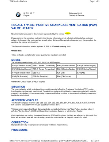
RY9137C17V 3A 800KHz ECOT Sync Step-Down RegulatorFunctional Block ferenceRipple GenSWDriverOCOCLReferenceSWGNDBlock DiagramFunctions DescriptionInternal RegulatorThe RY9137C is a current mode step down DC/DC converter that provides excellent transient response with noextra external compensation components. This device contains an internal, low resistance, high voltage powerMOSFET, and operates at a high 800KHz operating frequency to ensure a compact, high efficiency design withexcellent AC and DC performance.Error AmplifierThe error amplifier compares the FB pin voltage with the internal FB reference (VFB) and outputs a currentproportional to the difference between the two. This output current is then used to charge or discharge the internalcompensation network, which is used to control the power MOSFET current. The optimized internal compensationnetwork minimizes the external component counts and simplifies the control loop design.Under-Voltage Lockout (UVLO)Under-voltage lockout (UVLO) protects the chip from operating at an insufficient supply voltage. UVLO protectionmonitors the internal regulator voltage. When the voltage is lower than UVLO threshold voltage, the device is shutoff. When the voltage is higher than UVLO threshold voltage, the device is enabled again.Thermal ShutdownThermal shutdown prevents the chip from operating at exceedingly high temperatures. When the silicon dietemperature exceeds 160 C, it shuts down the whole chip. When the temperature falls below its lower threshold(Typ. 130 C) the chip is enabled again.Email: support@rychip.com RYCHIP Semiconductor Inc.http://www.rychip.comPage 7 / 13
RY9137C17V 3A 800KHz ECOT Sync Step-Down RegulatorInternal Soft-StartThe soft-start is implemented to prevent the converter output voltage from overshooting during startup. When thechip starts, the internal circuitry generates a soft-start voltage (SS) ramping up from 0V to 0.805V. When it is lowerthan the internal reference (REF), SS overrides REF so the error amplifier uses SS as the reference. When SS ishigher than REF, REF regains control. The SS time is internally max to 1.5ms.Over Current Protection and HiccupThe RY9137C has cycle-by-cycle over current limit when the inductor current peak value exceeds the set currentlimit threshold. Meanwhile, output voltage starts to drop until FB is below the Under-Voltage (UV) threshold. Oncea UV is triggered, the RY9137C enters hiccup mode to periodically restart the part. This protection mode isespecially useful when the output is dead-short to ground. The average short circuit current is greatly reduced toalleviate the thermal issue and to protect the regulator. The RY9137C exits the hiccup mode once the over currentcondition is removed.Startup and ShutdownIf both VIN and EN are higher than their appropriate thresholds, the chip starts. The reference block starts first,generating stable reference voltage and currents, and then the internal regulator is enabled. The regulator providesstable supply for the remaining circuitries. Three events can shut down the chip: EN low, VIN low and thermalshutdown. In the shutdown procedure, the signaling path is first blocked to avoid any fault triggering. The compvoltage and the internal supply rail are then pulled down. The floating driver is not subject to this shutdowncommand.Email: support@rychip.com RYCHIP Semiconductor Inc.http://www.rychip.comPage 8 / 13
RY9137C17V 3A 800KHz ECOT Sync Step-Down RegulatorApplications InformationSetting the Output VoltageRY9137C require an input capacitor, an output capacitor and an inductor. These components are critical to theperformance of the device. RY9137C are internally compensated and do not require external components to achievestable operation. The output voltage can be programmed by resistor divider.𝑉𝑉𝑂𝑂𝑂𝑂𝑂𝑂 𝑉𝑉𝐹𝐹𝐹𝐹 VOUT(V)R1(KΩ)R2(KΩ)RT(KΩ)L1(μH)1.02.4210Non or 01.053.04101.24.911.5𝑅𝑅1 𝑅𝑅2𝑅𝑅2C1(nF)CIN(μF)COUT(μF)CFF (pF) Opt.1.51002222 2CFF ChapterNon or 01.51002222 2CFF Chapter10Non or 01.51002222 2CFF Chapter8.6310Non or 02.21002222 2CFF Chapter1.812.3610Non or 02.21002222 2CFF Chapter2.521.0610Non or 02.21002222 2CFF Chapter3.330.9910Non or 02.21002222 2CFF Chapter5.052.1110Non or 02.21002222 2CFF ChapterAll the external components are the suggested values, the final values are based on the application testing results.Selecting the InductorThe recommended inductor values are shown in the Application Diagram. It is important to guarantee the inductorcore does not saturate during any foreseeable operational situation. The inductor should be rated to handle themaximum inductor peak current: Care should be taken when reviewing the different saturation current ratings thatare specified by different manufacturers. Saturation current ratings are typically specified at 25 C, so ratings atmaximum ambient temperature of the application should be requested from the manufacturer. The inductor valuecan be calculated with:𝐿𝐿 𝑉𝑉𝑂𝑂𝑂𝑂𝑂𝑂 (𝑉𝑉𝐼𝐼𝐼𝐼 𝑉𝑉𝑂𝑂𝑂𝑂𝑂𝑂 )𝑉𝑉𝐼𝐼𝐼𝐼 𝐼𝐼𝐿𝐿 𝐹𝐹𝑂𝑂𝑂𝑂𝑂𝑂Where ΔIL is the inductor ripple current. Choose inductor ripple current to be approximately 30% to 40% of themaximum load current. The maximum inductor peak current can be estimated as:𝐼𝐼𝐿𝐿(𝑀𝑀𝑀𝑀𝑀𝑀) 𝐼𝐼𝐿𝐿𝐿𝐿𝐿𝐿𝐿𝐿 𝐼𝐼𝐿𝐿2Under light load conditions below 100mA, larger inductance is recommended for improved efficiency. Largerinductances lead to smaller ripple currents and voltages, but they also have larger physical dimensions, lowersaturation currents and higher linear impedance. Therefore, the choice of inductance should be compromisedaccording to the specific application.Email: support@rychip.com RYCHIP Semiconductor Inc.http://www.rychip.comPage 9 / 13
RY9137C17V 3A 800KHz ECOT Sync Step-Down RegulatorSelecting the Input CapacitorThe input current to the step-down converter is discontinuous and therefore requires a capacitor to supply AC currentto the step-down converter while maintaining the DC input voltage. For a better performance, use ceramic capacitorsplaced as close to VIN as possible and a 0.1µF input capacitor to filter out high frequency interference isrecommended. Capacitors with X5R and X7R ceramic dielectrics are recommended because they are stable withtemperature fluctuations.The capacitors must also have a ripple current rating greater than the maximum input ripple current of the converter.The input ripple current can be estimated with �𝐶 𝐼𝐼𝑂𝑂𝑈𝑈𝑇𝑇 1 om the above equation, it can be concluded that the input ripple current reaches its maximum at VIN 2VOUT where𝐼𝐼. For simplification, choose an input capacitor with an RMS current rating greater than half of theI𝐶𝐶𝐶𝐶𝐶𝐶 𝑂𝑂𝑂𝑂𝑂𝑂2maximum load current.The input capacitance value determines the input voltage ripple of the converter. If there is an input voltage ripplerequirement in the system, choose the input capacitor that meets the specification. The input voltage ripple can beestimate with Equation: 𝑉𝑉𝐼𝐼𝐼𝐼 ��𝑂𝑂𝑂𝑉𝑉𝑂𝑂𝑂𝑂𝑂𝑂 1 𝐹𝐹𝑂𝑂𝑂𝑂𝑂𝑂 ��𝑉𝐼𝐼𝐼𝐼Similarly, when VIN 2VOUT, input voltage ripple reaches its maximum of 𝑉𝑉𝐼𝐼𝐼𝐼 Selecting the Output ��𝑂𝑂𝑂𝑂 𝐶𝐶𝐼𝐼𝐼𝐼 𝐹𝐹An output capacitor is required to maintain the DC output voltage. The output voltage ripple can be estimated withEquation: 𝑉𝑉𝑂𝑂𝑂𝑂𝑂𝑂 ��𝑂𝑂𝑂1 1 𝑅𝑅𝐸𝐸𝐸𝐸𝐸𝐸 𝐹𝐹𝑂𝑂𝑂𝑂𝑂𝑂 𝐿𝐿𝑉𝑉𝐼𝐼𝐼𝐼8 𝐹𝐹𝑂𝑂𝑂𝑂𝑂𝑂 𝐶𝐶𝑂𝑂𝑂𝑂𝑂𝑂There are some differences between different types of capacitors. In the case of ceramic capacitors, the impedanceat the switching frequency is dominated by the capacitance. The output voltage ripple is mainly caused by thecapacitance. For simplification, the output voltage ripple can be estimated with Equation: 𝑉𝑉𝑂𝑂𝑂𝑂𝑂𝑂 𝑉𝑉𝑂𝑂𝑂𝑂𝑂𝑂28 𝐹𝐹𝑂𝑂𝑂𝑂𝑂𝑂 𝐿𝐿 𝐶𝐶𝑂𝑂𝑂𝑂𝑂𝑂 1 𝑉𝑉𝑂𝑂𝑂𝑂𝑂𝑂 𝑉𝑉𝐼𝐼𝐼𝐼A larger output capacitor can achieve a better load transient response, but the maximum output capacitor limitationshould also be considered in the design application. If the output capacitor value is too high, the output voltage willnot be able to reach the design value during the soft-start time and will fail to regulate. The maximum outputcapacitor value (COUT MAX) can be limited approximately with Equation:𝐶𝐶𝑂𝑂𝑂𝑂𝑂𝑂 𝑀𝑀𝑀𝑀𝑀𝑀 𝐼𝐼𝐿𝐿𝐿𝐿𝐿𝐿 𝐴𝐴𝐴𝐴𝐴𝐴 𝐼𝐼𝑂𝑂𝑂𝑂𝑂𝑂 𝑇𝑇𝑆𝑆𝑆𝑆 /𝑉𝑉𝑂𝑂𝑂𝑂𝑂𝑂Email: support@rychip.com RYCHIP Semiconductor Inc.http://www.rychip.comPage 10 / 13
RY9137C17V 3A 800KHz ECOT Sync Step-Down RegulatorWhere LLIM AVG is the average start-up current during the soft-start period, and TSS is the soft- start time.On the other hand, special attention should be paid when selecting these components. The DC bias of thesecapacitors can result in a capacitance value that falls below the minimum value given in the recommended capacitorspecifications table.The ceramic capacitor’s actual capacitance can vary with temperature. The capacitor type X7R, which operates overa temperature range of 55 C to 125 C, will only vary the capacitance to within 15%. The capacitor type X5Rhas a similar tolerance over a reduced temperature range of 55 C to 85 C. Many large value ceramic capacitors,larger than 1uF are manufactured with Z5U or Y5V temperature characteristics. Their capacitance can drop by morethan 50% as the temperature varies from 25 C to 85 C. Therefore, X5R or X7R is recommended over Z5U andY5V in applications where the ambient temperature will change significantly above or below 25 C.Feed-Forward Capacitor (CFF)RY9137C has internal loop compensation, so adding CFF is optional. Specifically, for specific applications, ifnecessary, consider whether to add feed-forward capacitors according to the situation.The use of a feed-forward capacitor (CFF) in the feedback network is to improve the transient response or higherphase margin. For optimizing the feed-forward capacitor, knowing the cross frequency is the first thing. The crossfrequency (or the converter bandwidth) can be determined by using a network analyzer. When getting the crossfrequency with no feed-forward capacitor identified, the value of feed-forward capacitor (CFF) can be calculatedwith the following equation:𝐶𝐶𝐹𝐹𝐹𝐹 1111 𝑅𝑅12𝜋𝜋 ��𝑅1 𝑅𝑅2Where FCROSS is the cross frequency.To reduce transient ripple, the feed-forward capacitor value can be increased to push the cross frequency to higherregion. Although this can improve transient response, it also decreases phase margin and cause more ringing. In theother hand, if more phase margin is desired, the feed-forward capacitor value can be decreased to push the crossfrequency to lower region.Email: support@rychip.com RYCHIP Semiconductor Inc.http://www.rychip.comPage 11 / 13
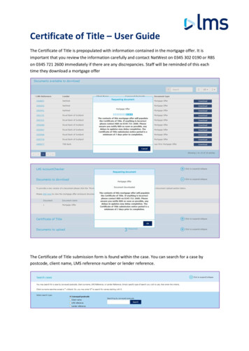
RY9137C17V 3A 800KHz ECOT Sync Step-Down RegulatorPC Board Layout ConsiderationPCB layout is very important to achieve stable operation. It is highly recommended to duplicate EVB layout foroptimum performance. If change is necessary, please follow these guidelines for reference.1. Keep the path of switching current short and minimize the loop area formed by Input capacitor, high-sideMOSFET and low-side MOSFET.2. Bypass ceramic capacitors are suggested to be put close to the VIN Pin.3. Ensure all feedback connections are short and direct. Place the feedback resistors and compensationcomponents as close to the chip as possible.4. VOUT, SW away from sensitive analog areas such as FB.5. Connect IN, SW, and especially GND respectively to a large copper area to cool the chip to improve thermalperformance and long-term reliability.Top LayerBottom LayerSample Board LayoutEmail: support@rychip.com RYCHIP Semiconductor Inc.http://www.rychip.comPage 12 / 13
RY9137C17V 3A 800KHz ECOT Sync Step-Down RegulatorPackage DescriptionEmail: support@rychip.com RYCHIP Semiconductor Inc.http://www.rychip.comPage 13 / 13
17V 3A 800KHz ECOT Sync Step-Down Regulator Page 1 / 13 Features Wide 4.5V to 17V Operating Input Range 3A Continuous Output Current . Top Marking: EPYLL (device code: EP, Y year code, LL lot number code) Pin Description : Pin Name Function : 1 IN Power Supply Pin 2 SW Switching Pin 3 : GND : Ground Pin : 4 . BS ;