Transcription
CYUSB301X/CYUSB201XEZ-USB FX3: SuperSpeed USB ControllerFeatures ApplicationsUniversal serial bus (USB) integration USB 3.1, Gen 1 and USB 2.0 peripherals compliant with USB3.1 Specification Revision 1.0 (TID # 340800007) 5-Gbps SuperSpeed PHY compliant with USB 3.1 Gen 1 High-speed On-The-Go (HS-OTG) host and peripheralcompliant with OTG Supplement Version 2.0 Thirty-two physical endpoints Support for battery charging Specification 1.1 and accessorycharger adaptor (ACA) detection Digital video camcorders Digital still cameras Printers Scanners Video capture cards Test and measurement equipmentGeneral Programmable Interface (GPIF II) Programmable 100-MHz GPIF II enables connectivity to awide range of external devices 8-, 16-, 24-, and 32-bit data bus Up to16 configurable control signals Surveillance cameras Personal navigation devices Medical imsaging devices Video IP phones Portable media players Industrial cameras Data loggers Data acquisition High-performance Human Interface Devices (gesturerecognition)Fully accessible 32-bit CPU ARM926EJ core with 200-MHz operation 512-KB or 256-KB embedded SRAMAdditional connectivity to the following peripherals SPI master at up to 33 MHz UART support of up to 4 Mbps2 I C master controller at 1 MHz2 I S master (transmitter only) at sampling frequencies of32 kHz, 44.1 kHz, and 48 kHz Selectable clock input frequencies 19.2, 26, 38.4, and 52 MHz 19.2-MHz crystal input support Ultra low-power in core power-down mode Less than 60 µA with VBATT on and 20 µA with VBATT off Independent power domains for core and I/O Core operation at 1.2 V I2S, UART, and SPI operation at 1.8 to 3.3 V2 I C operation at 1.2 V to 3.3 V Package options 121-ball, 10- 10-mm, 0.8-mm pitch Pb-free ball grid array(BGA) 131-ball, 4.7- 5.1-mm, 0.4-mm pitch wafer-level chip scalepackage (WLCSP) See Table 20 for details on the eight FX3 variants For a complete list of related documentation, click here.EZ-USB Software Development Kit (SDK) for code development of firmware and PC Applications Includes RTOS Framework (using ThreadX Version 5) Firmware examples covering all I/O modules Visual Studio host examples using C and C#SuperSpeed Explorer Board available for rapid prototyping Several accessory boards also available: Adapter boards for Xilinx/Altera FPGA development Adapter board for Video development CPLD board for concept testing and initial developmentCypress Semiconductor CorporationDocument Number: 001-52136 Rev. *R 198 Champion Court San Jose, CA 95134-1709 408-943-2600Revised March 27, 2015
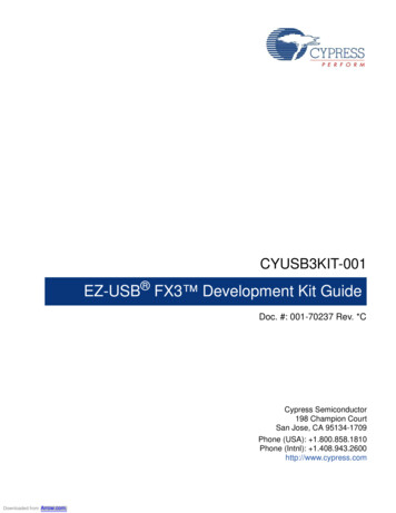
CYUSB301X/CYUSB201XLogic Block DiagramDocument Number: 001-52136 Rev. *RPage 2 of 52
CYUSB301X/CYUSB201XMore InformationCypress provides a wealth of data at www.cypress.com to help you to select the right product device for your design, and to helpyou to quickly and effectively integrate the device into your design. For a comprehensive list of resources, see the knowledge basearticle KBA87889, How to design with FX3/FX3S. Overview: USB Portfolio, USB RoadmapUSB 3.0 Product Selectors: FX3, FX3S, CX3, HX3, WestBridge BeniciaApplication notes: Cypress offers a large number of USB application notes covering a broad range of topics, from basic toadvanced level. Recommended application notes for gettingstarted with FX3 are: AN75705 - Getting Started with EZ-USB FX3 AN76405 - EZ-USB FX3 Boot Options AN70707 - EZ-USB FX3/FX3S Hardware Design Guidelinesand Schematic Checklist AN65974 - Designing with the EZ-USB FX3 Slave FIFO Interface AN75779 - How to Implement an Image Sensor Interface withEZ-USB FX3 in a USB Video Class (UVC) Framework AN86947 - Optimizing USB 3.0 Throughput with EZ-USBFX3 AN84868 - Configuring an FPGA over USB Using CypressEZ-USB FX3 AN68829 - Slave FIFO Interface for EZ-USB FX3: 5-Bit Address ModeAN73609 - EZ-USB FX2LP/ FX3 Developing Bulk-Loop Example on Linux AN77960 - Introduction to EZ-USB FX3 High-Speed USBHost Controller AN76348 - Differences in Implementation of EZ-USB FX2LPand EZ-USB FX3 Applications AN89661 - USB RAID 1 Disk Design Using EZ-USB FX3S Code Examples: Modify as required USB Hi-Speed USB Full-Speed USB SuperSpeed Technical Reference Manual (TRM): EZ-USB FX3 Technical Reference Manual Development Kits: CYUSB3KIT-003, EZ-USB FX3 SuperSpeed Explorer Kit CYUSB3KIT-001, EZ-USB FX3 Development Kit Models: IBISEZ-USB FX3 Software Development KitCypress delivers the complete software and firmware stack for FX3, in order to easily integrate SuperSpeed USB into any embeddedapplication. The Software Development Kit (SDK) comes with tools, drivers and application examples, which help accelerate application development.GPIF II DesignerThe GPIF II Designer is a graphical software that allows designers to configure the GPIF II interface of the EZ-USB FX3 USB 3.0Device Controller.The tool allows users the ability to select from one of five Cypress supplied interfaces, or choose to create their own GPIF II interfacefrom scratch. Cypress has supplied industry standard interfaces such as Asynchronous and Synchronous Slave FIFO, Asynchronousand Synchronous SRAM, and Asynchronous SRAM. Designers who already have one of these pre-defined interfaces in their systemcan simply select the interface of choice, choose from a set of standard parameters such as bus width (x8, 16, x32) endianess, clocksettings, and compile the interface. The tool has a streamlined three step GPIF interface development process for users who need acustomized interface. Users are able to first select their pin configuration and standard parameters. Secondly, they can design a virtualstate machine using configurable actions. Finally, users can view output timing to verify that it matches the expected timing. Once thethree step process is complete, the interface can be compiled and integrated with FX3.Document Number: 001-52136 Rev. *RPage 3 of 52
CYUSB301X/CYUSB201XContentsFunctional Overview .5Application Examples .5USB Interface .6OTG .6ReNumeration .7EZ-Dtect .7VBUS Overvoltage Protection .7Carkit UART Mode .7GPIF II .8CPU .8JTAG Interface .8Other Interfaces .8SPI Interface .8UART Interface .9I2C Interface .9I2S Interface .9Boot Options .9Reset .9Hard Reset .9Soft Reset .9Clocking .1032-kHz Watchdog Timer Clock Input .10Power .10Power Modes .11Digital I/Os .13GPIOs .13System-level ESD .13Document Number: 001-52136 Rev. *RPin Configurations .14Pin Description .15Electrical Specifications .19Absolute Maximum Ratings .19Operating Conditions .19DC Specifications .19AC Timing Parameters .21GPIF II Timing .21Slave FIFO Interface .24Host Processor Interface (P-Port) Timing .30Serial Peripherals Timing .37Reset Sequence .42Package Diagram .43Ordering Information .45Ordering Code Definitions .45Acronyms .46Document Conventions .46Units of Measure .46Errata .47Qualification Status .47Errata Summary .47Document History Page .49Sales, Solutions, and Legal Information .52Worldwide Sales and Design Support .52Products .52PSoC Solutions .52Cypress Developer Community .52Technical Support .52Page 4 of 52
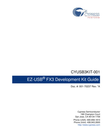
CYUSB301X/CYUSB201XFunctional OverviewCypress’s EZ-USB FX3 is a SuperSpeed peripheral controller,providing integrated and flexible features.FX3 has a fully configurable, parallel, general programmableinterface called GPIF II, which can connect to any processor,ASIC, or FPGA. GPIF II is an enhanced version of the GPIF inFX2LP, Cypress’s flagship USB 2.0 product. It provides easy andglueless connectivity to popular interfaces, such asasynchronous SRAM, asynchronous and synchronous addressdata multiplexed interfaces, and parallel ATA.FX3 has integrated the USB 3.1 Gen 1 and USB 2.0 physicallayers (PHYs) along with a 32-bit ARM926EJ-S microprocessorfor powerful data processing and for building customapplications. It implements an architecture that enables375-MBps data transfer from GPIF II to the USB interface.An integrated USB 2.0 OTG controller enables applications inwhich FX3 may serve dual roles; for example, EZ-USB FX3 mayfunction as an OTG Host to MSC as well as HID-class devices.FX3 contains 512 KB or 256 KB of on-chip SRAM (see OrderingInformation on page 45) for code and data. EZ-USB FX3 alsoprovides interfaces to connect to serial peripherals such asUART, SPI, I2C, and I2S.FX3 comes with application development tools. The softwaredevelopment kit comes with firmware and host applicationexamples for accelerating time to market.FX3 complies with the USB 3.1, Gen 1.0 specification and is alsobackward compatible with USB 2.0. It also complies with theBattery Charging Specification v1.1 and USB 2.0 OTGSpecification v2.0.Application ExamplesIn a typical application (see Figure 1), the FX3 functions as themain processor running the application software that connectsexternal hardware to the SuperSpeed USB connection.Additionally, FX3 can function as a coprocessor connecting viathe GPIF II interface to an application processor (see Figure 2)and operates as a subsystem providing SuperSpeed USBconnectivity to the application processor.Figure 1. EZ-USB FX3 as Main ProcessorCrystal*ClockUSBHostUSBEz-USB FX3GPIF IIExternal SlaveDevice(e.g. ImageSensor)I 2C* A clock input may be provided on theCLKIN pin instead of a crystal inputDocument Number: 001-52136 Rev. *REEPROMPage 5 of 52
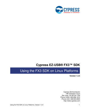
CYUSB301X/CYUSB201XFigure 2. EZ-USB FX3 as a CoprocessorCrystal*ClockUSBHostUSBEz-USB FX3GPIF IIExternal Master(e.g. MCU/CPU/FPGA/ASIC)I 2C* A clock input may be provided on theCLKIN pin instead of a crystal inputEEPROMUSB InterfaceOTGFX3 complies with the following specifications and supports thefollowing features:FX3 is compliant with the OTG Specification Revision 2.0. InOTG mode, FX3 supports both A and B device modes andsupports Control, Interrupt, Bulk, and Isochronous datatransfers. Supports USB peripheral functionality compliant with USB 3.1Specification Revision 1.0 and is also backward compatiblewith the USB 2.0 Specification. FX3 Hi-Speed parts (CYUSB201X) only support USB 2.0. Complies with OTG Supplement Revision 2.0. It supportsHigh-Speed, Full-Speed, and Low-Speed OTG dual-role devicecapability. As a peripheral, FX3 is capable of SuperSpeed,High-Speed, and Full-Speed. As a host, it is capable ofHigh-Speed, Full-Speed, and Low-Speed. Supports Carkit Pass-Through UART functionality on USBD /D– lines based on the CEA-936A specification. Supports 16 IN and 16 OUT endpoints. Supports the USB 3.0 Streams feature. It also supports USBAttached SCSI (UAS) device-class to optimize mass-storageaccess performance. As a USB peripheral, application examples show that the FX3supports UAS, USB Video Class (UVC), and Mass StorageClass (MSC) USB peripheral classes. All other device classescan be supported by customer firmware; a template exampleis provided as a starting point. As an OTG host, application examples show that FX3 supportsMSC and HID device classes.FX3 requires an external charge pump (either standalone orintegrated into a PMIC) to power VBUS in the OTG A-devicemode.The Target Peripheral List for OTG host implementation consistsof MSC- and HID-class devices.FX3 does not support Attach Detection Protocol (ADP).Note When the USB port is not in use, disable the PHY andtransceiver to save power.Document Number: 001-52136 Rev. *RPage 6 of 52
CYUSB301X/CYUSB201XOTG ConnectivityIn OTG mode, FX3 can be configured to be an A, B, or dual-roledevice. It can connect to the following: ACA device Targeted USB peripheral SRP-capable USB peripheral HNP-capable USB peripheral OTG host HNP-capable host OTG deviceFX3's charger detects a dedicated wall charger, Host/Hubcharger, and Host/Hub.VBUS Overvoltage ProtectionThe maximum input voltage on FX3's VBUS pin is 6 V. A chargercan supply up to 9 V on VBUS. In this case, an externalovervoltage protection (OVP) device is required to protect FX3from damage on VBUS. Figure 3 shows the system applicationdiagram with an OVP device connected on VBUS. Refer toTable 8 for the operating range of VBUS and VBATT.Figure 3. System Diagram with OVP Device For VBUSPOWER SUBSYSTEMFX3 supports USB Charger and accessory detection (EZ-Dtect).The charger detection mechanism complies with the BatteryCharging Specification Revision 1.1. In addition to supportingthis version of the specification, FX3 also provides hardwaresupport to detect the resistance values on the ID pin.FX3 can detect the following resistance ranges: Less than 10 Less than 1 k 65 k to 72 k 35 k to 39 k 99.96 k to 104.4 k (102 k 2%) 119 k to 132 k Higher than 220 k 431.2 k to 448.8 k (440 k 2%)VIO5AVDDVDDVIO4CVDDQVIO3VIO2VBUSOTG IDOVP device2SSRXSSRX SSTXSSTX DD 3456789USB-PortEZ-DtectEZ-USB FX31USB ConnectorWhen first plugged into USB, FX3 enumerates automatically withthe Cypress Vendor ID (0x04B4) and downloads firmware andUSB descriptors over the USB interface. The downloadedfirmware executes an electrical disconnect and connect. FX3enumerates again, this time as a device defined by thedownloaded information. This patented two-step process, calledReNumeration, happens instantly when the device is plugged in.VIO1Because of FX3's soft configuration, one chip can take on theidentities of multiple distinct USB devices.U3TXVDDQU3RXVDDQReNumerationGNDCarkit UART ModeThe USB interface supports the Carkit UART mode (UART overD /D–) for non-USB serial data transfer. This mode is based onthe CEA-936A specification.In the Carkit UART mode, the output signaling voltage is 3.3 V.When configured for the Carkit UART mode, TXD of UART(output) is mapped to the D– line, and RXD of UART (input) ismapped to the D line.In the Carkit UART mode, FX3 disables the USB transceiver andD and D– pins serve as pass-through pins to connect to theUART of the host processor. The Carkit UART signals may berouted to the GPIF II interface or to GPIO[48] and GPIO[49], asshown in Figure on page 8.In this mode, FX3 supports a rate of up to 9600 bps.Figure 4. Carkit UART Pass-through Block DiagramCtrlCarkit UART Pass-throughUART TXDTXDUART RXDRXDRXD (DP)Carkit UART Pass-throughInterface on GPIOsDocument Number: 001-52136 Rev. *RUSB PHY DMMUXDPGPIO[48](UART TX)USB-Port()Carkit UART Pass-throughInterface on GPIF IITXD (DM)GPIO[49]( UART RX)Page 7 of 52
CYUSB301X/CYUSB201XGPIF IICPUThe high-performance GPIF II interface enables functionalitysimilar to, but more advanced than, FX2LP’s GPIF and SlaveFIFO interfaces.FX3 has an on-chip 32-bit, 200-MHz ARM926EJ-S core CPU.The core has direct access to 16 KB of Instruction TightlyCoupled Memory (TCM) and 8 KB of Data TCM. TheARM926EJ-S core provides a JTAG interface for firmwaredebugging.The GPIF II is a programmable state machine that enables aflexible interface that may function either as a master or slave inindustry-standard or proprietary interfaces. Both parallel andserial interfaces may be implemented with GPIF II.Here is a list of GPIF II features: Functions as master or slave Provides 256 firmware programmable states Supports 8-bit, 16-bit, 24-bit, and 32-bit parallel data bus Enables interface frequencies up to 100 MHz Supports 14 configurable control pins when a 32- bit data busis used. All control pins can be either input/output or bidirectional. Supports 16 configurable control pins when a 16/8 data bus isused. All control pins can be either input/output or bi-directional.GPIF II state transitions are based on control input signals. Thecontrol output signals are driven as a result of the GPIF II statetransitions. The INT# output signal can be controlled by GPIF II.Refer to the GPIFII Designer tool. The GPIF II state machine’sbehavior is defined by a GPIF II descriptor. The GPIF IIdescriptor is designed such that the required interface specifications are met. 8 KB of memory (separate from the 256/512 KB ofembedded SRAM) is dedicated to the GPIF II waveform wherethe GPIF II descriptor is stored in a specific format.Cypress’s GPIFII Designer Tool enables fast development ofGPIF II descriptors and includes examples for commoninterfaces.Example implementations of GPIF II are the asynchronous slaveFIFO and synchronous slave FIFO interfaces.Slave FIFO interfaceThe Slave FIFO interface signals are shown in Figure 5. Thisinterface allows an external processor to directly access up tofour buffers internal to FX3. Further details of the Slave FIFOinterface are described on page 24.Note Access to all 32 buffers is also supported over the slaveFIFO interface. For details, contact Cypress ApplicationsSupport.Figure 5. Slave FIFO InterfaceP KTENDFLAG BFLAG AA [1:0]D[31:0] Integrates 256/512 KB of embedded SRAM for code and dataand 8 KB of Instruction cache and Data cache. Implements efficient and flexible DMA connectivity between thevarious peripherals (such as, USB, GPIF II, I2S, SPI, UART,I2C), requiring firmware only to configure data accessesbetween peripherals, which are then managed by the DMAfabric. Allows easy application development using industry-standarddevelopment tools for ARM926EJ-S.Examples of the FX3 firmware are available with the CypressEZ-USB FX3 Development Kit.JTAG InterfaceFX3’s JTAG interface has a standard five-pin interface to connectto a JTAG debugger in order to debug firmware through theCPU-core's on-chip-debug circuitry.Industry-standard debugging tools for the ARM926EJ-S corecan be used for the FX3 application development.Other InterfacesFX3 supports the following serial peripherals: SPI UART I2C I2SThe SPI, UART, and I2S interfaces are multiplexed on the serialperipheral port.The CYUSB3012 and CYUSB3014 Pin List on page 15 showsdetails of how these interfaces are multiplexed. Note that whenGPIF II is configured for a 32-bit data bus width (CYUSB3012and CYUSB3014), then the SPI interface is not available.SPI InterfaceFX3 supports an SPI Master interface on the Serial Peripheralsport. The maximum operation frequency is 33 MHz.S LCS#External M aster(For exam ple,M C U/C PU/FPG A/ASIC )FX3 offers the following advantages:EZ-U SB FX3The SPI controller supports four modes of SPI communication(see SPI Timing Specification on page 40 for details on themodes) with the Start-Stop clock. This controller is asingle-master controller with a single automated SSN control. Itsupports transaction sizes ranging from four bits to 32 bits.S LW R#SLRD#S LO E#Note: M ultiple Flags m ay be configured.Document Number: 001-52136 Rev. *RPage 8 of 52
CYUSB301X/CYUSB201XBoot OptionsUART InterfaceThe UART interface of FX3 supports full-duplex communication.It includes the signals noted in Table 1.Table 1. UART Interface SignalsSignalTXRXCTSRTSDescriptionOutput signalInput signalFlow controlFlow controlThe UART is capable of generating a range of baud rates, from300 bps to 4608 Kbps, selectable by the firmware. If flow controlis enabled, then FX3's UART only transmits data when the CTSinput is asserted. In addition to this, FX3’s UART asserts the RTSoutput signal, when it is ready to receive data.FX3 can load boot images from various sources, selected by theconfiguration of the PMODE pins. Following are the FX3 bootoptions: Boot from USB Boot from I2C Boot from SPI (SPI devices supported are M25P32 (32 Mbit),M25P16 (16 Mbit), M25P80 (8 Mbit), and M25P40 (4 Mbit)) ortheir equivalents Boot from GPIF II ASync ADMux mode Boot from GPIF II Sync ADMux mode Boot from GPIF II ASync SRAM modeTable 2. FX3 Booting Options2PMODE[2:0][1]F00F01F11F0FF1F1FF0F1I C InterfaceI2CI2CFX3’sinterface is compatible with theBus SpecificationRevision 3. This I2C interface is capable of operating only as I2Cmaster; therefore, it may be used to communicate with other I2Cslave devices. For example, FX3 may boot from an EEPROMconnected to the I2C interface, as a selectable boot option.FX3’s I2C Master Controller also supports multi-master modefunctionality.The power supply for the I2C interface is VIO5, which is aseparate power domain from the other serial peripherals. Thisgives the I2C interface the flexibility to operate at a differentvoltage than the other serial interfaces.The I2C controller supports bus frequencies of 100 kHz,400 kHz, and 1 MHz. When VIO5 is 1.2 V, the maximumoperating frequency supported is 100 kHz. When VIO5 is 1.8 V,2.5 V, or 3.3 V, the operating frequencies supported are 400 kHzand 1 MHz. The I2C controller supports clock-stretching toenable slower devices to exercise flow control.Boot FromSync ADMux (16-bit)Async ADMux (16-bit)USB bootAsync SRAM (16-bit)I2C, On Failure, USB Boot is EnabledI2C onlySPI, On Failure, USB Boot is EnabledResetHard ResetThe I2C interface’s SCL and SDA signals require external pull-upresistors. The pull-up resistors must be connected to VIO5.A hard reset is initiated by asserting the Reset# pin on FX3. Thespecific reset sequence and timing requirements are detailed inFigure 30 on page 42 and Table 19 on page 42. All I/Os aretristated during a hard reset. Note however, that the on-chipbootloader has control after a hard reset and it will configure I/Osignals depending on the selected boot mode; see AN76405 EZ-USB FX3 Boot Options for more details.I2S InterfaceSoft ResetFX3 has an I2S port to support external audio codec devices.FX3 functions as I2S Master as transmitter only. The I2S interfaceconsists of four signals: clock line (I2S CLK), serial data line(I2S SD), word select line (I2S WS), and master system clock(I2S MCLK). FX3 can generate the system clock as an outputon I2S MCLK or accept an external system clock input onI2S MCLK.In a soft reset, the processor sets the appropriate bits in thePP INIT control register. There are two types of Soft Reset:The sampling frequencies supported by the I2S interface are32 kHz, 44.1 kHz, and 48 kHz. CPU Reset – The CPU Program Counter is reset. Firmwaredoes not need to be reloaded following a CPU Reset. Whole Device Reset – This reset is identical to Hard Reset. The firmware must be reloaded following a Whole DeviceReset.Note1. F indicates Floating.Document Number: 001-52136 Rev. *RPage 9 of 52
CYUSB301X/CYUSB201XClockingClock inputs to FX3 must meet the phase noise and jitter requirements specified in Table 4 on page 10.FX3 allows either a crystal to be connected between the XTALINand XTALOUT pins or an external clock to be connected at theCLKIN pin. The XTALIN, XTALOUT, CLKIN, and CLKIN 32 pinscan be left unconnected if they are not used.The input clock frequency is independent of the clock and datarate of the FX3 core or any of the device interfaces. The internalPLL applies the appropriate clock multiply option depending onthe input frequency.Crystal frequency supported is 19.2 MHz, while the externalclock frequencies supported are 19.2, 26, 38.4, and 52 MHz.Table 3. Crystal/Clock Frequency SelectionFX3 has an on-chip oscillator circuit that uses an external19.2-MHz ( 100 ppm) crystal (when the crystal option is used).An appropriate load capacitance is required with a crystal. Referto the specification of the crystal used to determine the appropriate load capacitance. The FSLC[2:0] pins must be configuredappropriately to select the crystal- or clock-frequency option. Theconfiguration options are shown in Table kFrequency19.2-MHz crystal19.2-MHz input CLK26-MHz input CLK38.4-MHz input CLK52-MHz input CLKTable 4. FX3 Input Clock SpecificationsParameterPhase 30–––100-Hz offset1-kHz offset10-kHz offset100-kHz offset1-MHz offsetMaximum frequency deviationDuty cycleOvershootUndershootRise time/fall time–––––FX3 includes a watchdog timer. The watchdog timer can be usedto interrupt the ARM926EJ-S core, automatically wake up theFX3 in Standby mode, and reset the ARM926EJ-S core. Thewatchdog timer runs a 32-kHz clock, which may be optionallysupplied from an external source on a dedicated FX3 pin.ppm%nsFX3 has the following power supply domains: IO VDDQ: This is a group of independent supply domains fordigital I/Os. The voltage level on these supplies is 1.8 V to 3.3 V.FX3 provides six independent supply domains for digital I/Oslisted as follows (see Table 7 on page 15 for details on each ofthe power domain signals): VIO1: GPIF II I/O VIO2: IO2 VIO3: IO32 VIO4: UART-/SPI/I S2 VIO5: I C and JTAG (supports 1.2 V to 3.3 V) CVDDQ: This is the supply voltage for clock and reset I/O. Itshould be either 1.8 V or 3.3 V based on the voltage level ofthe CLKIN signal. VDD: This is the supply voltage for the logic core. The nominalsupply-voltage level is 1.2 V. This supplies the core logiccircuits. The same supply must also be used for the following: AVDD: This is the 1.2-V supply for the PLL, crystal oscillator, and other core analog circuits U3TXVDDQ/U3RXVDDQ: These are the 1.2-V supply voltages for the USB 3.0 interface. VBATT/VBUS: This is the 3.2-V to 6-V battery power supplyfor the USB I/O and analog circuits. This supply powers theUSB transceiver through FX3's internal voltage regulator.VBATT is internally regulated to 3.3 V.The firmware can disable the watchdog timer. Requirements forthe optional 32-kHz clock input are listed in Table 5.Table 5. 32-kHz Clock Input RequirementsMinMaxUnitsDuty cycle4060%Frequency deviation– 200ppmRise time/fall time–200nsDocument Number: 001-52136 Rev. *RdBPower32-kHz Watchdog Timer Clock 0150703–33Page 10 of 52
CYUSB301X/CYUSB201XPower Modes FX3 supports the following power modes: Normal mode: This is the full-functional operating mode. Theinternal CPU clock and the internal PLLs are enabled in thismode. Normal operating power consumption does not exceed thesum of ICC Core max and ICC USB max (see Table 7 on page15 for current consumption specifications). The I/O power supplies VIO2, VIO3, VIO4, and VIO5 can beturned off when the corresponding interface is not in use.VIO1 cannot be turned off at any time if the GPIF II interfaceis used in the application.Low-power modes (see Table 6 on page 11): Suspend mode with USB 3.0 PHY enabled (L1) Suspend mode with USB 3.0 PHY disabled (L2) Standby mode (L3) Core power-down mode (L4)Table 6. Entry and Exit Methods for Low-Power ModesLow-Power ModeSuspend Mode withUSB 3.0 PHYEnabled (L1)Characteristics The power consumption in this mode doesnot exceed ISB1 USB 3.0 PHY is enabled and is in U3 mode(one of the suspend modes defined by theUSB 3.0 specification). This one blockalone is operational with its internal clockwhile all other clocks are shut down All I/Os maintain their previous state Power supply for the wakeup source andcore power must be retained. All otherpower domains can be turned on/offindividually The states of the configuration registers,buffer memory, and all internal RAM aremaintainedAll transactions must be completed beforeFX3 enters Suspend mode (state ofoutstanding transactions are notpreserved)Methods of Entry Fir
EZ-USB FX3 Software Development Kit Cypress delivers the complete software and firmware stack for FX 3, in order to easily integrate SuperSpeed USB into any embedde d application. The Software Development Kit (SDK) comes with tools, drivers and application examples, which help accelerate appli-cation development. GPIF II Designer