Transcription
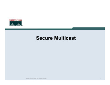
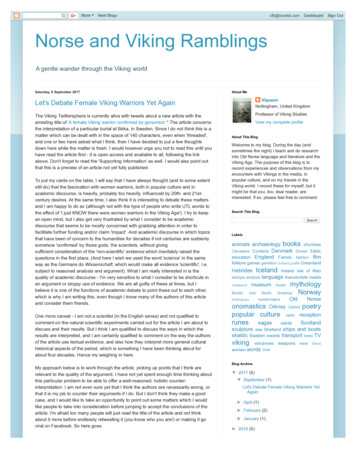
Designed, Manufactured and Supported in the USAVIKINGSECURITY & COMMUNICATION22TB-IPPRODUCTMANUALCeiling Tile SIP/MulticastTalk-Back SpeakerJanuary 7, 20212 x 2 Drop-In Ceiling Tile IP Speaker for SIP Endpoint or MulticastPaging and Making Standard and / or Emergency SIP CallsThe Viking model 22TB-IP Talk-Back 2 x 2 ceiling tile replacementspeaker enables two-way conversations and end point paging viaSIP, yet also allows for standard paging via multicast. The LineLevel Input can be used for background music. TheTalk-BackSpeaker easily connects with a single CAT5/6 cable from your PoEswitch. Its 2’ x 2’ size, shallow depth and light weight design makefor a quick and easy installation in drop/suspended ceilings. Thespeaker’s aesthetically pleasing white grill blends in with existingceiling tiles and air vents.An auxiliary switch input allows for a hard wired wall mounted buttonto initiate a SIP call. A momentary button press will initiate astandard call, and holding the button for 3 or more seconds willinitiate an emergency call. The integrated high sensitivitymicrophone enables talk-back and also monitors room noise toautomatically increase the speaker volume when necessary. Linelevel audio output connections are provided for connecting to anexternal amplifier. The 22TB-IP has an integrated 6 watt amplifierallowing its speaker output connections to directly drive up to 5Model 22TB-IPadditional analog speakers. A programmable relay output isprovided for activating door locks, strobe lights, external amplifiers,etc. A programmable blue status LED is provided to indicate paging,SIP call and network registration.!Installation requires a Network Administrator / IT TechnicianFeatures SIP compliant (see page two for compatible SIP servers and IP phone systems)Outbound Proxy, Authentification ID, Per to Peer, VLAN TaggingPoE powered (class 3, 13 Watts)Up to 28 second ID announcement (uploaded from wave file or recorded live)Paging prioritizationPlays audio from standard multicast sourcesSIP endpoint or multicast group memberLine level input for background musicAdd an optional SL-2 blue, green, red or amber strobe light (see DOD 242)Blue call status LED indicatorAutomatic Noise Canceling (ANC) feature for operation in noisy environmentsViking’s proprietary VOX switching eliminates the need for “Push to Talk” modeSelectable auto-answer feature for monitoringCompatible with Polycom multicast pagingApplications Amplified SIP endpoint or multicast IP paging for: schools, hospitals,retail stores, office spaces, etc. Provide background music and sound masking Make standard and/or emergency SIP phone calls via hands freetalkback speaker Background music and emergency calls for elevator applicationsretail stores, office spaces, etc.Information: 715-386-8861www.VikingElectronics.com Built-in high efficiency 6 Watt class D amplifierCan drive up to 5 external analog speakers for greater coverageRelay for activating door locks, strobe lights, external amplifiers, etc.SIP/Multicast: SIP page, SIP page and zoned multicast stream receiveSupport for access code to prevent unwanted SIP callsLine level audio output for connecting to an external amplifierHangs up on: busy signal, time-out, or touch tone commandNetwork remote speaker volume controlMounting: Drop mounts into 2 x2 or 2 x 4 suspended ceilingsHeavy duty back box protects speaker and circuitry against plenum dustAutomatic Gain Control (AGC) to automatically increase ring volume to compensate forambient noise Diagnostics for testing microphone, speaker and relay Programmable pre page alert toneSpecificationsPower: PoE class 3 ( 13 Watts)Dimensions: 23.75” x 23.75” x 3.75” (603.25mm x 603.25mm x 95.25mm)Shipping Weight: 8.6 lbs (3.91 kg)Operating Temperature: -40 F to 140 F (-40 C to 60 C)Humidity: 5% to 95% non-condensingSIP Audio Codecs: G711u, G722 and G711aMulticast Audio Codecs: G711u and G722 (G722 requires R8.11.1912 or higher IP firmware)Network Compliance: IEEE 802.3 af PoE, SIP 2.0 RFC3261, 100BASE-TX with auto cross overRegulatory Compliance: CE, FCC Part 15 and Canada ICES-003 Class ASensitivity: 96dB / 1W / 1M S.P. LevelMaximum Output Level: 105 dB SPL @ 1M (with no additional Speakers connected)Amplifier: 6 Watt class DConnections: (1) RJ45 10/100 Base-T, 11 gel filled butt connectors
VoIP SIP System CompatibilityFor compatibility and vendor specific detailed configuration instructions, see the Viking VoIPSIP System Compatibility List, DOD 944. To open and download this PDF file:Scan the QR code below to openand download the Viking VoIPSIP System Compatibility List1. Go to www.vikingelectronics.comand enter 944 in the search box- OR -2. Click Application Note (DOD 944)to open and download the PDFImportant: Exclusion from this list means only that compatibility has not been verified, it does not meanincompatibility. If you have questions, please call Viking Electronics at 715-386-8861.Managing Power LossesMaximum recommended length (in feet) for the number of 8 Ohm speakers on a wire pair to maintaina volume loss of less than 5dB. Once the length limit has been reached for the wire gauge used, ifadditional speakers are needed, start back at the 22TB-IP with a 2nd parallel wire run. If the length limitis reached again, start a 3rd run, etc. See DOD 895 for an example.Wire Gauge Size#162,000' 1,000'665'500'Note 1: Mount the 22TB-IP close to where theother speakers are installed to minimize thespeaker wire run lengths.400'#181,250'625'420'315'250'Note 2: Using half the recommended distanceor half as many speakers per run will keep thevolume lost limited to 3db.#20800'400'265'200'160'Note 3: Doubling up the wires will allow doublethe length, or reduce the amount of 0'60'12345Note 4: Heavier gauge wire, fewer speakersper run, and shorter runs will all minimizevolume loss.Number of 8 Ohm Speakers onEach of the Two Wire Runs2
DefinitionsClient: A computer or device that makes use of a server. As an example, the client might request a particular file from the server.DHCP: Dynamic Host Configuration Protocol. In this procedure the network server or router takes note of a client’s MAC address andassigns an IP address to allow the client to communicate with other devices on the network.DNS Server: A DNS (Domain Name System) server translates domain names (ie: www.vikingelectronics.com) into an IP address.Ethernet: Ethernet is the most commonly used LAN technology. An Ethernet Local Area Network typically uses twisted pair wires toachieve transmission speeds up to 1Gbps.Host: A computer or device connected to a network.Host Name: A host name is a label assigned to a device connected to a computer network that is used to identify the device in variousforms of network communication.Hosts File: A file stored in a computer that lists host names and their corresponding IP addresses with the purpose of mapping addressesto hosts or vice versa.Internet: A worldwide system of computer networks running on IP protocol which can be accessed by individual computers or networks.IP: Internet Protocol is the set of communications conventions that govern the way computers communicate on networks and on theInternet.IP Address: This is the address that uniquely identifies a host on a network.LAN: Local Area Network. A LAN is a network connecting computers and other devices within an office or building.Lease: The amount of time a DHCP server reserves an address it has assigned. If the address isn’t used by the host for a period oftime, the lease can expire and the address can be assigned to another host.MAC Address: MAC stands for Media Access Control. A MAC address, also called a hardware address or physical address, is a uniqueaddress assigned to a device at the factory. It resides in the device’s memory and is used by routers to send network traffic to the correctIP address. You can find the MAC address of your 22TB-IP speaker printed on a white label just above the PoE LAN port (see page 4).Router: A device that forwards data from one network to another. In order to send information to the right location, routers look at IPAddress, MAC Address and Subnet Mask.RTP: Real-Time Transport Protocol is an Internet protocol standard that specifies a way for programs to manage the real-time transmissionof multimedia data over either unicast or multicast network services.Server: A computer or device that fulfills requests from a client. This could involve the server sending a particular file requested by theclient.Session Initiation Protocol (SIP): Is a signaling communications protocol, widely used for controlling multimedia communication sessionssuch as voice and video calls over Internet Protocol (IP) networks. The protocol defines the messages that are sent between endpoints,which govern establishment, termination and other essential elements of a call.Static IP Address: A static IP Address has been assigned manually and is permanent until it is manually removed. It is not subject to theLease limitations of a Dynamic IP Address assigned by the DHCP Server. The default static IP Address is: 192.168.154.1Subnet: A portion of a network that shares a common address component. On TCP/IP networks, subnets are defined as all deviceswhose IP addresses have the same prefix. For example, all devices with IP addresses that start with 100.100.100. would be part of thesame subnet. Dividing a network into subnets is useful for both security and performance reasons. IP networks are divided using a subnetmask.TCP/IP: Transmission Control Protocol/Internet Protocol is the suite of communications protocols used to connect hosts on the Internet.TCP/IP uses several protocols, the two main ones being TCP and IP. TCP/IP is built into the UNIX operating system and is used by theInternet, making it the de facto standard for transmitting data over networks.TISP: Telephone Internet Service ProviderWAN: Wide Area Network. A WAN is a network comprising a large geographical area like a state or country. The largest WAN is theInternet.Wireless Access Point (AP): A device that allows wireless devices to connect to a wired network using Wi-Fi, or related standards. TheAP usually connects to a router (via a wired network) as a standalone device, but it can also be an integral component of the router itself.Wireless Repeater (Wireless Range Extender): takes an existing signal from a wireless router or access point and rebroadcasts it tocreate a second network. When two or more hosts have to be connected with one another over the IEEE 802.11 protocol and the distanceis too long for a direct connection to be established, a wireless repeater is used to bridge the gap.3
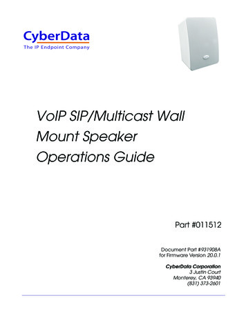
Features OverviewFront ViewBlue Call/Status LED:Flashesduring dialing, then lights steadywhen answered.Microphone: Omni-directionalmicrophone with protectivewater-resistant cloth.Speaker: 8” paper with wizzerconeBack ViewMAC Address Label: TheMAC address is a unique12 digit number used byrouters to send networktraffic to the correct IPaddress.PoE LAN Port 10/100,PoE Class 3 ( 13 Watts):Connect to your LAN viaRJ45 plug and CAT5 orgreater twisted pair wire.Optional Viking Model PA-60Paging Amplifier (DOD 493)- Connect to OptionalDoorstrike, MagLock, GateController, etc.120V ACRelayOutput Contact(2A@30VDC/ 250VAC max)Doorstrike /Magnetic Lock*NOYellowLine Out*COM(Power typically notrequired for gate l MomentarySwitch Inputto initiate or answer callsMomentary*300AE30AEUp to (15)8 OhmSpeakersUp to (15)8 OhmSpeakersUp to (15)8 OhmSpeakersGreen*35AEUp to (15)8 OhmSpeakers25AEBlack40AE *Red600 OhmPaging AudioLine InWhiteWhiteBackground MusicLine Level Audio Source (Mono)SpeakerOutUp tp (5) Optional Viking Analog Speakers,see DOD 497 and 498 (not included).See MANAGING POWER LOSSsection on page 2.* 11 Gel-Filled ButtConnectors (included)4
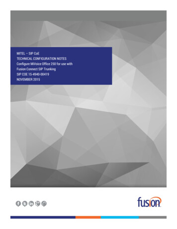
Installation and MountingRemove the existing ceiling tile, make your connections and drop in the Viking 22TB-IP 2 x 2 ceiling tile replacement speaker.If your ceiling is a 2 x 4 ft. grid, simply cut the ceiling tile in half and add a 2 ft. cross tee to support the speaker then placeremaining ceiling tile in place.Connect the 22TB-IP ceiling speaker feed supply cable through whip to connector. Make connections per wiring shown onPage 4 (Features), insulate all unused wires from each other and enclosure. When cover plate is secured, all connections/ splices and unused leads must be inside the enclosure.NOTE 1: If you are using a conduit clamp fitting other than what is provided with the 22TB-IP, loosen but do not removescrews on cover plate; push up and remove plate from assembly. Remove cable/conduit clamp fitting from plate; Install ULListed metallic enclosure entry fitting for plenum cable or flex whip.NOTE 2: AHJ / local codes may require tie-off to structure. Bend up tie-off tabs as shown below in illustration and installas directed.NOTE 3: AHJ / local codes may require tie-off to grid. Recommended fasteners; not supplied: Erico / Caddy part ATA4iand 1/4’-20 x 2” bolt, or equivalent. Install as directed.Typical Installation on SIP Based VoIP Phone System100m (328 ft) maximum*Viking22TB-IPSIP VoIP PBXorPC withSIP ServerSoftware10/100 MbpsMaximumInternetOptionalPoE Injector(If VoIP PBX doesnot have PoE)VikingsuppliesOptionalSwitch / HubCustomer’sResponsibility(Extends range of cable, keeps1 Gbps network speed for otherequipment on network)* Note: A PoE extender can be used for an additional 100 meters per extender. For longerruns (up to 2 km / 1.2 miles) a ethernet to fiber media converter can be used.5Optional Viking modelRC-4A Secure RemoteRelay Controller, seePage 23 (DOD 582)
PC Requirements IBM compatible personal computer with:Windows 7, 8 or 10 Ethernet cable (CAT5 minimum) Adobe Acrobat Reader 8 or higher 1 MB minimum free hard drive space for installation 22TB-IP hardware 16MB of free physical RAM Available LAN with PoE (class 3, 13 Watts)PC ProgrammingDownload and install the programming software1.2.3.4.Go to www.vikingelectronics.com and enter 22TB-IP in the search boxClick 22TB-IP in the search resultsScroll down the page to Downloads, click IP Programming SoftwareInstall the programming software by saving or opening the file and then clicking on setup Viking IPProgramming.exe5. Follow the prompts on your screen to complete software installation6. To start the Viking IP Programming application, click on the Viking IP Programming icon on your desktop. The Main screen will appear, allowing the user to program any 22TB-IP connected to that LAN.Note: PC must be connected to the same LAN as the 22TB-IP.A. Connect / DisconnectOpen the “Viking IP Programming” software on the PC and the start screen shown below will appear. Any Viking IP speakers thatare connected to the network will appear on the list. Simply select the 22TB-IP on the list and click on the “Connect” button at thebottom or double click the selected speaker. If no username and password have been programmed and the security code of theselected unit is still set to default (845464), the PC software will not require entering a username, password or security code toconnect to the 22TB-IP. If the 22TB-IP has been programmed with a username and password, a pop up window will ask for theusername followed by the password. If the unit’s security code has been changed from “845464”, it will then prompt for the correctsecurity code. 22TB-IP’s have a default name of “VIKING MK64 Vik02”, so if many 22TB-IP’s are connected to the same networkand all have the default name, MAC addresses must be used to identify each 22TB-IP.When finished programming, click the “Disconnect” button at the bottom. Closing the program will also automatically disconnect the unit.6
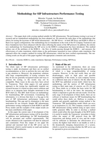
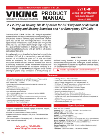
B. Configuring the 22TB-IP Network SettingsStep 1.Open the “Viking IP Programming” software on a windows PC that is connected to the same LAN as the 22TB-IP speaker to beprogrammed.Step 2.The window in the upper left corner of the menu will show you each 22TB-IP speaker that is connected to that LAN. Select the unitwith the same MAC address shown on the label located next to the Ethernet connector on the 22TB-IP speaker.Step 3.Click on the “connect” button. A default 22TB-IP has no username or password programmed, the security code is set to “845464”and when configured this way, you are instantly connected to the 22TB-IP. If the 22TB-IP has been programmed with a usernameand password, a pop up window will ask for the username followed by the password. If the unit’s security code has been changedfrom “845464”, it will then prompt for the correct security code, then click “retry”.Step 4.The program will then read and display the 22TB-IP speaker’s IP and programming settings.Step 5.Click on the “IP Settings” tab.Step 6.Select the appropriate value Static IP Settings or DHCP for “Set Unit IP Address via”. Note: changing the IP address will cause youto have to reconnect to the unit. Enter the values for the fields in “if DHCP fails” or “Static IP Settings” as needed.Step 7.Set the “Unit Name”, “Logging / Time Server Settings” as needed.Step 8.Select Peer-Peer in the “SIP Server / Peer to Peer Settings” to use the unit in Peer to Peer mode or for Multicast paging only. SelectServer to register with a SIP registrar server and fill in the “Outbnd Proxy” (SIP Outbound Proxy Server Address, “ip:port”), “Authentic.ID” (SIP Authentication ID), “Username” (SIP Username, string ), “Password” (SIP Password), and “Caller ID” (SIP Caller ID) withvalues from your VoIP provider. Required fields will be red when the unit is not registered.Example 1: On-Premise SIPPhone System(Panasonic TDE 100/200)Example 2: Cloud BasedService Provider(Voip.ms)7Example 3: Cloud BasedService Provider requiringOutbound Proxy andAuthentication ID (Ring Central)
C. Configuring 22TB-IP VLAN SettingsStep 1.Click on the “VLAN” tabStep 2.Disable or enable VLAN tagging by setting the value of “VLAN Tagging”.Step 3.Set the VLAN tag ID by selecting an integer (1 to 4094) in “ID for all packets”.Step 4.Set the Priority Code Point (PCP) value for all not SIP and RTP packets in the “PCP for all packets” input (0 is default, priorities arefrom low to high: 0, 1, 2, 3, 4, 5, 6, 7). Set the “PCP for SIP packets” (3 is default). Set the “PCP for RTP packets” (5 is default).D. Manually Resetting the Security Code to Enter ProgrammingNote: This procedure will not erase a username and password used to access the 22TB-IP program mode. Only the security code is set to default.Step 1.Power down the 22TB-IP speaker by disconnecting the LAN Cable (RJ45 plug).Step 2.Strip the ends of the green wires and short together with jumper wire, then reconnect the LAN Cable (RJ45 plug).Step 3.Continue to short the green wires until you hear a single beep, silence and then 2 beeps (approximately 11 seconds). Then removejumper wire. The LED will remain off for 5 seconds, light steady for 3 seconds, flash slowly for 3 seconds then fast flash (after the 2beeps), indicating when to remove the jumper wire.Step 4.The security code is now reset to 845464 (factory default).Step 5.You can now enter programming by following the steps in section A.8
E. Manually Resetting All Network Parameters to Factory DefaultNote: This procedure will erase a username and password that are used to access the 22TB-IP program mode.Step 1.Power down the 22TB-IP speaker by disconnecting the LAN Cable (RJ45 plug).Step 2.Strip the ends of the green wires and short together with jumper wire, then reconnect the LAN Cable (RJ45 plug).Step 3.Continue to short the green wires until you hear a single beep, silence and then 2 beeps (approximately 11 seconds). Continue to shortthe green wires until you hear 4 more beeps (approximately 6 seconds later), then remove the jumper wire. The LED will remain off for5 seconds, light steady for 3 seconds, flash slowly for 3 seconds (two beeps), fast flash for 6 seconds (4 beeps), then light steadyindicating when to remove the jumper wire.Step 4.You can now enter programming by following the steps in section A.Programming Features N SettingsC8Unit Name110SIP Server210Peer to Peer Settings310Outbound Proxy411Authentication ID511Register Fails (Re-Resolve or Alternate Server)611SIP Line Out711Pre Page Alert Tone811DTMF Regeneration911Multicast Page Type1011SIP Page / Call Priority VS Multicast1112Multicast Paging1213Multicast Paging Volume (0 - 19, factory set to 1)1313Non-Emergency Phone Numbers and Emergency Phone Numbers1414Security code (factory set to 845464)1514ID Number1614Access Code (1 - 6 digits, blank disabled, factory set to 123456)1714Audio File1815Recording Emergency Announcement from a phone1915Internal / External Relay (factory set to Internal)2015Relay Mode (Door Strike, Outbound Call, Phone or Paging, Doorbell, Alarm Mode, Ring, Ring Flash, factory setto Door Strike)2116Relay Activation Command (1 or 2 digits, factory set to ) NOTE: Relay Mode must be set to Door Strike2216Relay Activation Time (0.5 - 99 sec, factory set to 5 sec)2316Relay Buzz Volume (1 - 3 or Disabled, factory set to 3)2416Relay Latch Commands (Enabled or Disabled, factory set to Enabled) NOTE: Relay Mode must be set to DoorStrike2516Panic Button mode (Enabled, Disabled, factory set to Disabled)2617Speaker Mode (ON, OFF / Silent Monitor or OFF until Answered, factory set to ON)27179
Programming Features IndexDESCRIPTIONSectionPageSip Page / Phone Volume (0 - 19, factory set to 1)2817Ring Volume (0 - 19, factory set to 5)2917Microphone Volume (0 - 9, 0 Auto, factory set to 5)3017Talk/Listen Delay (VOX) (0.1 - 0.9 seconds, factory set to 0.5 seconds)3117In-Band Audio Call Progress (Enabled, Disabled, factory set to Enabled)3218In-Band Audio Detect Sensitivity (1 - 9, 1 minnimum, 9 maximum, factory set to 5, power cycle unit aftersetting)3318Repeat Announcement Option (1 - 9 or Continuous, factory set to 1)3418Lap Counter ( 1 - 9 or Disabled, factory set to Disabled)3518SIP Page / Call Length Time Out (Disabled or 1 - 9 minutes, factory set to 3 minutes)3618Multicast Page Length Time Out ( 1 - 255 seconds, factory set to 180 seconds)3718Inbound Call Mode (Disabled, Auto Answer, Auto Answer-Secure, Ring, Ring with AGC, Factory set to AutoAnswer)3819Ring Cadence (factorty set to Normal, 2 seconds on 4 seconds off)3919Dial Next Number on RNA (Ring No Answer) (Disabled or 1 - 9 rings, factory set to 7)4019Dial Next Number on Busy (Disabled or Enabled, factory set to Enabled)4119LED Mode (OFF, ON, Phone / Paging, or Outbound call, factory set to Phone / Paging)4220Call LED Control (Automatic or enter to light, factory set to Automatic)4320Mute Current / Next Alarm4420Permanent Alarm Mute4520Programming Username and Password4621IP Firmware4721Unit Firmware4821Import / Export4921Clear Speaker Settings5021Clear IP Settings5121Diagnostics (used to check mic, speaker and relay operation)5221Night Ring Timed Operation5322Time Zone Settings/daylight Saving Time5422Line In5522Programming Features1. Unit NameUp to a 31 character unit name can be assigned to the 22TB-IP being programmed.2. SIP ServerEnter the IP address or URL of your SIP server or service provider in this field. The SIP server IP address is limited to74 characters. Note: If an alternate SIP server IP address is programmed, the IP address for the SIP server and alternateSIP server will be limited to 31 characters. Note: If outbound proxy is not required, enter the SIP server IP address intothe Outbnd Proxy field.3. Peer to Peer SettingsWhen set to Peer to Peer mode a SIP server is not used. The unit should be programmed with a Static IP Address andUsername, a password is not used. Caller ID can be programmed if needed. Simply call the unit by entering theprogrammed “username@192.168.(Static IP address for the unit)”. The static IP address is normally programmed intoa page button on the VoIP telephones. NOTE: Peer to Peer mode does not affect Multicast paging.10
4. Outbound ProxyIf your SIP provider requires an outbound proxy IP address enter it in the “Outbnd Proxy” field. If outbound proxy is notrequired enter the SIP sever IP address into the “Outbnd Proxy” field. NOTE: If not required, this field must match yourSIP server IP address.5. Authentication IDIf your SIP provider requires Authentication ID, enter it in the Authentic. ID field. If Authentication ID is not required,leave this field blank.6. Register Fails (Re-Resolve or Alternate Server)When registered to a SIP server in the event that registration is lost you can program the unit to re-resolve using thecurrent SIP server IP address or route pages through an alternate SIP server. With Alternate Server selected enter theIP address of the alternate SIP server in the field next to the Register Fails drop down box. Note: With an alternate SIPserver IP address programmed, the IP address for the SIP server and alternate SIP server will be limited to 31 characters.Standard7. SIP Line OutWhen SIP Line Out is set to enabled SIP call audio will be heard from the Line Level Output. When this feature is disabledthe Line Level Output is muted during SIP calls to allow for a private conversation. Multicast paging will still be heardfrom the Line Level Output. Note: With “SIP Line Out” disabled, “Line In” audio will be present on the “Line Out” terminals.Factory Setting: Enabled8. Pre Page ToneWhen enabled, a short beep will be heard prior to SIP or standard Multicast paging audio. The volume of the Pre PageAlert Tone will match the volume setting of the SIP or standard Multicast page. Factory Setting: Enabled9. DTMF RegenerationWhen DTMF Regeneration is enabled, any touch tones entered by the caller ( in band or out of band) will be passedalong to the line out and speaker out. These tones are used by an external amplifier for choosing which zone to sendthe page audio to. Factory Setting: Disabled10. Multicast Page TypeSelect Standard or Polycom as the source of multicast paging. If Polycom is selected as the source, the screen willchange to show its options (see next page). Factory Setting: Standard (shown above)11
Polycom11. SIP Page / Call Priority vs MulticastIncoming and outgoing non-emergency SIP call audio streams can be programmed to have priority over any of the 10standard multicast paging groups. Use the “SIP In Above” and “SIP Out Above” drop down menus to select whichmulticast groups you want SIP calls to have priority over. “SIP In Above” is to set the priority of incoming SIP pagesand “SIP Out Above” is to set the priority of outgoing non-emergency SIP calls. Regardless of the priorities selected,outgoing SIP emergency calls have the highest priority and will interrupt any multicast source.Factory Setting for both: 0 (SIP is highest priority)When Polycom is selected as the Multicast Page Type, the “SIP In Above” and “SIP Out Above” priorities can be set to“Poly” or “None”. See the following tables for the order of priorities with each setting. As shown, outgoing SIPemergency calls have the highest priority and Polycom Group 25 multicast has the second highest priority. The priorityoptions allow you to determine the priorities for Polycom Groups 1 through 24 multicast signals, SIP paging and nonemergency outbound SIP calls. Factory Setting for both: PolyPaging Priorities (SIP In Above and SIP Out Aboveboth set to “Poly”)Paging Priorities (SIP In Above and SIP Out Aboveboth set to “None”)Emergency Outbound SIP CallsEmergency Outbound SIP CallsPolycom Group 25Polycom Group 25Non-emergency Outbound SIP Calls and SIP PagingPolycom Groups 1-24Polycom Groups 1-24Non-emergency Outbound SIP Calls and SIP PagingLine In Audio SourceLine In Audio SourcePaging Priorities (SIP In Above set to “None”and SIPOut Above set to “Poly”)Paging Priorities (SIP In Above set to “Poly”and SIPOut Above set to “None”)Emergency Outbound SIP CallsEmergency Outbound SIP CallsPolycom Group 25Polycom Group 25Non-emergency Outbound SIP CallsSIP PagingPolycom Groups 1-24Polycom Groups 1-24SIP PagingNon-emergency Outbound SIP CallsLine In Audio SourceLine In Audio Source12
12. Standard or Polycom Multicast PagingStandardWhen using standard Multicast Paging, up to 10 multicast paging groups can be programmed into each 22TB-IPspeaker. Each multicast group is defined by a multicast address and port number. Each multicast group is assigneda priority, allowing simultaneously arriving pages to be serviced based on importance. A timeout check box can beselected for each paging group. See Multicast Page Length Time Out under Speaker Settings to adjust the timeoutfrom 1 - 255 seconds. Only one timeout time can be programmed for all groups. The volume for each multicastgroup can be programmed separately.Assigning Priority to standard Multicast PagingThe 22TB-IP will prioritize simultaneous audio streams according to their priority in the Paging Sources list. Group 0will have the highest priority while group 9 will have the lowest priority. Group 9 is useful for a low priority stream suchas background music. Group 0 is useful for high priority streams such as emergency messages.The multicast paging groups can also be used for up to ten different paging zones for receiving audio streams. A pagingzone can consist of one or many 22TB-IP multicast speakers. There is no limit to how many speakers can be in a givenpaging zone. Each multicast group is defined by a multicast address and port number. Each multicast group is assigneda priority, allowing simultaneously arriving pages to be serviced based on importance.PolycomPolycom IP phones send multicast audio to a specific IP address and port. A total of 25 groups can be used, with group25 generally reserved for an emergency broadcast. Set the Multicast Page Type to “Polycom”. The Viking IPprogramming page will then show “Polycom Paging Source and Group Subscriptions”
Provide background music and sound masking Make standard and/or emergency SIP phone calls via hands free talkback speaker Background music and emergency calls for elevator applications retail stores, office spaces, etc. 2 x 2 Drop-In Ceiling Tile IP Speaker for SIP Endpoint or Multicast