Transcription
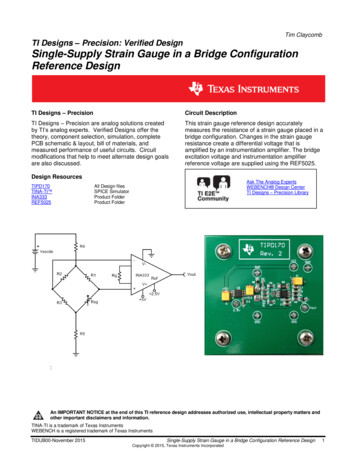
UM0727User manualIVESTEVAL-ISA018V1 demonstration board based on resonanthalf-bridge SMPS for industrial applicationsIntroductionNACTThis user manual describes a high efficiency solution for industrial power supplies with acontinuous output power of 150 W and peak power up to 240 W. It takes advantage of theresonant approach to minimize switching losses, resulting in higher than 90% efficiency. Thetopology is based on half-bridge and operated in a resonant fashion by means of a resonantLC tank, driven by the L6599 dedicated controller.-IThe board provides one regulated output, VO 24 V with IO 6 A, and an overload capabilityof up to IO 10 A. Output voltage and current are controlled by the TSM1011 constantvoltage and constant current controller, providing square output regulation, while theoverload is managed by thermal protection (PTC) on the output rectifiers.STEVAL-ISA018V1 board prototypeINACTIVE-INACTIVFigure 1.EThe board, shown in Figure 1, is obtainable using the order code STEVAL-ISA018V1.May 2010Doc ID 15906 Rev 11/18www.st.com
ContentsUM0727ContentsDemonstration board description . . . . . . . . . . . . . . . . . . . . . . . . . . . . . . 42Experimental waveforms . . . . . . . . . . . . . . . . . . . . . . . . . . . . . . . . . . . . 123EMI measurements . . . . . . . . . . . . . . . . . . . . . . . . . . . . . . . . . . . . . . . . . 154Conclusions . . . . . . . . . . . . . . . . . . . . . . . . . . . . . . . . . . . . . . . . . . . . . . . 165Revision history . . . . . . . . . . . . . . . . . . . . . . . . . . . . . . . . . . . . . . . . . . . 17INACTIVE-INACTIVE-INACTIVE12/18Doc ID 15906 Rev 1
UM0727List of figuresList of figuresFigure 8.Figure 9.Figure 10.IVEINACTIVE-INACTIVEFigure 11.Figure 12.NACTFigure 7.STEVAL-ISA018V1 board prototype . . . . . . . . . . . . . . . . . . . . . . . . . . . . . . . . . . . . . . . . . . 1Schematic . . . . . . . . . . . . . . . . . . . . . . . . . . . . . . . . . . . . . . . . . . . . . . . . . . . . . . . . . . . . . . . 5Resonant transformer: pinout . . . . . . . . . . . . . . . . . . . . . . . . . . . . . . . . . . . . . . . . . . . . . . . . 6Resonant transformer: mechanical drawing . . . . . . . . . . . . . . . . . . . . . . . . . . . . . . . . . . . . . 7STEVAL-ISA018V1 board layout with tracks . . . . . . . . . . . . . . . . . . . . . . . . . . . . . . . . . . . . 7Midpoint voltage and transformer current - Vin 230 Vac, Vout 24.6 V,Iout 2 A (CH1: HB midpoint voltage; CH2: transformer current) . . . . . . . . . . . . . . . . . . . 12Midpoint voltage and transformer current - Vin 230 Vac, Vout 24.6 V,Iout 2 A (CH1: HB midpoint voltage; CH2: transformer current) . . . . . . . . . . . . . . . . . . . 12Midpoint voltage and transformer current - Vin 230 Vac, Vout 24.6 V,Iout 2 A (CH1: HB midpoint voltage; CH2: transformer current) . . . . . . . . . . . . . . . . . . . 13Midpoint voltage and transformer current - Vin 230 Vac, Vout 24.6 V,Iout 2 A (CH1: HB midpoint voltage; CH2: transformer current) . . . . . . . . . . . . . . . . . . . 13Midpoint voltage and transformer current - Vin 230 Vac, Vout 24.6 V,Iout 2 A (CH1: HB midpoint voltage; CH2: transformer current) . . . . . . . . . . . . . . . . . . . 14Conducted emissions - phase - Vin 230 Vac, Iout 6 A . . . . . . . . . . . . . . . . . . . . . . . . . 15Conducted emissions - neutral - Vin 230 Vac, Iout 6 A . . . . . . . . . . . . . . . . . . . . . . . . 15-IFigure 1.Figure 2.Figure 3.Figure 4.Figure 5.Figure 6.Doc ID 15906 Rev 13/18
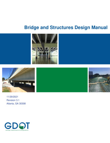
Demonstration board description1UM0727Demonstration board descriptionIVEThe STEVAL-ISA018V1 board is based on an LLC resonant converter, and employs the5 Ω, 500 V STF21NM50N power MOSFET as the primary switches in the half-bridge. TheSTF21NM50N is produced using STMicroelectronics’ proprietary high voltage MDmesh IItechnology. Thanks to this technology, the switch features a very low RDS(on) per area, lowgate charge and high switching performance. The device is available in different packages,i.e. the TO-220, TO-247 and TO-220FH.Table 1.NACTThe demonstration board has been designed based on the specifications listed in Table 1.Main specificationsParameterValueInput voltage rangea. 185 to 265 Vac - b. 85 to 185 Vac (with voltage double)Input frequency range50/60 Hz24 V 2%-IOutput voltageOutput power150 W (240Wpk)EN60950ESafetyEN55014IVEMICTThe electrical schematic of the board is shown in Figure 2. The input section is providedwith a connector for line input and a jumper for voltage double operation for a 110 Vac inputvoltage.-INAThe output voltage is available on the CN3 connector. The converter is controlled by theL6599, a double ended primary controller for resonant half-bridge ZVS (zero voltageswitching). The IC controls the output power, changing the switching frequency andcontrolling the half-bridge with a constant 50% duty cycle by means of a dedicated pin,connected to the output feedback through an optocoupler. Light load conditions aremanaged, with optimized consumption, thanks to burst mode operation. The IC alsoincludes a disable function and two-level over-current protection with programmable delay.TIVEIn order to properly run the half-bridge devices and guarantee high efficiency, the ICfeatures an internal P- channel D-MOS transistor with a typical RDS(on) of 200 mΩ as aswitching element to avoid the use of a bootstrap capacitor.INACDuring normal operation the IC is powered by the auxiliary winding of the transformer via theD9 diode. A discrete linear voltage regulator is connected in order to stabilize the auxiliaryvoltage fluctuations. The circuit consists of Q4, C42, R38, D3, D12, C32 and C33.4/18Doc ID 15906 Rev 1
/,1(&1 Doc ID 15906 Rev 1 X[ 55 5 5 X)& ' Q) Q)( 57 & & Q)& ) 17& 56 9& Q) X)& 5 N5 N' & Q) Q)& TIVE/ ' 4 ' N5 '3 Q)& 05 & .5 5 N5 N5 S)& 5& & Q) ',6 /,1( ,6(1 67% 9* 55 8 3)&B6723 *1' /9* 1 & 5 & 5 5 Q)& Q) Q)& 5 N Q)4 ' 4 E 5 5 5& 55 5 5IV5 5 5 5' 55 ' N N5 & Q)CT 9%2275 .5 N5 N/ 287 5)PLQ &) '(/ &VV X) 9& X) 9NA-I S)-03 9DF&1 9&& 4 7 ' Q)& 5 6736 6 Q& 2378 S) 6736 6' 8 5 55 5& 76 9&& & & 5 N Q& N5 & Q) N & 5 .760 95() 9FF&F 2XW&F *QG&Y &Y 8 N5 X) N5 & Q)& 5 N N& 5 5 N5 5 N .5 N5 N Q) Q)IVE5 N5 Q X) 9& N& & Q5 6 17& N& 95() QNACT& Q)& -I5 5' N5 7'. 65: (& %& 5 N2377 (50 / 3527(&7,21 5 9' 5 Q)& 5 N N& X)' &1 9 Figure 2. INACUM0727Demonstration board descriptionSchematic!- V 5/18
Demonstration board descriptionUM0727Regulation of the output voltage is performed by secondary feedback on the 24 V output.The feedback network consists of a programmable voltage reference, TSM1011, driving anoptocoupler which ensures the required insulation between the primary and secondarysections. The optotransistor drives the feedback pin (RFMIN) which controls the operation ofthe IC.IVEThe resonant transformer is based on a two-slot coil former and an EER39-PC40 ferritecore, manufactured by TDK. The transformer ensures safety insulation in accordance withEN60950.Table 2.Resonant transformer specificationsParameterValueCoreEER39 – PC40Coil former2 slot-IPrimary inductance, LpLeakage inductance, Llk450 µH 10%150 µH 10%32 (0.15x20) – 220 mΩ (DC)Secondary turns, Ns2x7 (0.2x30) (bifilar) – 40 mΩ (DC)8 (on primary winding)CTAuxiliary turns, NauxIVEPrimary turns, NpResonant transformer: pinoutTIVE-INAFigure 3.NACTIn Table 2 the main features of the transformer are listed and in Figure 3 and 4 the pinoutand the geometrical characteristics are shown respectively.INAC!- V 6/18Doc ID 15906 Rev 1
UM0727Demonstration board descriptionFigure 4.Resonant transformer: mechanical drawingNACTIVE !- V IVE-IThe output voltage can be adjusted down to 1.235 V by a voltage divider. An internaloscillator fixes the switching frequency up to 500 kHz to minimize the size of externalcomponents. The power IC features several layers of protection, such as pulse by pulsecurrent limit with internal frequency modulation aimed at an effective constant current shortcircuit protection, feedback disconnection and thermal shutdown. Finally, it can besynchronized using a dedicated pin as well as inhibited for reduced standby powerconsumption and time sequence operations.STEVAL-ISA018V1 board layout with tracksINACTIVE-INAFigure 5.CTThe board layout is shown in Figure 5. The whole power supply is produced on a doubleside 35 µm PCB FR-4 (130 x 66 mm).AM04390v1Doc ID 15906 Rev 17/18
Demonstration board descriptionTable 3.UM0727STEVAL-ISA018V1 BOM listValueDescriptionC1220 nFPolyester X2 – 275 VacC2100 nFPolyester X2 – 275 VacC3680 µFElect. capacitor 200 VC4220 pFCeramic capacitor NPOC5100 nFCeramic capacitor Y5 VC6100 nFCeramic capacitor Y5 VC74.7 nFCeramic capacitor Y5 VC810 nFCeramic capacitor Z5UC947 nFCeramic capacitor Y5 VC10100 pFCeramic capacitor NPOC12470 pFCeramic capacitor Y5 VC14470 pFCeramic capacitor Y5 VC15220 pFPolip. capacitor 630 VC1622 nFCeramic capacitor 630 VC174.7 µFC1847 nFC19100 nFC20470 µFC21470 µFC22470 µFC23470 µFC24220 nFC25100 µFC262.2 nFC2722 nFCeramic capacitor 630 VC28100 nFCeramic capacitor Y5 VC29100 nFCeramic capacitor Y5 VC30100 nFCeramic capacitor Y5 VC32100 µFElect. capacitor 25 VC33100 nFCeramic capacitor Y5 VC3547 nFCeramic capacitor Y5 VC36100 nFCeramic capacitor Y5 VC37680 µFElect. capacitor 200 VC394.7 nFCeramic capacitor Y2 – 250 VacC404.7 nFCeramic capacitor Y2 – 250 VacNACT-IEIVElect. capacitor-INACTElect. capacitor Y5 VTIVEINAC8/18IVEReferenceCeramic capacitor Y5 VElect. capacitor 35 VElect. capacitor 35 VElect. capacitor 35 VElect. capacitor 35 VCeramic capacitor Y5 VElect. capacitor 50 VPolyester capacitor Y1 - 300 VacDoc ID 15906 Rev 1
UM0727STEVAL-ISA018V1 BOM list (continued)ReferenceValueDescriptionC421 µFElect. capacitor 160 VCN13 posConnector - pitch 3.96 mmCN22 posConnector - pitch 3.96 mmCN34 posConnector - pitch 3.96 mmDP1S1M/11TRectifier 1 A - 1000 V - DO214ACNACTD1Bridge rectifier 8 A - 600 VIVETable 3.Demonstration board descriptionD2Zener diode 24 V - 1 WLS4148Ultrafast diode 200 mA - 75 V - SOD80D4LS4148Ultrafast diode 200 mA - 75 V - SOD80D5LS4148Ultrafast diode 200 mA - 75 V - SOD80D6LS4148Ultrafast diode 200 mA - 75 V - SOD80D7LS4148Ultrafast diode 200 mA - 75 V - SOD80D8STPS20H100STMicroelectronics - Schottky rectifier 2x10A - 100 VD9BAV23CFast rectifier 2x400 mA - 250 V - SOT23D11LS4148Ultrafast diode 200 mA - 75 V - SOD80IVE-ID3STPS20H100STMIcroelectronics - Schottky rectifier 2x10 A - 100 VDL1LEDLED red 0805L12x25 mHNTC12Ω-4ANTC210 kΩF13.15 AR1100 kΩR2470 kΩR310 kΩResistor, 5% - SMD 0603R410 kΩResistor, 5% - SMD 0603R51 MΩResistor, 5% - SMD 0603R656 kΩResistor, 5% - SMD 0603R810 ΩResistor, 5% - SMD 060310 ΩResistor, 5% - SMD 0603R10100 ΩResistor, 5% - SMD 0603R1110 ΩResistor, 5% - SMD 0603R12100 ΩResistor, 5% - SMD 0603R13100 ΩResistor, 5% - SMD 1206R14100 ΩResistor, 5% - SMD 0603R9CTD13TIVEZener diode 12 V - 1 WINACD12-INACM choke - TDK HF2836 - 1.2 ANTC Inrush current suppressorNTC -40 C to 125 CFuse 250 V delayedResistor, 5% - SMD 1206Resistor, 5% - SMD 1206Doc ID 15906 Rev 19/18
Demonstration board descriptionSTEVAL-ISA018V1 BOM list (continued)ValueDescriptionR1510 kΩResistor, 5% - SMD 0603R16220 ΩResistor, 5% - SMD 0603R171 kΩResistor, 5% - SMD 0603R18470 ΩResistor, 5% - SMD 0603R1910 ΩResistor, 5% - SMD 0603R201 kΩResistor, 5% - SMD 0603R2115 kΩResistor, 5% - SMD 0603R221 kΩResistor, 5% - SMD 0603R231 kΩResistor, 5% - SMD 0603R2422 kΩResistor, 5% - SMD 0603R2510 kΩResistor, 5% - SMD 0603R260.1 ΩShunt resistor 3 WR271 kΩResistor, 5% - SMD 0603R2822 kΩResistor, 1% - SMD 0603R292.2 kΩResistor, 5% - SMD 0603R304.7 kΩR3110 ΩR321 kΩR34220 kΩR35470 kΩR36100 kΩR371 kΩR384.7 kΩR40100 ΩR415.6 kΩResistor, 1% - SMD 0603R433.3 kΩResistor, 5% - SMD 0603R4522 kΩResistor, 5% - SMD 0603R461 kΩResistor, 5% - SMD 0603R4710 kΩResistor, 5% - SMD 0603R48100 kΩResistor, 5% - SMD 0603R4910 kΩResistor, 5% - SMD 0603R500ΩResistor, - SMD 0603R511 kΩResistor, 5% - 1WR52220 kΩResistor, 5% - SMD 1206R53220 kΩResistor, 5% - SMD 1206-IEIVResistor, 5% - SMD 0603CTResistor, 5% - SMD 0603Resistor, 5% - SMD 0603-INAResistor, 5% - SMD 0603TIVEINAC10/18NACTReferenceIVETable 3.UM0727Resistor, 5% - SMD 1206Resistor, 5% - SMD 1206Resistor, 5% - SMD 0603Resistor, 5% - SMD 1206Resistor, 5% - SMD 0603Doc ID 15906 Rev 1
UM0727Table 3.Demonstration board descriptionSTEVAL-ISA018V1 BOM list (continued)ValueDescriptionR540ΩResistor, - SMD 0603R5547 ΩResistor, 5% - SMD 1206T1SRW40EC2-E01Switch mode transformer - TDKU1L6599STMicroelectronics - high voltage resonant controllerU2TCET1101Optocoupler - VishayU3TS321STMicroelectronics - low power single operational amplifier - SOT 23-5U4TSM1011STMicroelectronics constant voltage and constant current controller - SO-8Q1STB21NM50NSTMicroelectronics - MOSFET MDmesh II 500 V -0.15 Ω - 18 A - D2PAKQ2STB21NM50NSTMicroelectronics - MOSFET MDmesh II 500 V -0.15 Ω - 18 A - D2PAKQ3BC817STMicroelectronics - small signal NPN transistor 50 V 1 A tronics - NPN medium power transistor140 V - 1 A SOT-223INACTIVE-INACTIVEVaristor 300 VDoc ID 15906 Rev 111/18
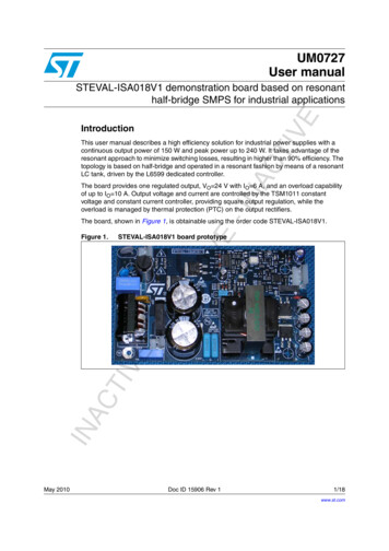
Experimental waveforms2UM0727Experimental waveformsMidpoint voltage and transformer current - Vin 230 Vac, Vout 24.6 V,Iout 2 A (CH1: HB midpoint voltage; CH2: transformer current)AM04391v1CTMidpoint voltage and transformer current - Vin 230 Vac, Vout 24.6 V,Iout 2 A (CH1: HB midpoint voltage; CH2: transformer current)INACTIVE-INAFigure 7.IVE-INACTFigure 6.IVEIn this section some experimental waveforms are given. The contents of the followingimages show the output ripple, both at low frequency and high frequency, the short circuitprotection operations and the startup and shutdown waveforms.12/18AM04392v1Doc ID 15906 Rev 1
UM0727Experimental waveformsMidpoint voltage and transformer current - Vin 230 Vac, Vout 24.6 V,Iout 2 A (CH1: HB midpoint voltage; CH2: transformer current)Midpoint voltage and transformer current - Vin 230 Vac, Vout 24.6 V,Iout 2 A (CH1: HB midpoint voltage; CH2: transformer current)AM04394v1INACTIVE-INACTIVEFigure 9.AM04393v1-INACTIVEFigure 8.Doc ID 15906 Rev 113/18
Experimental waveformsUM0727INACTIVE-INACTIVE-INACTIVEFigure 10. Midpoint voltage and transformer current - Vin 230 Vac, Vout 24.6 V,Iout 2 A (CH1: HB midpoint voltage; CH2: transformer current)14/18Doc ID 15906 Rev 1AM04395v1
UM0727EMI measurementsIVEEMI behavior has been evaluated, as shown in Figure 11 and 12, and measurements havebeen obtained using the standard settings with a 50 Ω LISN and a spectrum analyzer usingthe peak detector. The emissions are below the limit of the quasi-peak mask although thepeak detector has been used, confirming the suitability of the topology with “light” EMI filters.IVE-INACTFigure 11. Conducted emissions - phase - Vin 230 Vac, Iout 6 A!- V TIVE-INACTFigure 12. Conducted emissions - neutral - Vin 230 Vac, Iout 6 A!- V INAC3EMI measurementsDoc ID 15906 Rev 115/18
CTIVEThis document describes the STEVAL-ISA018V1 demonstration board which implements asingle output SMPS for industrial applications. The power supply is based on the L6599resonant controller and uses the latest MDmesh II power MOSFET technology in order toachieve very high efficiency in all the operating range.16/18Doc ID 15906 Rev 1
UM0727Revision historyDocument revision historyDateRevision18-May-20101ChangesInitial releaseTIVE-INACTIVE-INACTIVETable 4.INAC5Revision historyDoc ID 15906 Rev 117/18
NACTIVEUM0727Please Read Carefully:Information in this document is provided solely in connection with ST products. STMicroelectronics NV and its subsidiaries (“ST”) reserve theright to make changes, corrections, modifications or improvements, to this document, and the products and services described herein at anytime, without notice.-IAll ST products are sold pursuant to ST’s terms and conditions of sale.Purchasers are solely responsible for the choice, selection and use of the ST products and services described herein, and ST assumes noliability whatsoever relating to the choice, selection or use of the ST products and services described herein.CTIVENo license, express or implied, by estoppel or otherwise, to any intellectual property rights is granted under this document. If any part of thisdocument refers to any third party products or services it shall not be deemed a license grant by ST for the use of such third party productsor services, or any intellectual property contained therein or considered as a warranty covering the use in any manner whatsoever of suchthird party products or services or any intellectual property contained therein.NAUNLESS OTHERWISE SET FORTH IN ST’S TERMS AND CONDITIONS OF SALE ST DISCLAIMS ANY EXPRESS OR IMPLIEDWARRANTY WITH RESPECT TO THE USE AND/OR SALE OF ST PRODUCTS INCLUDING WITHOUT LIMITATION IMPLIEDWARRANTIES OF MERCHANTABILITY, FITNESS FOR A PARTICULAR PURPOSE (AND THEIR EQUIVALENTS UNDER THE LAWSOF ANY JURISDICTION), OR INFRINGEMENT OF ANY PATENT, COPYRIGHT OR OTHER INTELLECTUAL PROPERTY RIGHT.-IUNLESS EXPRESSLY APPROVED IN WRITING BY AN AUTHORIZED ST REPRESENTATIVE, ST PRODUCTS ARE NOTRECOMMENDED, AUTHORIZED OR WARRANTED FOR USE IN MILITARY, AIR CRAFT, SPACE, LIFE SAVING, OR LIFE SUSTAININGAPPLICATIONS, NOR IN PRODUCTS OR SYSTEMS WHERE FAILURE OR MALFUNCTION MAY RESULT IN PERSONAL INJURY,DEATH, OR SEVERE PROPERTY OR ENVIRONMENTAL DAMAGE. ST PRODUCTS WHICH ARE NOT SPECIFIED AS "AUTOMOTIVEGRADE" MAY ONLY BE USED IN AUTOMOTIVE APPLICATIONS AT USER’S OWN RISK.TIVEResale of ST products with provisions different from the statements and/or technical features set forth in this document shall immediately voidany warranty granted by ST for the ST product or service described herein and shall not create or extend in any manner whatsoever, anyliability of ST.ST and the ST logo are trademarks or registered trademarks of ST in various countries.Information in this document supersedes and replaces all information previously supplied.INACThe ST logo is a registered trademark of STMicroelectronics. All other names are the property of their respective owners. 2010 STMicroelectronics - All rights reservedSTMicroelectronics group of companiesAustralia - Belgium - Brazil - Canada - China - Czech Republic - Finland - France - Germany - Hong Kong - India - Israel - Italy - Japan Malaysia - Malta - Morocco - Philippines - Singapore - Spain - Sweden - Switzerland - United Kingdom - United States of Americawww.st.com18/18Doc ID 15906 Rev 1
UM0727 Demonstration board description Doc ID 15906 Rev 1 7/18 Figure 4. Resonant transformer: mechanical drawing