Transcription
EPA-744-S-05-001August 2005Solders in Electronics:A Life-Cycle AssessmentSummaryThis summary document is based on information presented in the project report,Solders in Electronics: A Life-Cycle Assessment, written by the University ofTennessee under a grant from EPA. Some information in the Life Cycle Assess ment was provided by individual technology vendors and has not been indepen dently corroborated by EPA. The identification of specific products or processes inthis document is not intended to represent an endorsement by EPA or the U.S.Government. This summary document has not been through a formal externalpeer review process.
AcknowledgmentsThis document was prepared for the U.S. Environmental Protection Agency’s Design for theEnvironment (DfE) Lead-Free Solder Project by Abt Associates under contract #68-W-01 039. This document is based primarily on the full project report, Solders in Electronics: ALife-Cycle Assessment, prepared by Jack R. Geibig and Maria Leet Socolof of the University ofTennessee Center for Clean Products and Clean Technologies under joint funding from theU.S. Environmental Protection Agency’s Design for the Environment Program in the Eco nomics, Exposure, and Technology Division (EETD) of the Office of Pollution Preventionand Toxics (OPPT), and through financial contributions from the following organizations:Agilent Technologies, Cookson-Fry, Delphi-Delco, Hewlett Packard, Intel, InternationalBusiness Machines (IBM), Sematech, Pitney Bowes, Rockwell Collins, and Thomson Con sumer Media.The Life-Cycle Assessment would not have been possible without the assistance of thetechnology suppliers and their customers who voluntarily participated in the project. Theproject Core Group provided valuable guidance and feedback throughout the preparation ofthe report. Core Group members include the Core Group Co-Chairs Kathy Hart, ProjectLead, U.S. EPA OPPT, DfE Branch; Holly Evans, formerly of Electronic Industries Alliance;Fern Abrams, IPC; and the Core Group Members Todd Brady, Intel Corp.; Maria Socolofand Jack Geibig, University of Tennessee Center for Clean Products and Clean Technologies;Anne Brinkley, IBM; Lee Vroom, Thomson Consumer Electronics; Mark Corbett, PitneyBowes; Walter Worth, International Sematech; Pete Palmer, Cookson-Fry; Jerry Gleason,Hewlett Packard; and Brenda Baney, Delphi-Delco.
ContentsIntroduction. 1Question 1:What is a life-cycle assessment? . 3Question 2:Which solders were investigated during the project? . 5Question 3:How were life-cycle environmental and healthimpacts evaluated? . 6Question 4:How do the environmental and health impacts compareamong paste solders? . 9Question 5:How do the environmental and health impacts compareamong bar solders? . 16Question 6:What are the limitations of the study? . 23Question 7:What can electronics manufacturers do to reduceenvironmental and health impacts? . 27Question 8:What are the challenges to implementinglead-free soldering? . 31Question 9:What are the performance differences among the solders? . 36Question 10:What are the potential market impacts of a switchto lead-free solders? . 42
IntroductionThis report summarizes the results of an analysis conducted by the University of Tennessee’s(UT) Center for Clean Products and Clean Technologies for the U.S. Environmental Protec tion Agency’s Design for the Environment (DfE) Lead-Free Solder Partnership (LFSP). TheDfE LFSP is a voluntary, cooperative partnership among the DfE Program, UT, the IPC–Association Connecting Electronics Industries (IPC), the Electronic Industries Alliance(EIA), several individual electronics companies, and other interested parties. The partnershipassessed the environmental life-cycle impacts of selected lead-free solders as alternatives totin-lead solder. The DfE LFSP analysis also provides an assessment of the recyclability andleachability of the solders.PURPOSEAND SCOPE OF THE STUDYThe purpose of the lead-free solder study is threefold:1. to evaluate the life-cycle environmental impacts of selected lead-based and lead-freesolder alternatives using life-cycle assessment (LCA)2. to evaluate the effects of lead-free solders on leachability, recycling, and reclamation atthe end-of-life3. to identify data gaps or other potential areas of analysis for future investigation by EPAor industryThis study used LCA to evaluate both lead-based and lead-free solder alternatives. LCAs,which are generally global and non-site specific in scope, look at the full life cycle of theproduct being evaluated, from materials acquisition to manufacturing, use, and end-of-life(i.e., final disposition). The LFSP LCA considers impacts related to material consumption,energy use, air resources, water resources, landfills, human toxicity, and ecological toxicity, aswell as leachability and recycling.NEEDFOR THE STUDYEutectic tin-lead (SnPb) solder has long been the primary choice for assembling electronicsdue to its reflow properties, low melting point, and the relative ductility of the solder jointsformed; however, concern over lead’s relatively high toxicity to human health and the envi ronment and ensuing international market and legislative pressures have led the U.S. elec tronics industry to begin switching to lead-free solders. Although the performance of themetals and fluxes of many of the alternatives has been studied, their life-cycle environmentalimpacts have not yet been evaluated. The LFSP offers the opportunity to mitigate currentand future risks by helping the electronics industry to identify lead-free solders that are lesstoxic and that pose the fewest risks over their life cycles. The LFSP study also allows theelectronics industry to make environmentally informed choices when assessing and imple menting improvements, such as changes in product, process, and activity design, raw mate rial use, industrial processing, consumer use, and waste management. Additionally, manyother organizations and individuals in the U.S. and abroad have expressed interest in obtain ing objective, detailed information about the life-cycle impacts of selected lead-free solders.About EPA’s Design for theEnvironment ProgramEPA’s Office of PollutionPrevention and Toxicsestablished the DfE Program in1992 to encourage businessesto incorporate environmentalconcerns into their businessdecisions. DfE industry projectsare cooperative, joint partner ships with trade associations,businesses, public-interestgroups, and academia to assistbusinesses in specific industriesto identify and evaluate moreenvironmentally soundproducts, processes, andtechnologies. The DfE LeadFree Solder Partnershipconsisted of members ofelectronics industry tradeassociations, circuit boardassemblers, solder suppliers,academic institutions, andEPA. The direction and focusof this project was determinedby the project partners.1
Approximately 176 million pounds of lead-based solder were used world-wide in 2002.Electronics in the U.S. is a 400 billion-per-year industry facing significant legislative andmarket pressures to phase out the use of lead-based solder and switch to lead-free alterna tives. The European Restriction of Hazardous Substances in Electrical and ElectronicEquipment (RoHS) Directive (2002/95/EC) stipulates that lead and other selected toxicchemicals in electrical and electronic equipment be replaced by July 2006. In Japan, subse quent to take back (recycling) legislation that took effect in that country in 2001, theJapanese Ministry of the Environment and the Ministry of Economy, Trade and Industrysuggested a voluntary phase-out of lead, along with increased end-of-life (EOL) productrecycling. Consumer demand for lead-free products may also increase as the general publicbecomes more aware of lead issues. All of these forces combine to drive the U.S. electronicsmarket inexorably toward lead-free solders. Managing the environmental impacts posed bythis change is crucial to the long-term environmental sustainability of both the U.S. andglobal electronics industries. Using this evaluation, the U.S. electronics industry will bebetter prepared to meet the growing demand for extended product responsibility, to helpguide public policy towards informed, scientifically-based solutions that are environmentallypreferable, and be better able to meet the competitive challenges of the world market. Inaddition, the LCA model and associated results provide a baseline upon which solder alterna tives not included in the study can potentially be evaluated. This will allow for furtherexpedited LCA studies.This booklet summarizes the key findings of the DfE Lead-Free Solder Partnership study.The information is presented in ten sections that summarize the following: the study’s life-cycle assessment methodology; the environmental and health impacts of the solders evaluated; the limitations of the study and alternative data analyses; steps circuit board manufacturers can take to reduce environmental and healthimpacts; challenges to implementing lead-free soldering; and information on cost and performance differences among the solder.For more detailed information on any of these topics, the reader is encouraged to referencethe full project report, Lead-Free Solders: A Life-Cycle Assessment (Geibig and Socolof, 2005).The document may be viewed at www.epa.gov/dfe.2
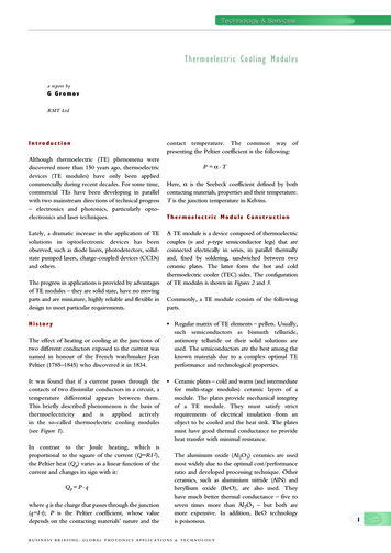
Question 1:What is a life-cycle assessment?The DfE Lead-Free Solder Partnership (LFSP) conducted this analysis of selected lead-basedand lead-free solder alternatives using a life-cycle assessment (LCA) approach, which allowedfor a comprehensive analysis of the environmental consequences of a product system over itsentire life. LCA, which is increasingly being used by industry, contains four major steps asdefined by the Society of Environmental Toxicology and Chemistry (SETAC) and morerecently by the International Standards Organization (ISO):1. Goal Definition and Scoping lays out the rationalization for conducting the LCA andits general intent, as well as specifying the product systems and data categories to bestudied.2. Life-Cycle Inventory (LCI) involves the quantification of raw material and fuel inputs,and solid, liquid, and gaseous emissions and effluents.3. Life-Cycle Impact Assessment (LCIA) characterizes the environmental burdensidentified in the LCI and assesses their effects on human and ecological health, as wellas other abiotic effects, such as smog formation and global warming.4. Improvement Assessment or Interpretation of Results uses findings from the analysisto identify and evaluate opportunities for reducing life-cycle environmental impacts ofa product, process, or activity, or to reach conclusions and provide recommendations.SETAC’s definition includes the improvement assessment component, whereas ISOincludes the life-cycle interpretation component. The LFSP LCA did not perform thisstep; it is left to the electronics industry and others to complete this step for theirspecific operation or interests using the results of this study.LCA evaluates the life-cycle environmental impacts from each of five major life-cycle stages:raw materials extraction/acquisition, materials processing, product manufacture, product use,and final disposition/end-of-life. Figure 1.1 briefly describes each of these stages for a solderproduct system. The resource flows (e.g., material and energy inputs) and the emissions,waste, and product flows (e.g., outputs) within each life-cycle stage, as well as the interactionbetween each stage (e.g., transportation) are evaluated to determine the environmentalimpacts. The LFSP LCA combines raw materials extraction and materials processing into one“upstream” life-cycle stage in the presentation of results.3
Figure 1.1. Life-Cycle Stages for Solder Alternatives4
Question 2:Which solders were investigatedduring the project?Both paste and bar solders were evaluated in this study. Paste solders are screened ontoprinted wiring boards (PWBs) to facilitate placement of components, then reflowed bypassing the PWB assembly though a high-temperature oven. Reflow soldering is used toattach surface mount components and other micro-componentry to a circuit board duringassembly. Bar solders are melted in a solder pot and then pumped through a nozzle thatforms a defined wave over which the assembly is passed. Wave soldering is used to attachlarge surface devices and feed-through components. Wave soldering is used mostly in lowtech, low-cost applications, and reflow soldering is usually used for higher-tech applications.Table 2.1 lists the specific solders that were investigated in this study.Table 2.1. Solders Selected for EvaluationThe project participants chose the individual solders based on a variety of factors, such ascurrent market trends and solder performance studies; all of the solders are currently avail able for use in the electronics industry. Eutectic tin/lead (SnPb) solder, the only lead-basedsolder that was evaluated, was chosen as the baseline for both wave and reflow applications.Tin/copper (SnCu) was selected because it is currently being used by segments of theindustry as a low-cost substitute for SnPb in wave solder applications. Tin/silver/copper(SAC) was selected because of its ability to function in both a wave solder and reflow envi ronment and because it appears to be emerging, through testing, as a top choice for asubstitute for SnPb (NEMI, 2002). The evaluation group also includes two bismuthcontaining solders—bismuth/tin/silver (BSA) and tin/silver/bismuth/copper (SABC)—inorder to assess their environmental impacts, particularly at the end-of-life, because they arebeing considered by the industry partners as possible replacements for lead-based solder.FUNCTIONAL UNITIn an LCA, product systems are evaluated on a functionally equivalent basis. The “functionalunit” normalizes data based on equivalent use to provide a reference for relating processinputs and outputs to the inventory and impact assessment across alternatives.For this project, the functional unit is a unit volume of solder required to form a viablesurface mount or through-hole connection between the PWB and the component. Thefunctional unit is based on the understanding that a similar volume of solder is required tofill the space in a solder joint regardless of the type of solder used. Thus, a volume of onethousand cubic centimeters of solder was selected for use as the functional unit in the LCA.5
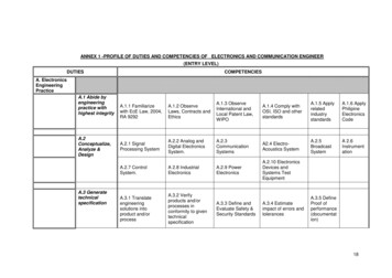
QUESTION 3:How were life-cycle environmentaland health impacts evaluated?Two of the phases of an LCA, life-cycle inventory and life-cycle impact assessment, arenecessary to calculate environmental impacts.LIFE-CYCLE INVENTORYLife-cycle inventory (LCI) involves identifying and quantifying material and resource inputs,and emission and product outputs, from the product being evaluated. For the LFSP, LCIinputs include materials, energy, and other resources used throughout the life cycle of thesolders. Outputs include products, air emissions, water effluents, and releases to land.Figure 3.1 shows the processes that are included in the scope of the LFSP for the SnPb pastesolder life cycle. Although the process diagrams for solder alternatives may vary somewhatfrom solder to solder and from paste to bar, the scope for each alternative is similar to thatshown for the SnPb paste solder, except for the following differences:1. The upstream production of lead is replaced with the appropriate alternate metalsfound in each alloy.2. In addition to the fuels used in paste manufacturing (i.e., natural gas, heavy fuel oil),liquefied petroleum gas (LPG) is also used as a fuel input in bar manufacturing.3. The cost of copper smelting for the BSA alloy is potentially prohibitive because of itshigh bismuth content. Therefore, flows from demanufacturing are assumed to be sentto a landfill or an incinerator rather than to a copper smelter.Figure 3.1. SnPb Paste Solder Life-Cycle Processes6
Given the enormous amount of data involved in inventorying all of these inputs and outputs,decision rules were used to determine what to include in the LCI. Decision rules are de signed to make data collection manageable, but still representative of the product and itsimpacts. For example, upstream process inputs in major processes that meet one or more ofthe following criteria would be included in this study: constitutes greater than one percent of the total mass or energy required to manufac ture the solder; materials falling into the one to five percent range were evaluated based on the otherdecision rule criteria, as well as the availability of data; is known or suspected to have environmental significance; is known or suspected to have significant energy requirements; is physically unique to a solder alternative over the baseline SnPb solder; or is functionally significant to the solder.The data collected for this study included primary data that were obtained for this project,data obtained through site visits, and testing or secondary data that were obtained fromexisting databases. LCI data were imported into GaBi, a publicly available life-cycle assess ment tool in which customized life-cycle process profiles were developed for each of thesolders.LIFE-CYCLE IMPACT ASSESSMENTLife-cycle impact assessment (LCIA) is the process by which the environmental burdensidentified in the LCI are translated into environmental impacts. It is important to note thatdirect comparisons cannot be made across impact categories, because impacts in differentimpact categories are generally calculated based on different scales. The LFSP LCIA con sisted of two steps: classification and characterization.CLASSIFICATIONThe LCIA methodology employed in this study places each impact and output from the LCIinto one or more of sixteen impact categories, including global warming, stratospheric ozonedepletion, photochemical smog, energy consumption, potential chronic human health, andaquatic ecotoxicity.CHARACTERIZATIONThe characterization step of LCIA converts and aggregates LCI results to common unitswithin an impact category to produce an impact score. Three different approaches are usedto quantify the magnitude of potential impacts, depending on the impact category: Loading: An impact score is based on the inventory amount (e.g., resource use). Equivalency: An impact score is based on the inventory amount weighed by a certaineffect, equivalent to a reference chemical [e.g., global warming impacts relative tocarbon dioxide (CO2)].7
Scoring of inherent properties: An impact score is based on the inventory amountweighted by a score representing a certain effect for a specific material (e.g., toxicityimpacts are weighted using a toxicity scoring method).Table 3.1 presents the 16 impact categories and a description of how each is calculated.Table 3.1. Impact CategoriesaAcronyms: Particulate matter with average aerodynamic diameter less than 10 micrometers (PM10); totalsuspended particulates (TSP); biological oxygen demand (BOD); total suspended solids (TSS).8
Question 4:How do the environmental andhealth impacts compare amongpaste solders?This section compares the results for each impact category described in Question 3 for thepaste solders. Although some LCAs assign importance ranks or weights to impact categories,this LCA does not include this step because it requires subjective choices that might not beappropriate for all stakeholders.WHICH SOLDER SCORED HIGHESTEACH IMPACT CATEGORY?ANDLOWESTINTable 4.1 presents the life-cycle impact scores for each of the paste solders evaluated and aquality rating given to each impact category score. Highlights from the results are as follows: Among all of the solders,– SnPb has the highest impact category score (shown in bold) for six impactcategories;– SAC has the highest impact category score in ten impact categories;– SnPb has the lowest impact category score (shaded values) in five impact categories;and– BSA has the lowest impact category score in seven impact categories.Table 4.1. Paste Solder Life-Cycle Impact ScoresaThe functional unit is 1,000 cc of solder applied to a printed wiring board.Quality summarizes the overall relative data quality associated with each impact category: high (H), medium(M), or low (L).Note: Bold indicates the solder with the highest impact score within an impact category; shaded scores indicatethe solder with the lowest impact score.b9
Among the lead-free solders,– BSA has the lowest impact score in all categories except non-renewable resource use;– SAC has the highest impact score in all categories except aquatic ecotoxicity andoccupational cancer; and– SABC has the highest impact score in occupational cancer and aquatic ecotoxicity,and the lowest impact score in non-renewable resource use.Note that these impact scores only indicate the relative or incremental differences among thesolders and do not necessarily indicate any particular level of concern.Figure 4.1 displays the relative differences of the 16 environmental and human health impactcategories presented in Table 4.1. The values derived for the figure are the log of the ratio ofthe alternative solder impact score to that of the SnPb baseline solder score for each impactcategory. Log ratios reported as a positive number reflect a favorable comparison (lesserrelative impacts) to the baseline SnPb solder for the alternative; a negative number representsan unfavorable result (greater relative impacts) as compared to the baseline solder. Note thatcomparisons should only be made within not across impact categories.Figure 4.1. Relative Comparison of Paste Solder Life-Cycle Impact ScoresNote: Do not compare across impact categories.10
WHICH LIFE-CYCLE STAGES DRIVETHE IMPACT SCORES?A summary of the top contributing life-cycle stages for each solder by impact category ispresented in Table 4.2. The life-cycle stage or stages that contribute 50 percent or more toimpacts in each impact category are listed in the table. In cases where an individual lifecycle stage did not constitute a majority, the top stages that together exceed 50 percent arelisted; the life-cycle stage with the greatest contribution is listed first. The use/applicationlife-cycle stage dominates many of the solder impacts. For SnPb, the use/application stage contributes the majority of the impacts for thirteenout of sixteen impact categories. Nearly all of the impacts associated with the use/application stage result from the generation of the energy consumed during the solderreflow process during PWB assembly. SAC has nine impact categories where the use/application stage is a major contributorand six categories in which the upstream stage provides the majority of impacts. Theupstream impacts are primarily from silver production. EOL and manufacturing aretop contributors to the occupational non-cancer impact category only. The BSA impacts are driven by the use/application stage in eleven categories, by theupstream stage in three categories, and by EOL in two categories. The impact categories for SABC are driven by the same life-cycle stages as BSA withthe exception of the occupational non-cancer impact category, which is driven by theEOL and manufacturing stages, as is the case for SnPb and SAC.Table 4.2. Paste Solder Life-Cycle Stages Contributing aMajority to Each Life-Cycle ImpactNATURAL RESOURCE IMPACTSNon-renewable resource use. Non-renewable natural resources are typically abiotic materi als, such as mineral ore or fossil fuels. The use/application stage contributes 65 to 96percent of the non-renewable natural resource use impact category depending on the solder.Electricity generation in the reflow application process is the main driver for this impact11
category. SnPb consumes the most electricity per functional unit due to its higher relativedensity (see Table 2.1). BSA consumes less energy during reflow application relative to theother paste solders, because of its lower melting temperature (despite its high density). SACand SABC have greater overall impacts for this category due to the significant contribution ofupstream silver production.Renewable resource use. Renewable resources are typically biotic materials, such as forest oranimal products, plants, and water. Impacts from the use/application stage contribute 93 to99 percent of the total renewable resource use category and are due primarily to the con sumption of water for electricity generation in the reflow application process. SnPb has thehighest impact score in this category, because it consumes the most electricity per functionalunit due to its higher relative density (see Table 2.1). BSA has the lowest impact categoryscore, because it consumes less electricity during reflow application relative to the other pastesolders due to its lower melting temperature (despite its high density).Energy use. Energy use impact scores are the sum of electrical and fuel energy inputs.Electricity use in the reflow application process is the main driver for this impact category.SAC has the highest impact score due to the energy used during silver extraction and pro cessing. The energy impacts from silver processing approach those of tin processing, eventhough the silver content (3.9%) of SAC is considerably less than the tin content (95.5%).BSA’s energy use score is lower relative to the other paste solders because of its lower meltingtemperature (see Table 2.1).Landfill space use. Landfill space use impacts are calculated based on the volume of landfillspace consumed by solid, hazardous, and/or radioactive waste. SnPb has the lowest score forthis impact category; SAC has the highest score. Silver production, specifically the genera tion of slag, is responsible for the upstream life-cycle stage dominating this impact categoryfor the lead-free solders. For example, the upstream life-cycle stage accounts for 67 to 84percent of the total landfill space impact score for the lead-free solders. In contrast, theupstream stage accounts for less than 1.4 percent of the total SnPb landfill space impactscore, which is driven by the use/application stage.ABIOTIC ECOSYSTEM IMPACTSGlobal warming. The impact scores for the effects of global warming and climate change arecalculated using the mass of a global warming gas released to air modified by a globalwarming potential equivalency factor. Global warming impacts follow the trend observed forthe energy use category (i.e., the use/application stage drives this impact category), which isexpected given that electricity generation produces significant amounts of carbon dioxide, aglobal warming gas. BSA has a substantially lower score in this category because it has alower melting temperature, which reduces its energy consumption during reflow application.SAC has the highest score in this category due to the higher global warming scores forupstream silver extraction and processing relative to the other metals.12
Stratospheric ozone depletion. Ozone depletion impact scores are based on the identity andamount of ozone depleting chemicals that are released to air. SAC has the highest score forthis impact category, whereas BSA’s score is the lowest. The use/application phase dominatesthe impacts for all of the solders, although the upstream stage contributes a larger portion ofthe total impacts for the lead-free alternatives than for SnPb. Electricity consumption in thesolder reflow process is entirely responsible for ozone depletion impacts in the use/applica tion phase. Silver production is the top contributor to the upstream life-cycle stage for thenon-lead alternatives. It should be noted that some of the materials in the ozone depletioninventory should have been phased out and might have been (the inventory is just dated).An alternate analysis that was performed with only the non-phased out ozone depletingchemicals in the inventory showed similar differences between the solders; however, themanufacturing stage now dominates for all of the solders.Photochemical smog. Photochemical smog refers to the release of chemicals that may reactwith sunlight in the atmosphere to produce photochemical oxidants, such as troposphericozone. Upstream and use/application stages both contribute significantly to the photo chemical smog impact category for the lead-free solders, whereas the use/application stagecontributes nearly 93 percent of the SnPb smog impacts. The solder reflow applicationprocess is the only contributor to the use/application stage, whereas silver production is themain contributor to the upstream stage.Acidification. Acidification impacts refer to the release of chemicals that may contribute tothe formation of acid precipitation. SAC has the highest impact score for this category; SnPbhas the lowest score. Approximately 93 percent of the SnPb life-cycle acidification impactsare driven by the use/application stage. The lead-free solder impacts are driven by both theupstream and use/application stages. Electricity generation is the largest contributor to theuse/application phase, whereas silver production drives the upstream contribution. Sulfurdioxide and nitrogen oxides are the main contributors of the acidification impacts.Air particulates. Air particulate impacts are based on the amount of particulate matter withan average aerodynamic diameter less than 10 micrometers (PM10) that is released to the air.Total suspended particulates/dust wa
Association Connecting Electronics Industries (IPC), the Electronic Industries Alliance (EIA), several individual electronics companies, and other interested parties. The partnership assessed the environmental life-cycle impacts of selected lead-free solders as alternatives to


![History of Electronics electricity [Read-Only]](/img/18/history-20of-20electronics-20-20electricity.jpg)