Transcription
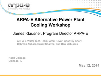
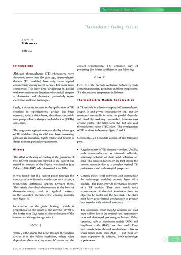
Technology & ServicesThermoelectric Cooling Modulesa report byG GromovRMT LtdIntroductionAlthough thermoelectric (TE) phenomena werediscovered more than 150 years ago, thermoelectricdevices (TE modules) have only been appliedcommercially during recent decades. For some time,commercial TEs have been developing in parallelwith two mainstream directions of technical progress– electronics and photonics, particularly optoelectronics and laser techniques.Lately, a dramatic increase in the application of TEsolutions in optoelectronic devices has beenobserved, such as diode lasers, photodetectors, solidstate pumped lasers, charge-coupled devices (CCDs)and others.The progress in applications is provided by advantagesof TE modules – they are solid state, have no movingparts and are miniature, highly reliable and flexible indesign to meet particular requirements.HistoryThe effect of heating or cooling at the junctions oftwo different conductors exposed to the current wasnamed in honour of the French watchmaker JeanPeltier (1785–1845) who discovered it in 1834.It was found that if a current passes through thecontacts of two dissimilar conductors in a circuit, atemperature differential appears between them.This briefly described phenomenon is the basis ofthermoelectricity and is applied activelyin the so-called thermoelectric cooling modules(see Figure 1).In contrast to the Joule heating, which isproportional to the square of the current (Q RI 2),the Peltier heat (Q p) varies as a linear function of thecurrent and changes its sign with it:Q p P . qwhere q is the charge that passes through the junction(q I·t); P is the Peltier coefficient, whose valuedepends on the contacting materials’ nature and thecontact temperature. The common way ofpresenting the Peltier coefficient is the following:P α.THere, α is the Seebeck coefficient defined by bothcontacting materials, properties and their temperature.T is the junction temperature in Kelvins.Thermoelectric Module ConstructionA TE module is a device composed of thermoelectriccouples (n and p-type semiconductor legs) that areconnected electrically in series, in parallel thermallyand, fixed by soldering, sandwiched between twoceramic plates. The latter form the hot and coldthermoelectric cooler (TEC) sides. The configurationof TE modules is shown in Figures 2 and 3.Commonly, a TE module consists of the followingparts. Regular matrix of TE elements – pellets. Usually,such semiconductors as bismuth telluride,antimony telluride or their solid solutions areused. The semiconductors are the best among theknown materials due to a complex optimal TEperformance and technological properties. Ceramic plates – cold and warm (and intermediatefor multi-stage modules) ceramic layers of amodule. The plates provide mechanical integrityof a TE module. They must satisfy strictrequirements of electrical insulation from anobject to be cooled and the heat sink. The platesmust have good thermal conductance to provideheat transfer with minimal resistance.The aluminum oxide (Al2O3) ceramics are usedmost widely due to the optimal cost/performanceratio and developed processing technique. Otherceramics, such as aluminium nitride (AlN) andberyllium oxide (BeO), are also used. Theyhave much better thermal conductance – five toseven times more than Al2O3 – but both aremore expensive. In addition, BeO technologyis poisonous.BUSINESS BRIEFING: GLOBAL PHOTONICS APPLICATIONS & TECHNOLOGY1
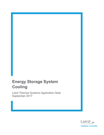
Technology & ServicesFigure 1: Simplified Scheme of TE Module and the Temperature DifferentialAlong It Electric conductors provide serial electriccontacting of pellets with each other and contactsto leading wires. For most of the low-powermodules, the conductors are made as thin films(mutilayer structure containing copper (Cu) as aconductor) deposited onto ceramic plates. Forhigh-power modules, they are made from Cu tabsto reduce resistance. Solders provide assembling of the TE module.The solders used include antimony-tin and lid-tinalloys. The solders must provide good assemblingof the TE module. The melting point of a solderis the limiting factor of operation temperature ofthe module. For long lifetime module, operationtemperature must be lower than the solder’smelting point as much as possible. Leading wires are connected to the endingconductors and deliver power from a directcurrent (DC) electrical source.Figure 2: Single-stage Module ConstructionA single-stage module consists of one matrix of pelletsand a pair of cold and warm sides (see Figure 2). Amulti-stage module can be viewed as two (see Figure 3)or more single stages stacked on top of each other.1The construction of a multi-stage module is usually ofa pyramidal type – each lower stage is bigger than theupper stage. Once the top stage is used for cooling,the lower stage requires greater cooling capacity topump heat that is dissipated from the upper stage.PerformanceFigure 3: Two-stage Module ConstructionTE modules can be characterised by maximalperformance parameters with a hot junctiontemperature (T1). Usually, they are listed in standardspecifications of a module: Tmax – maximal temperature difference along themodule at no heat load Q 0Qmax – the cooling capacity corresponding to Tmax 0Imax– the device current at TmaxUmax – the terminal voltage for Imax with no heatloadAll of the performance parameters are in aninterdependent relationship with each other.The correct analysis of a TEC operation in the realapplication could be carried out using performanceplots, which are the results of the interdependencebetween them.21. L I Anatychuk, Thermoelements and Thermoelectrical Devices, p.151, Kiev, 1979.BUSINESS BRIEFING: GLOBAL PHOTONICS APPLICATIONS & TECHNOLOGY
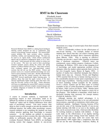
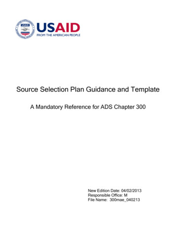
Thermoelectric Cooling ModulesFigure 4: Example of Maximum Performance PlotsMaximum Performance PlotsThe basic performance plots indicate the interdependent relationship between Imax, Umax, Qmax and Tmax. The typical examples are shown in Figure 4.Optimal Performance Plotsα2Z kRThe parameter Z is usually referred to as figure-of–3–1merit. The typical value of Z is 2.5 to 3.0 10 K .The known value of Z allows estimating of Tmaxof a single-stage TEC by the simple formula:12 Tmax 2 Z .T0They are characteristics of TEC operation in themaximum coefficient of performance2 (COP) mode.The COP is defined as cooling capacity Q divided bythe consumed electric power. Typical examples areshown in Figure 5.where T0 is the sold side temperature. The typicaltemperature dependence of Z and Tmax vs Z isshown in Figure 6.Figure-of-meritReliabilityThere are more performance parameters that areusually not presented in standard specifications ofcommercial TE modules, but that play an importantrole in a module characterisation.Commercial TE modules provide long operationlifetime in the range of 100,000 to 200,000 hours. Itis the result of a highly developed technology ofmanufacturing and high-quality raw materials. Inmany applications, TEC is a critical componentbecause it affects the temperature of the whole deviceand can have an influence on its correct operation, aswell as an impact on heat dissipation. That is whysevere reliability test procedures3 are required.These parameters are the properties of pelletmaterial (thermal conductance (k), electricalresistance (R) and the Seebeck coefficient)combined1,2 as follows:2. A L Vayner, Thermoelectric Coolers, Moscow, 1983, pp. 30–35.3. L G Stokholm, “Reliability of thermoelectric cooling systems”, Proceedings of Xth International Conference onThermoelectrics, Cardiff, UK, 1991, p. 228.BUSINESS BRIEFING: GLOBAL PHOTONICS APPLICATIONS & TECHNOLOGY3
Technology & ServicesFigure 5: Example of Optimal Performance PlotsReliability Test StandardsFor these purposes, there are many national andinternational test standards. They are unified fora range of electronic and optoelectronic devicequalifications. In the international market, Bellcorestandards are the most common, namely,GP–468–CORE (Reliability Assurance forOptoelectronic Devices).The minimal standard set of the test methods is: thethethethethemechanical shock test;vibration test;shear force test;high-temperature storage test; andtemperature cycle endurance test.Failure CriteriaThe suggested failure criteria that are in practice forreliability tests are the following: a drop in TEC maximum cooling capacity Tmaxof below its specified rating; and an increase in TEC resistance, usually of 5%or higher.4Controlling both the criteria is achievable in themethod of Z-metering 4, which is fast and quiteaccurate, realised by the test device Z-Meter. Thelatter provides the measurement of the figure-ofmerit Z and therefore the Tmax and alternatingcurrent resistance (AC R) measurement.Parameters Z and AC R are extremely sensitive tothe TEC quality and to any failure. Any slightchanges in a module – destruction of pellets,junctions, ceramics and so on – immediately result inthe noticeable change of Z (decrease) and AC R(raise) against initial fixed values.Selection of TE Module foran ApplicationEvery specific application where a TE module isrequired is characterised by a set of operationparameters and restrictions, which dictate thenecessity of accurate selection of the optimal TECtype among a wide range of single and multi-stageTECs. These parameters are: T – operating temperature difference (at knownambient Ta/hot junction Th temperatures); Q – operating cooling capacity;4. H H Woodbury, L M Levinson and R S Lewandowski, “Z-Meters”, CRC Handbook of Thermoelectrics, CRCPress, Inc., 1995, pp. 181–189.BUSINESS BRIEFING: GLOBAL PHOTONICS APPLICATIONS & TECHNOLOGY
Thermoelectric Cooling Modules I– applied or available current;modelling of a concrete TE module behaviour inparticular operating conditions. U – terminal voltage; and dimensional restrictions and others.A user can make a rough but fast estimation ofoperating temperature difference and coolingcapacity as:Q TQ Qmax (1 – Tmax ) and T Tmax (1 – Q )maxA detailed analysis must be carried out with the helpof performance plots.In Table 1, a list of typical commercial TE modulesis shown. A user can find that, concerning therequired temperature difference, the single-stageTE modules provide Tmax in a range of 65K to72K, and two and more stage types can give more(see Figure 7).Examples of such software are now advised, forexample, by the firms Melcor, Kryotherm and RMT.Application TipsIn practice, the performance and operational lifetimeof TE modules depends considerably on many factorsas follows.MountingMounting is the first procedure before any applicationof a TE module (see Figure 8). The mounting methodand applied materials must provide good thermalFigure 6: T max as a Function of Figure-of-merit ZAmong each group (single and multi-stage types),there are modules with different cooling capacity Q.When more power is required, the biggerdimensions of the TE module can provide thenecessary heat pump.If also considering the usual restrictions in the powersupply, the correct selection can become rather acomplicated task.In order to accelerate and optimise this procedure,most of the suppliers advise a kind of assistance. Inaddition, some of them advise users about softwarethat allows them to search among TECs and decideon the optimal choice using computer databaseanalysis of existing TE module types with detailedFigure 7: Maximum Performance Parameters of Commercial TE Modules of RMT5BUSINESS BRIEFING: GLOBAL PHOTONICS APPLICATIONS & TECHNOLOGY
Technology & Servicescontacts and minimum heat resistance.Figure 8: TE Module Mounted onto TO8 Header Mechanical mounting – the TE module is placedbetween two heat exchangers. This sandwich isfixed by screws or in another mechanical way.The advantage of fixing by screws lies in thepossibility to make a fast and easy disassembling ifrequired. It is suitable for large modules, forexample, with external surfaces measuring 30 x30mm or more. Miniature types require differentassembling methods.6Table 1: Typical Commercial TE modules (of RMT Ltd)Model Tmax ,K Qmax ,W Imax ,A Umax ,VSingle Stage1MT 03-004-13 670.100.400.451MT 03-008-13 670.190.400.901MT 03-012-13 670.290.401.351MC 04-004-05 680.441.600.501MC 04-018-15 680.530.402.201MC 04-032-15 680.940.404.001MT 04-128-12 656.200.8014.501MT 05-004-13 670.261.100.451MT 05-008-13 670.521.100.901MT 05-032-13 672.101.103.601MT 05-128-13 678.451.1014.501MC 06-008-15 730.721.301.001MC 06-012-15 731.081.301.501MC 06-018-15 731.631.302.201MC 06-032-15 732.891.303.901MC 06-032-05 687.713.603.901MC 06-060-05 6814.403.607.301MT 06-128-13 6712.501.6014.501MT 07-004-13 670.502.000.45Two Stage2MC 06-015-15 980.381.001.302MC 06-039-15 1020.851.103.602MC 06-077-15 1001.821.107.002MC 06-077-05 934.802.907.002MC 10-009-15 1010.583.000.802MC 10-019-20 1030.902.301.802MC 10-037-20 1021.782.301.802MC 10-041-20 962.262.103.502MC 10-075-20 1013.802.203.50Three Stage3MC 10-038-20 1220.512.103.303MC 10-078-20 1231.052.106.603MC 10-095-20 1092.231.706.603MC 06-046-15 1150.420.903.503MC 06-080-15 1220.501.006.703MC 06-080-05 1141.312.606.70Four Stage4MC 06-105-15 1250.430.806.804MC 10-089-20 1320.521.806.504MC 10-097-20 1250.891.606.50 Soldering – this is a universal method for most ofthe miniature TE modules. This method involvespreparation of the TE module with metal-coveredoutside surfaces (cold and warm sides). Duringsoldering, a TE cooler is heated for a short time,but up to a high temperature. Therefore:– the melting point of the outside solder mustalways be lower than the internal solder of themodule; and– soldering duration needs to be as short aspossible to reduce overheating time.We do not recommend applying soldering forTECs with linear dimensions of sides measuringmore than 15mm because of thermal stress. Gluing is used widely due to simplicity. Usually,epoxy compounds filled with thermoconductivematerial, such as graphite powder, silver, siliconnitride (SiN) and others, are used.However, there are general restrictions as follows. Some epoxies have low operation temperatures,making them unsuitable for high-temperatureTE modules. It is not a proper method for high-vacuumapplications because epoxy involves problemswith outgassing.Power SupplyThe TE module is a DC device. Specified TE moduleperformance is valid if a DC power supply is used. Rippled DC power – in many cases, actual DCpower supply has a rippled output. This ACcomponent is detrimental. Degradation of TECperformance due to the ripple (see Figure 9) can beapproximated by: T' max1 Tmax 1 N 2 2BUSINESS BRIEFING: GLOBAL PHOTONICS APPLICATIONS & TECHNOLOGY
Thermoelectric Cooling ModulesTable 2: Manufacturers and Suppliers of Thermoelectric Cooling ModulesFandisItalyMarkets TE modules, heatsinks and fans and manufactures TE air conditioners.http://www.fandis-tm.comFerrotec AmericaUSManufactures thermoelectric modules. Single and multi-stage units andhttp://www.ferrotec-america.comsilicone edge seal available.HiTech TechnologiesUSManufactures thermoelectric modules. Temperature ranges fromhttp://www.hitechtec.com-150 C to 200 C.HuayuChinaManufactures thermoelectric modules.http://www.huayutec.comHui Mao CoolingChinaManufactures thermoelectric modules, temperature ranges to 250 C andhttp://www.huimao.comEquipmentpower to 200W.Komatsu ElectronicsJapanManufactures thermoelectric modules, controllershttp://www.komatsu-electronics.co.jpand cold and hot plates.KryothermRussiaManufactures Peltier modules. Temperature range is -150 C to 80 res thermoelectric modules.http://www.zts.com/ostermQinhuangdao Fulianjing ChinaManufactures TE modules.http://www.fulianjing.comElectronicRMT LtdRussiaManufacturer of TE coolers, thermoelectric assemblies and test devices.http://www.rmtltd.ruSCTB NORDRussiaManufacturer of TE coolers.http://www.sctbnord.comSIREC srlItalyManufactures thermoelectric modules.http://www.sirec-it.comSupercool ABSweden Markets TE modules. Manufactures thermoelectric assemblies,http://www.supercool.sesystems and temperature controllers.ThermionUkraine Manufactures thermoelectric cooler modules.http://www.zts.com/thermionMarlow IndustriesUSManufactures single and multi-stage thermoelectric modules.http://www.marlow.comMelcorUSSingle and multi-stage TE coolers (to 200 C), power supplies andhttp://www.melcor.comtemperature controllers.Taihuaxing Trading/ChinaManufacturer of thermoelectric cooling and htmlThermonamic Electronicsgenerating modules.TE TechnologyUSManufactures thermoelectric cooler modules, assemblies,http://www.tetech.comtemperature controllers and TE module test systems.TellurexUSManufactures thermoelectric heating and cooling rmoelectric cooling for electronic enclosures, air conditioners,http://www.thermoelectric.comCooling Americacold plates, liquid chillers and temperature controllers for Peltier devices.ThermoLyteUSManufactures TE modules.http://shore.net/ temodule/tlyte.htmwhere N ripple amplitude around the averagecurrent. Power modulation – in practice, pulse widemodulation (PWM) is used widely. This methodis particularly unsuitable for a TEC as a powersource. It leads to degradation of TECperformance (see Figure 10).(1 N ( 2 Q – 1))2 T' max Tmax1 2 N ( 2 Q – 1) N 2Q, N duty cycle and amplitude of modulation.known American companies (Melcor and Marlow,for example) who have been in the market for manyyears and have maintained leading positions.Another group consists of the Commonwealth ofIndependent States (CIS) companies – mainly Russianand Ukrainian. Most of them are young and startedonly a decade ago but are based on a high TEtechnology level and scientific basis from the former5–7CIS’s TE scientific school , which started from Ioffe’sinvestigations. Most of the companies are experiencedin high-performance modules, such as miniature andmulti-stage, which meet the current photonics needs.Manufacturers and PricesAlthough we have observed a fast rise in commercialapplications of TE modules, only few tens ofmanufacturers operate in the world market. Anapproximate list is shown in Table 2.Among the manufacturers and suppliers, we canmention the very strong positions of a few well-Chinese companies are also relatively young. Theyhave demonstrated a fast expansion in the TE marketand dominate in low-cost types.Production of TE modules is also developingrapidly in Japan and Europe. Some of thesecompanies are involved in co-operation with otherleading manufacturers.5. A F Ioffe, Semiconductor Materials, Moscow, 1960.6. L S Stilbans, Semiconductor Thermocoolers, Leningrad, 1967.7. G N Dulnev, Thermal Exchange in the Radioelectrical Devices, Leningrad, 1963.BUSINESS BRIEFING: GLOBAL PHOTONICS APPLICATIONS & TECHNOLOGY7
Technology & ServicesFigure 9: T max as Function of RippledPower SupplyIt is very difficult to detail the prices of commercial TEmodules. Only powered modules, such as 40 x40mm2 and 30 x 30mm2, are standard and producedby many manufacturers, so their prices can becompared. However, there is a large nomenclature ofTE modules for photonics. Every specialised supplieradvises a list of hundreds of types. For example, onlyRMT offers more than 400 standard TEC types.The leading manufacturing companies have beenmaking great efforts to reduce the cost of TEmodules during recent years. Further reductions ofprices are predicted for the near future due to theincreasing number of commercial TECs on themarket, as well as stronger competition. Figure 10: T max in Case of PWM Power SupplyContact InformationRMT Ltd53 Leninskij prosp.Moscow 119991RussiaTel: 095-132-6817Fax: 095-132-5870e-Mail: rmtcom@dol.ruWeb: http://www.rmtltd.ru8BUSINESS BRIEFING: GLOBAL PHOTONICS APPLICATIONS & TECHNOLOGY
to leading wires. For most of the low-power modules, the conductors are made as thin films (mutilayer structure containing copper (Cu) as a conductor) deposited onto ceramic plates. For high-power modules, they are made from Cu tabs to reduce resistance. Solders provide assembling of the TE module. The solders used include antimony-tin and .