Transcription
Resilient sealing materials for solid oxide fuel cellsFinal Technical ReportReporting period: 10/1/04-3/31/08Principal authors: Signo T. Reis, Richard K. Brow, and Teng ZhangMarch 2008DOE Award Number: DE-FG26-04NT42221Missouri University of Science & TechnologyDepartment of Materials Science & EngineeringRolla, MO 65409
DISCLAIMER“This report was prepared as an account of work sponsored by an agency of the United StatesGovernment. Neither the United States Government nor any agency thereof, nor any of theiremployees, makes any warranty, express or implied, or assumes any legal liability orresponsibility for the accuracy, completeness, or usefulness of any information, apparatus,product, or process disclosed, or represents that its use would not infringe privately owned rights.Reference herein to any specific commercial product, process, or service by trade name,trademark, manufacturer, or otherwise does not necessarily constitute or imply its endorsement,recommendation, or favouring by the United States Government or any agency thereof. Theviews and opinions of authors expressed herein do not necessarily state or reflect those of theUnited States Government or any agency thereof.”DE-FG26-04NT42221 Final Report(ii)Missouri University of Science and Technology
AbstractAlkaline earth-zinc silicate glass-ceramics have been developed for use as rigid seals for solidoxide fuel cells (SOFC’s). The preferred compositions form seals at or below 900 C and havethermally-stable coefficients of thermal expansion (CTE) in the range of 10-12x10-6/ C thatmatch other materials in an SOFC. The crystallization behaviour of glass-ceramic materials isdescribed by a new differential thermal analytical (DTA) technique that uses classical isothermaltransformation kinetics. The volatility of the borate component of sealing glasses under SOFCoperational conditions was studied using weight loss measurements and thermo-chemicalcalculations of volatility diagrams.Wet, reducing conditions promote greater boratevolatilization than do dry, oxidizing conditions. Finally, the reactions between sealing glassesand the chromium oxide scale that forms on the surfaces of ferritic steel interconnects werestudied. Of particular interest was the formation of alkaline earth chromates, shown in theliterature to adversely affect the thermo-mechanical properties of SOFC seals.DE-FG26-04NT42221 Final Report(iii)Missouri University of Science & Technology
EXECUTIVE SUMMARYThis report summarizes the development of alkaline-earth-based silicate glasses for hermeticseals for solid oxide fuel cells (SOFCs). Over eighty different glass compositions were preparedand characterized. The preferred compositions flow and bond to other SOFC components attemperatures generally below 900 C and, upon crystallization, possess thermal expansioncoefficients in the range 10-12x10-6/ C to minimize thermal stresses. Seals made with glasspastes or tapes between yttrium-stabilized zirconia (YSZ) and stainless steel (e.g., 430 stainlesssteel) remain hermetic to helium after up to sixty thermal cycles between 800 C and roomtemperature. Preferred compositions have been prepared by a commercial supplier of specialtyglasses, and have been evaluated by researchers at different universities, national labs, andcompanies around the U.S.The stability of the glasses under SOFC operational conditions was characterized in severaldifferent ways. The crystallization behaviour was evaluated using a new differential thermalanalytical technique that provides kinetic parameters (including activation energies andcrystallization rate constants) that are useful for evaluating processing conditions like glassparticle size and sealing temperatures. Volatilization of components, particularly B2O3, fromglass surfaces was monitored by weight loss experiments, combined with several analyticaltechniques.Humid conditions accelerate borate-loss, a fact confirmed by thermo-chemicalcalculations of the volatile species that form at different temperatures and in differentenvironments (pO2 and pH2O).The interfacial interactions between SOFC glasses and thechromia scales that form on the surfaces of the ferritic steel alloys used for SOFC interconnectswere studied, principally using reaction couples between glass powders and Cr2O3 powders. Theformation of deleterious chromate phases (e.g., SrCrO4) depends on temperature and the oxygenpartial pressure ( 0.1 Pa at 900 C), but can be reduced by the presence of ZnO in the glass.DE-FG26-04NT42221 Final Report(iv)Missouri University of Science & Technology
I. IntroductionSolid Oxide Fuel Cells (SOFC’s) are multi-layered structures formed primarily from highpurity metal oxide components, including an ionic conducting electrolyte, which generateelectricity from the electrochemical oxidation of a fuel source. SOFC’s are projected to beimportant alternative energy sources because of their high efficiency and low emissions [1,2].Planar SOFC designs require simple manufacturing processes, have relatively short current pathsand produce higher power densities and efficiencies than tubular designs [2,3]. In order for aplanar SOFC to properly operate, a suitable sealant is required to prevent the fuel gas and airfrom mixing. The sealant must possess thermo-mechanical characteristics that are compatiblewith other SOFC components (i.e., the electrolyte and interconnects), must resist deleterioushigh-temperature interfacial reactions with those components, must be an electrical insulator, andmust remain thermo-chemically stable under the fuel cell operating conditions, which include arange of environments (pO2 and pH2O), temperatures on the order of 800ºC, for times up to 50,000hours [ 4 ]. In many ways, the seal performance will control the structural integrity andmechanical stability of the SOFC stack, and could also determine the overall stack performance[2].There have been many reports on the development of a variety of compositional systems toform suitable glass and glass-ceramics seals for SOFCs, including silicates, aluminosilicates,borosilicates, and aluminophosphates; i.e., see references [5,6] and references therein. Many ofthese sealing materials have property or performance shortcomings. Some fail to remain thermomechanically stable under SOFC operational conditions, and others undergo deleteriousinterfacial reactions with other SOFC components. One such reaction occurs between BaOcontaining sealants and the Cr-oxide scale that forms on interconnect alloys, resulting in theformation of a BaCrO4 interfacial phase that can adversely affect the mechanical integrity of theseal [7].The work at the Missouri University of Science and Technology (formerly the Univerity ofMissouri-Rolla) has concentrated on glass compositions with relatively large alkaline earth oxidecontents ( 40 mole%) and low silica contents ( 50 mole%) that produce glass structures basedon small silicate anions that are linked by a continuous network of modifier polyhedra, and sohave sometimes been classified as ‘invert glasses [8]. The ‘basic oxide’ network produces aglass with a relatively high glass transition temperature (Tg), generally over 600 C, andDE-FG26-04NT42221 Final Report(1)Missouri University of Science & Technology
determines the coefficient of thermal expansion (CTE).The lack of a continuous silicatenetwork may lead to significant decreases in melt viscosities at temperatures above Tg, making itpossible for the glasses to initially flow into the porous electrodes to a depth sufficient to achieveedge sealing of the PEN (Positive electrode/Electrolyte/Negative electrode) structure at therelatively low temperatures desired to avoid degradation of certain SOFC components. Furtherflow, however, would be limited when the glass is crystallized to form a glass-ceramic. Seals canbe made at temperatures at or below 900ºC and the crystallized glasses have thermal expansioncoefficients in the range 10-12x10-6/ºC. The crystallized phases are typically mixtures of pyroand orthosilicate phases that reflect the low silica content of the original glass.This report summarizes four aspects of the research performed at Missouri S&T:1. Glass development, including composition/property relationships2. Glass crystallization behavior3. Glass volatilization studies under SOFC conditions4. Interfacial reactions between glasses and ferritic steel alloysA more detailed description of each of these studies can be found in the thesis written by Mr.Teng Zhang [9], in partial fulfillment of the requirements for his PhD degree from Missouri S&Tin Ceramic Engineering, awarded in May 2008.II. THERMAL PROPERTIES OF ‘INVERT’ SEALING GLASSESII-1.Glass Preparation and CharacterizationGlasses were prepared at Missouri S&T for preliminary evaluations. For a typical melt, 50gram samples were prepared from batch mixtures of reagent grade alkaline earth carbonates,boric acid, zinc oxide, silica and various other oxides. Each batch was melted in a platinumcrucible in air for two hours at the temperature range of 1400 to 1550 C and the melts were thenquenched on steel plates and for dilatometric analysis usually annealed at the temperature rangeof 600 to 750 C, depending on the composition. Larger melts of preferred compositions wereprepared using similar procedures at Missouri S&T (up to 200 grams) and by Mo-Sci, Inc. (up to2 kilograms), a specialty glass manufacturer in Rolla, MO.Over 80 compositions based on modified alkaline earth silicates have been prepared andevaluated. The compositional ranges for these glasses are (in mol%) (0-30)CaO, (0-30)SrO,DE-FG26-04NT42221 Final Report(2)Missouri University of Science & Technology
(0-30)ZnO, BaO(0-50), (1-12)B2O3, (2-4)Al2O3, (0-4)TiO2, and (35-45)SiO2. The ‘as batched’glass compositions (mole%) prepared for this study are listed in Table 1.Glass powders with particle size of 90-106 μm were used for differential thermal analyses(DTA7, Perkin Elmer, Inc.). The powders were heated in air at 10 C/min to determine the glasstransition temperature, Tg, and crystallization temperature, Tc, with the uncertainty about 3 C.The crystalline phases were identified by x-ray diffraction (XDS 2000, Scintag, Inc.). Thethermal expansion characteristics of glass and crystallized samples were determined bydilatometric analyses (Orton Model 1600 dilatometer), generally at 3 C/min in air.Thecoefficient of thermal expansion (CTE) for both the ‘as cast’ glass and the ‘as crystallized’ glassceramic were typically measured between 100 C and 800 C, with the uncertainty about 5%.Glass transition temperature (Tg) and the dilatometric softening temperature (Td) were alsodetermined from the dilatometry experiments, with the uncertainty about 5 C. Selected thermalproperties are shown in Table 2.DE-FG26-04NT42221 Final Report(3)Missouri University of Science & Technology
Table 1: Molar compositions of SOFC sealing glasses prepared for this 48G49SrO BaO ZnO B2O3 .50-27.50-5.0025.00---5.0025.00--2.00 3.0023.75--1.90 2.8520.00-10.00 2.00 3.0019.60-9.80 1.96 2.9419.20-9.60 1.92 2.8816.70-16.70 2.00 3.0016.36-16.36 1.96 2.9416.53-16.53 1.98 2.9727.50-27.50 2.00 3.0025.00-13.50 5.00 3.0024.50-13.23 4.90 2.9424.25-13.10 4.85 2.9018.88-13.50 1.94 3.0018.50-13.23 1.90 2.9418.50 13.23-1.90 2.9426.00--4.00 2.0025.48--3.92 1.9626.48--2.00 1.9626.00-26.00 4.00 2.0026.00-2.00 7.00 2.0026.00-13.00 4.00 2.0026.00-26.00 2.00 2.0026.00-13.00 2.00 2.0018.50-13.23 1.90 0.0021.50-12.26 1.90 2.9424.50-11.26 1.90 2.9420.00-10.00 2.00 3.0028.48-7.26 1.90 2.9426.00-4.00 2.00 2.00-G50 25.48 25.483.92 1.96 1.96G51 16.00 28.00--4.00 E-FG26-04NT42221 Final Report(4)SiO2 -42.75-5.00ZrO245.00--44.10 2.00-43.20 4.00-45.00--44.10 2.00-44.55 1.00-40.00--40.00--39.20 2.00-38.80 3.00-43.00--42.20 2.00-42.20 2.00-42.00--41.16 2.00-41.08 2.00-42.00--39.00--42.00--44.00--42.00 2.00-42.20 2.00-42.20 2.00-42.20 2.00-43.00 2.00-42.20 2.00-40.00---39.2 2.0044.00 4.00--Missouri University of Science & Technology
2O3 Al2O34.004.004.004.001.921.882.002.0032.00 2.001.90--2.002.002.94--26.00 2.0013.00 2.0010.00 4.003.00 16.000.00--2.00-1.002.00--25.4825.48 1.9626.0026.00 --24.3263.85---56.16-24.7424.00-2.00 00DE-FG26-04NT42221 Final Report(5)---2.00SiO2 TiO241.00 4.0041.00 4.0039.44 1.9239.95 00-39.20-39.0042.20 0 Na2O18.00 Na2O18.00 Na2O25.00 Na2O2.00ZrO2-18.00 Na2O4.00MnO22.00MnO2-------Missouri University of Science & Technology
Table 2: Thermal properties of SOFC sealing glasses prepared in this 5G46G48G49G50G51Td( 719CTE/glass CTE/cryst. Tg/DTA Tc/DTA(ppm/ C) (ppm/ C)( C)( 720738737742742752740750758DE-FG26-04NT42221 Final 70850870852890850(Tc-Tg)( 0110Missouri University of Science & Technology
VSG86VSG87Td( /glass CTE/cryst. Tg/DTA Tc/DTA(ppm/ C) (ppm/ C)( C)( 07583607DE-FG26-04NT42221 Final 38.211.3(7)(Tc-Tg)( issouri University of Science & Technology
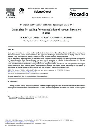
II-2.Results and discussionA good sealing glass must initially flow to form an adequate seal, before crystallizing toprovide sufficient rigidity for mechanical integrity. The dilatometic softening temperaturecorresponds to a viscosity of 108-9 Pa·s [10] and is used here as a guide for determining thesealing temperature of the SOFC glasses. The desired operational temperature of many SOFCdesigns is in the range from 700 to 800 C. This then fixes the desired sealing temperature in therange from 800 to 900 C. The corresponding dilatometic softening temperature is in the rangefrom 600 to 800 C.Figure 1 shows the dilatometic softening temperature (Td) as a function of B2O3-content fora wide range of glasses. It is clear that the addition of B2O3 decreases the softening temperature.oSoftening Temperature, CThese results are consistent with previous reports in literature [5].900o870 C800700o660 C6000.00.20.40.60.81.0B2O3/SiO2 molar ratioFigure 1: The dependence of the dilatometic softening temperature on B2O3/SiO2 molar ratiofor select SOFC sealing glasses prepared in this study.Figure 2 shows that the addition of ZnO to invert glasses (O/Si 3.5 to 4.0) with 2 mole%B2O3 also decreases the softening temperature (Td).In order to fabricate a reliable hermetic seal, the glasses should flow and bond beforecrystallization. Differential thermal analysis data, like that shown in Figure 3, provide usefulinformation about the processing conditions necessary to produce dense, partially or fullyDE-FG26-04NT42221 Final Report(8)Missouri University of Science & Technology
crystallized seals. The glasses with large differences between their crystallization onsettemperature (on heating), Tc, and glass transition temperature, Tg, generally can be sealed in abroader processing window. Figure 4 summarizes the temperature difference (ΔTs (Tc-Tg)) formany of the glasses prepared in this study. The compositions are represented by their nominalO/Si ratio. Glasses based on pyrosilicate structures (O/Si 3.5) have greater ΔTs, and so aregenerally easier to seal, than glasses based on orthosilicate (O/Si 4.0) structures. Adding B2O3to the compositions increases ΔTs for a fixed O/Si ratio, indicating an increasing resistance orstability to crystallization when the glass is heated above its Tg.oSoftening temperature( C)2 mole% B2O3O/Si 3.53.5 O/Si 4.0O/Si 4.0820800780760740720051015202530ZnO (mole%)Figure 2: The dependence of the dilatometic softening temperature on the ZnO-content forselect SOFC sealing glasses prepared in this study.DE-FG26-04NT42221 Final Report(9)Missouri University of Science & Technology
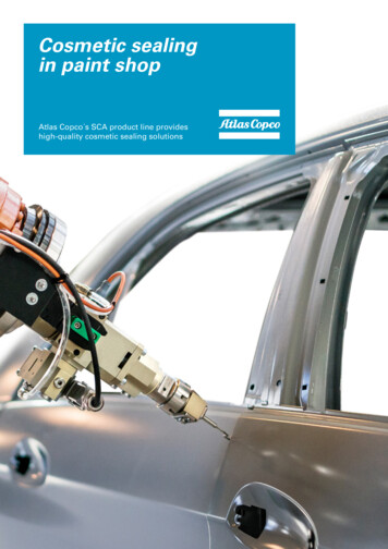
oNormalized ΔT ( C), EXO1.00.80.60.4Glass#81oTc: 850 CoTg: 635 C0.2Glass#500.0ooTg: 700 C600Tc: 890 C800o1000Temperature ( C)Figure 3: DTA curves for two SOFC sealing glass compositions showing the glass transitiontemperature (Tg) and the onset for crystallization (Tx).300oΔTs, (Tx-Tg) C0 - 6 % B2O3 mol% 7.0 % B2O3G#22G#81200G#8710003.03.54.04.5O/Si (molar ratio)Figure 4: Glass processing window, ΔTs, versus O/Si molar ratio for the SOFC sealing glassesprepared in this study.DE-FG26-04NT42221 Final Report(10)Missouri University of Science & Technology
oΔTs, (TC-Tg) C2502001501000.00.10.20.30.40.50.60.7ZnO/SiO 2(molar ratio)Figure 5: The effect of ZnO-content on glass processing range, ΔTs.Adding ZnO to these compositions generally increases ΔTs, as shown in Figure 5. Lara et al.[11] studied the crystallization behaviour of RO-BaO-SiO2 (R Mg, Zn) glasses using DTA andhot-stage microscopy (HSM). They found that glasses with greater ZnO-contents had broaderprocessing windows because of the reduction in Tg, relative to the crystallization temperature andthis is consistent with the results in Figure 5.The coefficient of thermal expansion (CTE) must be compatible with other fuel cellcomponents, such as the yttria-stabilized zirconia (YSZ) electrolyte and the ferritic stainless steelinterconnects, to minimize thermal stress. The target CTE range for an SOFC seal is from 10(YSZ) to 12.5 10-6/ C (interconnects). The coefficient of thermal expansion of alkaline earthcontaining glass-ceramics as a function of average field strength of RO (R Ca, Sr, Ba and Zn) isshown in Fig. 6. Generally the oxides with greater ion field strength (defined as ion chargedivided by the square of the ion radius) reduce the CTE of glasses [12]. The addition of ZnOdecreases the CTE of the glasses. However, when BaO replaces CaO or SrO in the glasscomposition, CTE increases. Similar results have been reported by Lara et al. [11].DE-FG26-04NT42221 Final Report(11)Missouri University of Science & Technology
RO 50 mole%RO 50 mole%)430SSNi-YSZ11oCTE (ppm/ C)12YSZ10980.300.320.340.360.382Average field strength of RO (coul/m )Figure 6: CTE values for ‘invert’ silicate glasses as a function of the average field strength ofthe RO-component (R Ca, Sr, Ba and Zn).Glass-ceramics are formed by crystallization of a glass with properties controlled by theamount and nature of crystalline phases. For alkaline earth-containing glass-ceramics, strontiumoxide is added to form Sr-hexacelsian (Sr2Al2SiO7) with a CTE 11.9 ppm/ C (G#50) orstrontium orthosilicate such as Sr2SiO4 (G#35 and G#81) with a CTE 11.5 ppm/ C. Forbarium-containing glass-ceramics [5], calcium is added to form barium calcium orthosilicatephase (Ba3CaSi2O8) with a CTE 12-14 ppm/ C. In silicate systems, if significantconcentrations of CaO are used without BaO, wollastonite (CaSiO3, CTE 4–9 ppm/ C) canform over long times at SOFC operational temperatures, causing a slow reduction in the CTE ofthe sealing glass [13]. In general, zinc oxide is used to modify the temperature range betweenthe glass transition and crystallization temperature, however, the addition of zinc oxide results inthe formation of calcium-zinc silicate (Ca2ZnSi2O7) or zinc-orthosilicate (Zn2SiO4), phases ofrelatively low CTE. The effects of ZnO-additions on the interfacial interactions between thesealing glass and ferritic interconnect materials is discussed in section V. Two promisingcompositions, glasses #50 and G#81, form CaSrSiO4- and Sr2SiO4-based glass-ceramics,DE-FG26-04NT42221 Final Report(12)Missouri University of Science & Technology
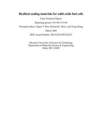
respectively. These materials can be sealed at 850ºC-900, typically in one hour. Figure 7 showsthat the CTE’s of glasses #50 and #81 remain stable at 11- 11.5 x 10⁻⁶/ºC after four months at800ºC.o800 C in air)G lass-Ceram ic G #50G lass-Ceram ic G #81o(200 - 700 C)-6 oCTE (10 / C)141211.01080306090120tim e (days)Figure 7: Coefficient of thermal expansion for sealing glass compositions after heating to800ºC in air for extended times.II-3.Hermetic SealsGlass powders with particle sizes in the range of 10-12 µm, 25-53 µm, and 45-53µm wereprepared from commercially-supplied versions of glass #50 and from a version of glass G#81melted at Missouri S&T, and used for tape-casting experiments. Glass powders were mixed witha solution of PVB binder and acetone and the mixture was applied between substrates ofmaterials used in SOFC stacks, including SS430 and YSZ electrolyte materials. Sealing sampleswere then heated in air at 2ºC/minute to 450ºC and held for 1 hour to remove the binder. Thesamples were then heated to 850 C (glass #81) or 900ºC (glass #50) for thirty minutes to allowthe glass to melt and flow to the edges of the sealed packages, whereupon the samples were thencooled at 2ºC/minute to 800ºC and held for two hours to form the desired glass-ceramic material.Sealed samples were held at 800ºC in either forming gas or air for 24 hours and then werechecked for leaks using a 4 psig helium gas pressure differential across the seal. After 24 hoursat 800ºC, the seals were cooled to room temperature (-10ºC/min) and retested for hermeticity.DE-FG26-04NT42221 Final Report(13)Missouri University of Science & Technology
Samples that did not leak (i.e., held 4 psig pressure for two hours) were reheated to 800ºC andheld for another 24 hour heat treatment/hermeticity cycle. Table 3 summarizes the results ofthese tests. It is significant to note that in general for the samples described in Table 3,hermeticity was lost when the ceramic component of the seal fractured, sometimes as a result ofhandling. Figure 8 shows an electron micrograph of the interface between glass #81 and YSZafter sealing, indicating good wetting and bonding, consistent with the hermeticity results inTable 3.Table 3:Summary of thermal cycling hermeticity tests of glass seals.*Sealing materialsTest conditionsNotes430SS/G50 (10-12µm)/YSZairFailed after 10 cycles; YSZ fracture430SS/G50 (45-53µm)/YSZairFailed after 40 cycles; YSZ fracture430SS/G50 (10-12µm)/YSZforming gasFailed after 10 cycles; YSZ fracture430SS/G50 (45-53µm)/YSZforming gasFailed after 20 cycles; YSZ fracture430SS/G81 (45µm)/YSZair60 cycles without failure430SS/G81 (25µm)/YSZforming gasFailed after 30 cycles; YSZ fracture*Samples were held for 24 hours at 800ºC under forming gas or compressed air, and tested for hermeticity.Figure 8: SEM micrograph of the interface between 8%YSZ(left) and glass #81(right) aftersealing at 850 C for 1h in air.DE-FG26-04NT42221 Final Report(14)Missouri University of Science & Technology
III. Crystallization StudiesKnowledge of the crystallization processes in glasses is important for developing glassceramics as well as improving their performance in a variety of applications, including formationof seals for solid oxide fuel cells. Generally, the sintering process should be completed beforecrystallization occurs to obtain a dense seal [14]. Uncontrolled crystallization during the initialsintering process can lead to the formation of a porous sealing layer that can adversely affect theSOFC operation. The joining process also requires the sealant to flow to the edge of the seal,which generally favors a slowly crystallizing glass [15]. In addition, the viscous flow of glasscan reduce the thermal stress generated by the thermal cycling during the routine SOFCoperation and so preventing full crystallization may be advantageous. Finally, as indicatedabove, the difference in the crystallization temperature (Tc) and the glass transition temperature(Tg) is associated with the glass forming tendency (GFT) [ 16 ].Glasses that have largedifferences (ΔTS) can be sealed in a wider temperature window, allowing a more robustmanufacturing process. Therefore, knowledge of the crystallization processes for sealing glassesis critical for composition design and process control.Thermal analysis is an important tool for studying the kinetics of crystallization inglasses. Kinetic parameters for crystallization can be obtained by DTA (differential thermalanalysis) or DSC (differential scanning calorimetry). The analysis is generally based on eitherthe change of peak area [17] or the shift of peak temperature with heating rate [18]. Severalmodels to describe the crystallization behavior have been developed based on the classicalisothermal transformation kinetic theory, as described by the Johnson-Mehl-Avrami (JMA)equation [19]:x 1- exp[-(kt)n](1)where x is the volume fraction transformed after time t, n is the Avrami exponent, and k is thereaction-rate constant. Non-isothermal approaches, such as the one developed by Kissinger [18],are generally favored because of their operational simplicity and convenience compared to theconventional isothermal approach. Slightly modified versions of this Kissinger model wereDE-FG26-04NT42221 Final Report(15)Missouri University of Science & Technology
developed by Matusita and Sakka [20] that account for crystal growth occurring on a fixednumber of nuclei, or nucleation and crystal growth processes that occur simultaneously.Recently, a new DTA method that combines isothermal (heat-treatment for crystallization)and non-isothermal (during the DTA scan) heat treatments was developed, which satisfiesisothermal crystallization conditions required for the application of JMA model [21]. In thismethod, changes in crystallization peak areas collected by DTA from samples followingisothermal heat treatments are used to determine changes in crystal fraction, which, in turn, areanalyzed using the JMA equation, to obtain those kinetic parameters for crystallization. This newapproach not only excludes the non-isothermal nature of typical DTA (or DSC) experiments, buteliminates most of the common problems that make isothermal studies laborious and timeconsuming. Previous work on Li2O-2SiO2 glasses established the viability of this approach [21].In this report section, the application of the new methodology to the crystallization behaviour ofan SOFC sealing glass developed at Missouri S&T is reviewed.III-1. Sample Preparation and CharacterizationFor crystallization experiments a 50-g sample of glass #27 (Table 1) was prepared asdescribed above and the melt was then quenched on a steel plate. Glass powders were crushedand sieved to different size ranges. A fraction of the glass powder was ball-milled with YSZmedia for 24 hours to yield a powder with an average particle size of 10 μm, as measured bylaser light scattering (Beckman-Coulter model LS230). Composite samples were prepared bymixing glass powders (45-53 μm) with 10 vol% Ni metal powder (3 µm diameter) or YSZpowder (1 µm diameter) in acetone for 24 hours to produce uniform mixtures. The resultingslurry was dried in an oven at 90 C for several days to produce samples for DTA analyses. Thecrystallization characteristics of glass powders were studied using differential thermal analyses(DTA-7, Perkin Elmer, Inc.). The measurements were conducted in nitrogen, using a platinumcrucible and a sample weight of 45-50 mg. A typical experiment included heating the glasspowder in the DTA from room temperature to a predetermined target temperature between740 C to 880 C, holding the sample at this isothermal set temperature for various times toachieve partial crystallization, then cooling it to a temperature ( 500 C) that is about 350 Cbelow the onset temperature for crystallization, and finally reheating the sample until theDE-FG26-04NT42221 Final Report(16)Missouri University of Science & Technology
crystallization is complete. The heating and cooling cycles for all the experiments in the presentstudy were performed at a rate of 10 C/min. Crystallized phases were identified by x-raydiffraction (XDS 2000, Scintag, Inc.). A quenched monolithic glass sample was also heated to900 C for 30 minutes, then quenched. This partially-crystallized sample was embedded in epoxyand polished (finished by 1200 grit SiC paper) before it was analyzed using Scanning ElectronMicroscopy (S-4700, Hitachi, Inc.).III-2. Results and discussionI
II. THERMAL PROPERTIES OF 'INVERT' SEALING GLASSES II-1. Glass Preparation and Characterization Glasses were prepared at Missouri S&T for preliminary evaluations. For a typical melt, 50 gram samples were prepared from batch mixtures of reagent grade alkaline earth carbonates, boric acid, zinc oxide, silica and various other oxides.