Transcription
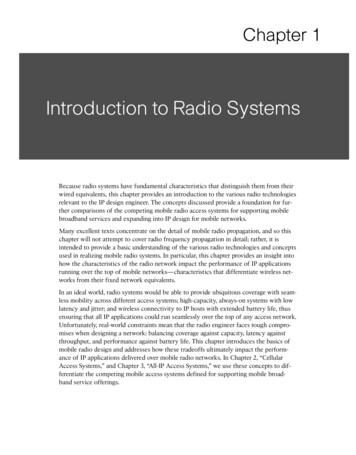
Chapter 1Introduction to Radio SystemsBecause radio systems have fundamental characteristics that distinguish them from theirwired equivalents, this chapter provides an introduction to the various radio technologiesrelevant to the IP design engineer. The concepts discussed provide a foundation for further comparisons of the competing mobile radio access systems for supporting mobilebroadband services and expanding into IP design for mobile networks.Many excellent texts concentrate on the detail of mobile radio propagation, and so thischapter will not attempt to cover radio frequency propagation in detail; rather, it isintended to provide a basic understanding of the various radio technologies and conceptsused in realizing mobile radio systems. In particular, this chapter provides an insight intohow the characteristics of the radio network impact the performance of IP applicationsrunning over the top of mobile networks—characteristics that differentiate wireless networks from their fixed network equivalents.In an ideal world, radio systems would be able to provide ubiquitous coverage with seamless mobility across different access systems; high-capacity, always-on systems with lowlatency and jitter; and wireless connectivity to IP hosts with extended battery life, thusensuring that all IP applications could run seamlessly over the top of any access network.Unfortunately, real-world constraints mean that the radio engineer faces tough compromises when designing a network: balancing coverage against capacity, latency againstthroughput, and performance against battery life. This chapter introduces the basics ofmobile radio design and addresses how these tradeoffs ultimately impact the performance of IP applications delivered over mobile radio networks. In Chapter 2, “CellularAccess Systems,” and Chapter 3, “All-IP Access Systems,” we use these concepts to differentiate the competing mobile access systems defined for supporting mobile broadband service offerings.
2IP Design for Mobile NetworksSpectrumRadio Frequency Spectrum is a key distinguishing factor used to compare alternativemobile radio systems. Radio spectrum for communications ranges from approximately 30Hz (termed Extremely Low Frequency [ELF]) to above 100 GHz (termed Extremely HighFrequency [EHF]). Because of its capability to provide very wide area coverage and penetrate sea water, ELF has been used for global systems for providing low-rate submarinecommunications. EHF, on the other hand, can be used for Line-of-Sight (LoS) microwavecommunications. Table 1-1 shows the complete range of radio frequency spectrum usedin communication systems and provides some examples of spectrum use.Table 1-1Radio Frequency SpectrumBand NameFrequency RangeExample Communication UseExtremely Low Frequency3–30 HzSubmarine communicationsSuper Low Frequency30–300 HzSubmarine communicationsUltra Low Frequency300–3,000 HzUnderground communicationsVery Low Frequency3–30 kHzNavigationLow Frequency30–300 kHzAM broadcastingMedium Frequency300–3,000 kHzAM broadcastingHigh Frequency3–30 MHzShortwave broadcast; amateur radioVery High Frequency30–300 MHzPrivate mobile radio; FM and televisionbroadcastingUltra High Frequency300–3,000 MHzTelevision broadcasting, cellular radio, andwireless LANsSuper High Frequency3–30 GHzWireless LANs; point-to-point and pointto-multipoint microwaveExtremely High Frequency30–300 GHzPoint-to-point microwaveTable 1-1 highlights how the characteristics of the different bands of the radio spectrumvary. In general, the lower the frequency, the better the range (for example, in the extremecase, a single ELF transmitter is able to cover the entire planet), but the bandwidths available are limited (for example, the same ELF systems typically provided a global systemwith total system capacity below 50 bps). Conversely, EHF systems can provide incredible capacity, but they incur significant attenuation by atmospheric effects due, for example, to extreme humidity, rain, or molecular absorption, and thus are prone to significantlosses in non-Line-of-Sight (LoS) deployments.
Chapter 1: Introduction to Radio SystemsIn between these extremes is the “sweet spot” for the radio spectrum for conventionalmobile systems, with the Ultra High Frequency (UHF) band ranging from 300 MHz to 3GHz and providing what many consider to be the best compromise between usable bandwidths and propagation characteristics required for wide area coverage.As a consequence, the UHF spectrum is a scarce resource with many competing users. Inorder to rationalize spectrum usage, the Radio Communications Sector of theInternational Telecommunications Union (ITU-R) has identified key bands that can preferably be used for International Mobile Telecommunications (IMT) operation. These IMTbands cover operation for the following: IMT-2000 systems: Covering legacy “3G” technologies, including Wide Band CodeDivision Multiple Access (WCDMA), cdma2000 1xrtt technologies, and mostrecently WiMAX. IMT-enhanced systems: Covering those systems offering improved mobile broadband services, including High-Speed Packet Access (HSPA) and EVolution-Data Only(EV-DO) technologies. IMT-advanced systems: Covering those systems offering very high-rate mobilebroadband operation, including rates in excess of 1 Gbps to low-mobility users.Note In Chapters 2 and 3, we provide more detail describing alternative mobile radioaccess systems; it will become apparent that none of the current competing systems,including WiMAX and Long-Term Evolution (LTE), meet the minimum requirements forIMT-advanced systems.The spectrum for use by the IMT-2000 technologies was first identified by the ITU atthe World Administrative Radio Conference (WARC) in 1992 and further augmented atthe World Radiocommunication Conferences (WRC) in 2000 and 2007. Even when spectrum has been identified for use by IMT systems, it might not be available for sole use ofmobile radio systems. However, the identification of spectrum by ITU-R, as illustrated inTable 1-2, provides equipment manufacturers with guidance on the range of frequencybands that are likely to be used in deploying IMT services, hopefully leading toeconomies of scale and consequential decrease in the overall cost of production of specialized IMT equipment.Table 1-2IMT Spectrum AllocationsFrequency RangeRegional Rules450–470 MHzAll regions610–790 MHzNine countries in Region 3 (Asia and Australasia): Bangladesh, China,Rep. of Korea, India, Japan, New Zealand, Papua New Guinea,Philippines, and Singaporecontinues3
4IP Design for Mobile NetworksTable 1-2IMT Spectrum Allocations (continued)Frequency RangeRegional Rules698–790 MHzRegion 2 (Americas)790–960 MHzAll regions1,710–2,025 MHzAll regions2,110–2,200 MHzAll regions2,300–2,400 MHzAll regions2,500–2,690 MHzAll regions3,400–3,600 MHzNo global allocation, but over 80 administrations in Region 1 (Europeand Africa), plus nine in Region 3, including India, China, Japan, andRep. of KoreaEven with the 885 MHz of spectrum allocated to IMT across all regions, as indicated inTable 1-2, the ITU has performed an analysis of the growing requirements for spectrum toaddress IMT deployments. ITU-R report M.2078 contains the results of that analysis,both for “legacy” systems in terms of pre-IMT systems, IMT-2000 systems, and IMTenhanced systems that are already being deployed, as well as the spectrum that will berequired for future IMT-advanced deployments. These results indicate that although thecombined allocations of WARC-1992, WRC-2000, and WRC-2007 are sufficient for legacy deployments, the new IMT advanced systems are expected to require up to 420 MHzof additional spectrum to be allocated by year 2015 and up to 840 MHz of additionalspectrum to be allocated by year 2020.ITU-R Report M.2078 uses the service categorization defined in ITU-R Report M.2072,“World mobile telecommunication market forecast,” which includes seven service categories, as shown in Table 1-3, including services at speeds of up to 100 Mbps for superhigh multimedia services!Table 1-3ITU Mobile Service CategorizationPeak Bit RateService Category 16 kbpsSpeech 128 kbpsMultimedia messaging; low multimedia, low rate data 384 kbpsMedium multimedia 2 MbpsHigh multimedia 10 MbpsVery high multimedia 30 MbpsUltra high multimedia 100 MbpsSuper high multimedia
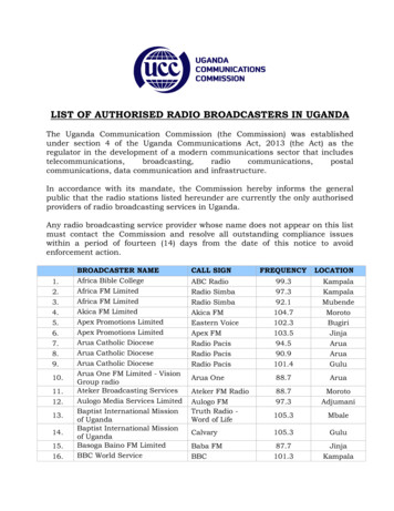
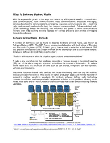
Chapter 1: Introduction to Radio SystemsIf the ITU estimates prove accurate, it is evident that future World RadiocommunicationConferences will be required to define increasing spectrum allocations for future IMToperations. These systems will be less telecommunications-focused and increasingly datacentric as capabilities evolve toward supporting super high multimedia service offerings.PropagationBecause of its relative scarcity, mobile systems are required to re-use the allocated radiospectrum across a particular network of cell sites. Radio frequency signals need to propagate between the cell site antenna and the mobile wireless terminal. As the signals propagate, they exhibit a path loss as the emitted energy is dispersed over an increasing area.Estimating the path loss is critical in determining both the coverage provided by a singlecell site and the bandwidth available to the IP services offered in that cell coverage area.The benchmark of propagation loss is that of free space—in other words, the loss in aregion that is free from all objects that might absorb or reflect the radio energy. Becausethe emitted energy from an isotropic antenna is dispersed over the surface of a sphere(with the transmitting antenna at the center of the sphere), the received energy is inversely proportional to the surface area of the sphere (4 π r2, where r is the radius of thesphere), as illustrated in Figure 1-1. Using this approach, you can see that the free spacepath loss follows an inverse square law with changing distance from the antenna, r.4πr2dTransmitter:EmittingPtransmitter dBFigure 1-1HreceiverHtransmitterrFree Space LossReceiver:ReceivingPreceiver dB5
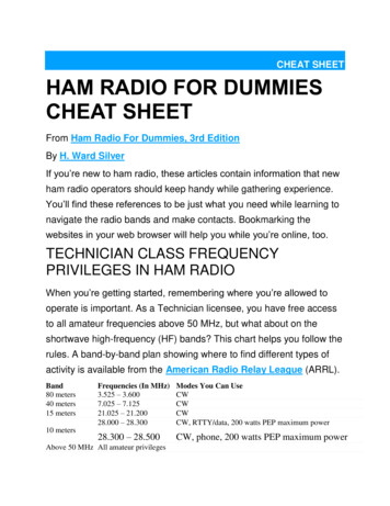
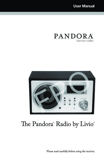
IP Design for Mobile NetworksRadio propagation is often defined in logarithmic ratios, termed decibels (dB). Whenreferring to power, a decibel is defined as follows:X dB 10 Log10(X/X0)Because path loss is an important quantity in defining the coverage and capacity ofmobile radio systems, a useful unit used to compare different environments is to definethe decrease in received power over a “decade,” where a decade corresponds to anincrease in the order of magnitude of distance—for example, when going from 1 mile to10 miles, 10 kilometers to 100 kilometers, or 13 furlongs to 130 furlongs. Using such anapproach and the inverse square law, you can see that the free space loss is equivalent to apath loss of 20 dB/decade; that is, the power received at 10 miles from a transmitter is100 times less than the power received at 1 mile away from the same transmitter.Outdoor CoverageUnfortunately, cellular networks are not built in free space and instead need to accommodate reflections from the ground. Figure 1-2 shows such a model illustrating a direct pathbetween transmitter and receiver as well as a ground eceiverTransmitterdFigure 1-2Propagation with Ground ReflectionThe resulting estimate of the received power at the receiver is approximately equal to:Preceiver Ptransmitter * Gain * (Htransmitter * Hreceiver/ d2)2where the gain corresponds to the antenna gains in the system and represents the directionality of the antennae radiation patterns when compared to an isotropic antenna.Counterintuitively, the addition of the ground reflection produces an inverse fourthpower relationship between the power at the receiver and the distance, d, between thetransmitter and receiver. Instead of the received power diminishing at a rate of 20dB/decade as predicted by a free-space model, mobile communication systems frequently
Chapter 1: Introduction to Radio Systemsexhibit received power diminishing at a rate approaching 40 dB/decade as the receivermoves away from the transmitter.Note The received power is also a function of the square of the product of transmit andreceive antenna heights. This is why cellular antennas have conventionally been located onhilltops and raised high on towers, and if you are in a region of poor coverage, why it isoften better to try receiving cell phone service on the top floor of a building.Empirical modeling of radio propagation has been performed by Okumura1 and Hata.2The typical urban Hata model defines the distance (d, in meters) related propagation lossas follows:(44.9 – 6.55 Log10 (h base station)) Log10 (d)Using an example 10-meter base station height, the empirical data indicates that the actual path loss should decrease at 38 dB/decade.This means that when moving from 1 kilometer to 10 kilometers away from a base stationantenna, the signal will in fact decrease by a factor approaching 10,000. Although thisallows for the scarce spectrum resources to be re-used as neighboring cell site emissionsare rapidly attenuated, it also ensures that the cellular designers are constantly battling toprovide improved coverage with lower path loss while limiting the number of cell sitesrequired to cover a particular area.Frequency-Dependent Propagation LossWe can see from Table 1-1 that in general terms, lower frequencies propagate better thanhigher frequencies. This intrinsic property has resulted in different systems competing forthe sub 1 GHz frequencies, which offer improved propagation characteristics comparedwith other IMT spectrum allocations.For example, recent analysis of propagation in the UHF band has been performed,3 indicating that there is a 26.7 dB increase in path loss when comparing IMT systemsdeployed in the IMT-defined 698–790 MHz band with those deployed in the2,500–2,690 MHz band.Given a typical macro-area propagation loss of 38 dB/decade, it is evident that a changein operating frequency from 698 MHz to 2,500 MHz needs to be compensated bydecreasing the cell radius by a factor of 10(26.7/38) or five times! The maximum throughputof an individual cell is bounded and will be reduced as the ratio between the wanted signal and the interfering signals decreases. In a lightly loaded system, the interfering signalswill be low and hence lower frequencies can provide service over a large coverage area.We describe such deployments as being coverage limited, where the performance of theoverall system is limited by the attenuation of the wanted signal.7
8IP Design for Mobile NetworksHowever, as load increases, neighboring cells generate more interference and more cellswill be needed to provide the required capacity. In such circumstances, the systembecomes limited by interference. We describe such deployments as capacityconstrained, where the rapid adoption of higher bandwidth IP services means that themaximum attainable cell radius is artificially reduced—for example, by reducing themaximum power—in order to support the required teletraffic density.The same characteristic that allows a lower frequency signal to propagate over increaseddistances now also results in the increased effects of interference, as the emissions fromneighboring cell sites are similarly attenuated to a lesser degree because of the lower frequency. Hence, the inherent advantages of operating at lower frequencies, which providedimproved coverage in a lightly loaded system, diminish over time as the capacity increases.When these characteristics are coupled with the fact that larger bandwidth allocations areoften available at higher frequencies, it is evident that the optimum choice of frequencythat delivers the lowest total cost for a specific radio system is a complex tradeoff.Note The same analysis that indicated that 698 MHz systems had a 26.7 dB advantage interms of path loss over 2,500 MHz systems also shows that as the 698 M
IMT-2000 systems:Covering legacy "3G" technologies, including Wide Band Code Division Multiple Access (WCDMA), cdma2000 1xrtt technologies, and most recently WiMAX. IMT-enhanced systems:Covering those systems offering improved mobile broad-band services, including High-Speed Packet Access (HSPA) and EVolution-Data Only (EV-DO) technologies.