Transcription
Operation GuideWBOX IP CameraIntelligent AnalysisOperation GuideV1.12017-03-21
OverviewOverviewPurposeThis document describes the installation and use of the Intelligent Analysis device as well as precautions.Terminology Field of View – the whole screen that a camera is capable of displaying.Deployment Area – the still area with any shape in the field of view set by a user.Deployment Line – the line with a static direction in the field of view set by a user.Target – the moving object of a certain type (person, car, person or car) appearing in the field of view.False Alarm – a false alarm generated because of interference sources (such as illumination change, leafwaggle and shadow).Alarm missing – an alarm meeting user-defined target trigger settings but not alarm.FunctionsBelow is the list of all the functions of Intelligent Analysis.IDFunction NameAvailability1Perimeter 2Single Virtual Fence 3Double Virtual Fences 4Loiter 5Multiple Loiter 6Object Left 7Object Removed 8Abnormal Speed 9Converse 10Illegal Parking 11Signal Bad Issue V1.1 2017-03-21Remarkincludes Camera Tamper and Camera Shifti
OverviewOperating Environment Intelligent Analysis is currently available on Ambarella S2 onlyOperating System: Microsoft Windows 7/Windows XP (32/64-bit operating system supported)CPU: Intel core i3 and aboveMemory: 1 GB and aboveDisplay Resolution: 1024x768 or above supportedNOTE The software does not support pure 64-bit system. The 64-bit system mentioned above supports 32-bitsoftware.PrecautionsPrecautions for Installation The camera stays level with the horizon, without inclination.The installation height is more than 2 meter indoors and within 5-8 meters outdoors. If climbing over thewall needs to be monitored, the camera height can be 2 meter higher than the wall.The angle of depression is larger than 15 .Do not install the device against the light.Try to install the device in a place where the light reflection from ground is weak in the case of indoorinstallation.Try to keep the sky out of the field of view, because false alarms may be generated due to illuminationchanges or cloud movement.Other Precautions Try to disable automatic white balance, the switch of which tends to cause alarm missing.Set the camera to fixed focus.Do not switch from color mode to black & white mode frequently, otherwise, alarm missing occurs.Try not to use the infrared all-in-one machine outdoors, which attracts insects and causes false alarms.The target cannot be oversize or undersize. The minimum target detectability is 8x8 pixels. The targettakes up 1/20-1/2 of the screen in height, excess of which leads to alarm missing.The background modeling after parameter setting needs 4-8 seconds, during which a triggered alarm isnot reported.A certain period of time is required from target appearance to recognition, so the duration of a targetappearing in the field of view normally needs to be more than 2 seconds.Avoid too many moving targets in the field of view, which may lead to alarm missing.The fill-in light at night needs to be uniform.The wide-angle lens with short focal length (less than 4 mm) is recommended for small indoor space.Issue V1.1 2017-03-21ii
ContentsContentsOverview . Error! Bookmark not defined.1 Parameter Settings . 11.1 Parameter Settings . 12 Function Settings . 32.1 Perimeter . 32.2 Single Virtual Fence . 62.3 Double Virtual Fences . 92.4 Loiter . 132.5 Multiple Loiter. 172.6 Object Left . Error! Bookmark not defined.02.7 Object Removed . Error! Bookmark not defined.32.8 Abnormal Speed. 252.9 Converse. 282.10 Illegal Parking . 312.11 Signal Bad . 34Issue V1.1 2017-03-21iii
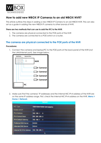
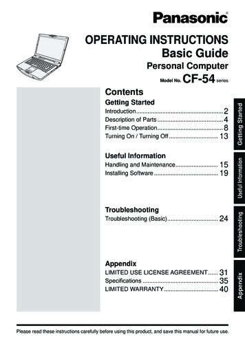
Parameter Settings1 Parameter Settings1.1 Parameter SettingsAfter logging in to the device, select Intelligent Analysis Advanced to access the Advanced settinginterface, as shown in Figure 1-1.Figure 1-1 Advanced Parameter Setting InterfaceIssue V1.1 2017-03-211
Parameter SettingsScene SettingYou can set the scene of the camera, ID, real size in scene and depth of field validate on Scene settings. Table1-1 describes the specific parameters.Table 1-1 Advanced Parameter DescriptionParameter DescriptionSettingScene[How to set]The scene which camera installedSelect indoor/outdoor base on theEnvironment.Select from the drop-down list.[Default value]OutdoorIDReal Sizein scene(cm)Mark the line base on the ID of line;select the according line by the ID.[How to set]Length of line according to the realsize in scene. The default value is 0and the setting value is 0-99999centimeters.[How to set]Select from the drop-down list.Enter a value in the area box.[Default value]0Depth offieldvalidateValidate the size of setting area inthe scene according the markingline.[How to set]Click and enter a value in the areabox.Setting methods and rulesSet the advanced parameters before setting function parameters. Draw lines in advanced parametersinterface so that the true object has a mapping relation with the image object. The method and rules fordrawing line as below: 2-4 vertical lines or 2 vertical lines and 2 ground lines need to be entered. In the case of low marking requirement, two vertical lines can meet most scene requirements.Normally, the vertical line is marked based on person height. The lines are distributed near and far. Two vertical lines are in the scene, one near and the other far.On the screen, draw a vertical line along the target object height, measure the actual length of thistarget, and enter the actual length in Real Size in Scene box for saving. Similarly, two horizontal lineson the ground are in the scene, one near and the other far. Measure and enter the actual length. Click a marking line (turning red after clicking)and click Delete to delete the marking line Click a marking line (turning red after clicking), to modify the marking line data. You can also modifythe line parameters by selecting a number and enter the actual size in Real Size in Scene box on theadvanced parameter interface.Issue V1.1 2017-03-212
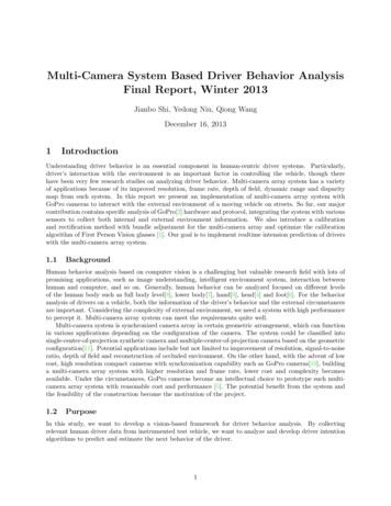
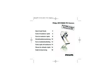
Function Settings2 Function Settings2.1 PerimeterDescriptionThe Perimeter function refers to that an alarm is generated when the targets of specified types (such asperson, car, and both person and car) enter the deployment area.ProcedureStep 1 Select Intelligent Analysis Perimeter to access the Perimeter interface, as shown in Figure 2-1.Figure 2-1 Perimeter Setting InterfaceIssue V1.1 2017-03-213
Function SettingsStep 2 Set all parameters for perimeter. Table 2-1 describes the specific parameters.Table 2-1 Perimeter Parameter DescriptionParameterDescriptionSettingEnableEnable the button to enable the alarm.[How to set]Click Enable to enable.[Default value]OFFLimit TargetTypeLimit TargetSizeUpload TargetInfoEffective alarms are set based on targettype, with options of Person or Car,person, car. When the device is usedindoors, because of small space and largetargets, alarms are triggered by personsometimes even if car is selected, leadingto false alarms. It is recommended to setthe target type to person for indoor use.[How to set]The target size for triggering an effectivealarm is set based on the actual targetsize. The minimum size is 1000 squarecentimeters and the maximum100000square centimeters. When setting thetarget size, you need to well set “Real sizein scene” in Advanced parameter;otherwise no alarms may be generated.[How to set]Enable the function of uploading target[How to set]information by clickingbelow thereal-time video in a flash browser to turnClick to enable UploadTarget Info.into. When an alarm istriggered, the target movement trace canbe displayed (The trace can be seen onlywithin the deployment area anddisappears after the target leaves thedeployment area)Click to enable LimitTarget Type.[Default value]OFFClick to enable LimitTarget Size.[Default configuration]OFF[Default value]OFFOutputChannelIf you check to set the Output Channel andthe device is connected to an externalalarm indicator, the alarm indicator signalswhen an alarm is triggered.[How to set]Alarm RecordEnable the button to enable the alarmrecord.[How to set]Click to select an ID.Click to enable AlarmRecord.[Default value]OFFIssue V1.1 2017-03-214
Function SettingsParameterDescriptionSettingSMTPEnable the button to enable SMTP sever.[How to set]Click to enable SMTP.[Default value]OFFFTP UploadEnable the button to enable File TransferProtocol.[How to set]Click to enable FTPUpload.[Default value]OFFPTZ TypeValueSet PTZ type for dome cameras and selectcorresponding PTZ type:Preset/Scan/Track/Tour.[How to set]Select corresponding value from valueafter select PZT type.[How to set]Select from the dropdown list.Select from the dropdown list.Step 3 Set a deployment area.Move the cursor to the drawing interface and click to generate a point, move the cursor to draw aline, and then click to generate another point. This is how a line is generated. In this way, continue todraw lines to form any shape, and right-click to finish line drawing, as shown in Figure 2-2.Figure 2-2 Deployment Area Setting InterfaceNOTE Issue V1.1 2017-03-21A drawn line cannot cross another one, or the line drawing fails.Any shape with 32 sides at most can be drawn.The quantity of deployment areas is not limited yet and will be described in future when a limit isapplied.5
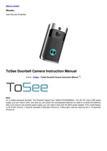
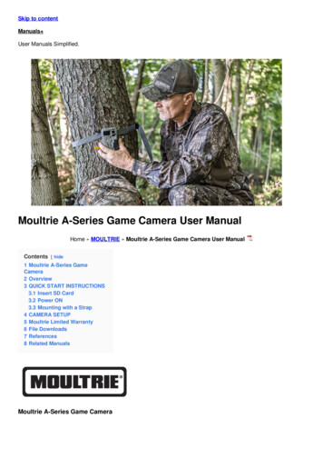
Function SettingsStep 4 Set deployment time.Method 1: Click left mouse button to select any time point within 0:00-24:00 from Monday toSunday as shown in Figure 2-3.Method 2: Hold down the left mouse button, drag and release mouse to select the deployment timewithin 0:00-24:00 from Monday to Sunday.NOTEWhen you select time by dragging the cursor, the cursor cannot be moved out of the time area.Otherwise, no time can be selected.Method 3: Click in the deployment time page to select the whole day or whole week.Deleting deployment time: Click again or inverse selection to delete the selected deployment time.Figure 2-3 Deployment Time Setting Interface2.2 Single Virtual FenceDescriptionA Single Virtual Fence is a line that is set at a concerned position within the monitored field of view andspecifies the forbidden travel direction. An alarm is generated when the targets of specified types (such asperson or car) cross this line.ProcedureStep 1 Select Intelligent Analysis Single Virtual Fence to access the Single Virtual Fence setting interface,as shown in Figure 2-4.Issue V1.1 2017-03-216
Function SettingsFigure 2-4 Single Virtual Fence Setting InterfaceStep 2 Set all parameters for the single virtual fence. Table 2-2 describes the specific parameters.Table 2-2 Description of Parameters for Single Virtual FenceParameterDescriptionSettingEnableEnable the button to enable the alarm.[How to set]Click Enable toenable.[Default value]OFFLimit TargetTypeLimit TargetSizeIssue V1.1 2017-03-21Effective alarms are set based on target type,with options of Person or Car, person, car.When the device is used indoors, because ofsmall space and large targets, alarms aretriggered by person sometimes even if car isselected, leading to false alarms. It isrecommended to set the target type toperson for indoor use.[How to set]The target size for triggering an effectivealarm is set based on the actual target size.The minimum size is 1000 squarecentimeters and the maximum100000square centimeters. When setting the targetsize, you need to well set “Real size in scene”in advanced parameters; otherwise noalarms may be generated.[How to set]Click to enable LimitTarget Type.[Default value]OFFClick to enable LimitTarget Size.[Defaultconfiguration]OFF7
Function SettingsParameterDescriptionSettingUpload TargetInfoEnable the function of uploading target[How to set]information by clickingClick to enableUpload Target Info.below the real-time video in a flash browser to turn[Default value]into. When an alarm is triggered, theOFFtarget movement trace can be displayed (Thetrace can be seen only within thedeployment area and disappears after thetarget leaves the deployment area)OutputChannelIf you check to set the Output Channel andthe device is connected to an external alarmindicator, the alarm indicator signals whenan alarm is triggered.[How to set]Alarm RecordEnable the button to enable the alarmrecord.[How to set]Click to select an ID.Click to enable AlarmRecord.[Default value]OFFSMTPEnable the button to enable SMTP sever.[How to set]Click to enableSMTP.[Default value]OFFFTP UploadEnable the button to enable File TransferProtocol.[How to set]Click to enable FTP.[Default value]OFFPTZ TypeValueIssue V1.1 2017-03-21Set PTZ type for dome cameras and selectcorresponding PTZ type:Preset/Scan/Track/Tour.[How to set]Select corresponding value from value afterselect PZT type.[How to set]Select from thedrop-down list.Select from thedrop-down list.8
Function SettingsStep 3 Set a deployment area.Drawing a line: Move the cursor to the drawing interface, hold down the left mouse button, andmove the cursor to draw a line. When you release the left mouse button, a single virtual fence isgenerated.Setting a single virtual fence: Click a line (and the trip line turns red) to select the single virtual fenceand set its direction as Positive, Reverse or Bidirectional, or delete the selected line. You can alsopress and hold left mouse button at the endpoint of a single virtual fence and move the mouse tomodify the position and length of this single virtual fence. You can right-click to delete the singlevirtual fence, as shown in Figure 2-5.Figure 2-5 Deployment Area Setting InterfaceNOTE A single virtual fence is not within any deployment area, therefore, when an alarm isgenerated, the trace always exists. Only when the target object moves out of the field ofview, the trace disappears.Try to draw the single virtual fence in the middle, because the recognition of a target takestime after target appearance on the screen and an alarm is generated only when the objectis recognized to have crossed the single virtual fence.The single virtual fence which detects person foot as the recognition target cannot be tooshort, because a short single virtual fence tends to miss targets.Step 4 Set deployment time.For the details, please refer to 2.1 Step 4 Set deployment time.Issue V1.1 2017-03-219
Function Settings2.3 Double Virtual FencesDescriptionDouble Virtual Fences refers to two lines that are set at a concerned special position within the field of viewand specify the forbidden travel direction. When the targets of specified types (such as person or car) movealong the set travel direction and cross these lines in a certain order (line 1 followed by line 2) in pass maxtime, an alarm is generated.ProcedureStep 1 Select Intelligent Analysis Double Virtual Fences to access the Double Virtual Fences settinginterface, as shown in Figure 2-6.Figure 2-6 Double Virtual Fences Setting InterfaceStep 2 Set all parameters for the double virtual fences. Table 2-3 describes the specific parameters.Issue V1.1 2017-03-2110
Function SettingsTable 2-3 Description of Parameters for Double Virtual FencesParameterDescriptionSettingEnableEnable the button to enable the alarm.[How to set]Click Enable toenable.[Default value]OFFLimitTypeTarget Effective alarms are set based on target type,with options of Person or Car, person, car.When the device is used indoors, because ofsmall space and large targets, alarms aretriggered by person sometimes even if car isselected, leading to false alarms. It isrecommended to set the target type toperson for indoor use.[How to set]Target The target size for triggering an effectivealarm is set based on the actual target size.The minimum size is 1000 squarecentimeters and the maximum100000square centimeters. When setting the targetsize, you need to well set “Real size in scene”in advanced parameters; otherwise noalarms may be generated.[How to set]Upload Target Enable the function of uploading targetInfoinformation by clickingbelow the real-[How to set]LimitSizetime video in a flash browser to turnClick to enable LimitTarget Type.[Default value]OFFClick to enable LimitTarget Size.[Defaultconfiguration]OFFClick to enableUpload Target Info.[Default value]into. When an alarm is triggered, theOFFtarget movement trace can be displayed (Thetrace can be seen only within thedeployment area and disappears after thetarget leaves the deployment area)PassMax The maximum time for passing the virtualTime (Sec)fences.[How to set]Click and input avalue.[Default value]5OutputChannelIssue V1.1 2017-03-21If you check to set the Output Channel andthe device is connected to an external alarmindicator, the alarm indicator signals whenan alarm is triggered.[How to set]Click to select an ID.11
Function SettingsParameterDescriptionSettingAlarm RecordEnable the button to enable the alarmrecord.[How to set]Click to enable AlarmRecord.[Default value]OFFSMTPEnable the button to enable SMTP sever.[How to set]Click to enableSMTP.[Default value]OFFFTP UploadEnable the button to enable File TransferProtocol.[How to set]Click to enable FTP.[Default value]OFFPTZ TypeValueSet PTZ type for dome cameras and selectcorresponding PTZ type:Preset/Scan/Track/Tour.[How to set]Select corresponding value from value afterselect PZT type.[How to set]Select from thedrop-down list.Select from thedrop-down list.Step 3 Set a deployment area.Drawing a line: Move the cursor to the drawing interface, hold down the left mouse button, andmove the cursor to draw two lines. When you release the left mouse button, two numbered virtualfences are generated. Choose either of the double virtual fences to set the direction to Positive orReverse.Setting double virtual fences: Click one of the double virtual fences (and the virtual fence turns red)to select this virtual fence and set the direction to Positive or Reverse, or delete the selected line.You can also press and hold left mouse button at the endpoint of a virtual fence and move themouse to modify the position and length of this virtual fence. You can right-click to delete thedouble virtual fences, as shown in Figure 2-7.Issue V1.1 2017-03-2112
Function SettingsFigure 2-7 Deployment Area Setting InterfaceNOTE The two virtual fences are in sequential order. An alarm is generated only when a targetcrosses virtual fence 1 and then virtual fence 2 within the set maximum passing time.The double virtual fences are not within any deployment area, therefore, when an alarm isgenerated, the trace always exists. Only when the target object moves out of the field ofview, the trace disappears.Try to draw double virtual fences in the middle, because the recognition of a target takestime after target appearance on the screen and an alarm is generated only when the objectis recognized to have crossed the double virtual fences.The double virtual fences which detect person foot as the recognition target cannot be tooshort, because short double virtual fences tend to miss targets.Step 4 Set deployment time.For the details, please refer to 2.1 Step 4 Set deployment time.2.4 LoiterDescriptionLoiter allows setting the shortest loitering time for a (single) target of specified type (such as person or car)within the deployment area in the field of view. When the loitering time of a (single) target within this areameets the set shortest loitering time, an alarm is generated.ProcedureStep 1 Select Intelligent Analysis Loiter to access the Loiter setting interface, as shown in Figure 2-8.Issue V1.1 2017-03-2113
Function SettingsFigure 2-8 Loiter Setting InterfaceStep 2 Set all parameters for loitering. Table 2-4 describes the specific parameters.Table 2-4 Loitering Parameter DescriptionParameterDescriptionSettingEnableEnable the button to enable the alarm.[How to set]Click Enable toenable.[Default value]OFFLimit TargetTypeIssue V1.1 2017-03-21Effective alarms are set based on target type,with options of Person or Car, person, car.When the device is used indoors, because ofsmall space and large targets, alarms aretriggered by person sometimes even if car isselected, leading to false alarms. It isrecommended to set the target type toperson for indoor use.[How to set]Click to enable LimitTarget Type.[Default value]OFF14
Function SettingsParameterDescriptionSettingLimit TargetSizeThe target size for triggering an effectivealarm is set based on the actual target size.The minimum size is 1000 squarecentimeters and the maximum100000square centimeters. When setting the targetsize, you need to well set “Real size in scene”in advanced parameters; otherwise noalarms may be generated.[How to set]The time that a target object spends inloitering cannot be less than the shortestloitering time. Setting range: 5-60 seconds.[How to set]The ShortestTime (Sec)Click to enable LimitTarget Size.[Defaultconfiguration]OFFEnter a value in thearea box.[Default value]10sStart the PathJudgmentThe enabling of path analysis makes loiteringjudgment accurate by using the softwarealgorithm, for example, no alarm isgenerated when a person walks along astraight line if the button set ON.[How to set]Upload TargetInfoEnable the function of uploading target[How to set]information by clickingClick to enableUpload Target Info.below the real-time video in a flash browser to turnClick to enable Startthe Path Judgmentand enable pathanalysis.[Default value]into. When an alarm is triggered, theOFFtarget movement trace can be displayed (Thetrace can be seen only within thedeployment area and disappears after thetarget leaves the deployment area)OutputChannelIf you check to set the Output Channel andthe device is connected to an external alarmindicator, the alarm indicator signals whenan alarm is triggered.[How to set]Alarm RecordEnable the button to enable the alarmrecord.[How to set]Click to select an ID.Click to enable AlarmRecord.[Default value]OFFSMTPEnable the button to enable SMTP sever.[How to set]Click to enableSMTP.[Default value]OFFIssue V1.1 2017-03-2115
Function SettingsParameterDescriptionSettingFTP UploadEnable the button to enable File TransferProtocol.[How to set]Click to enable FTP.[Default value]OFFPTZ TypeValueSet PTZ type for dome cameras and selectcorresponding PTZ type:Preset/Scan/Track/Tour.[How to set]Select corresponding value from Value afterselect PZT type.[How to set]Select from thedrop-down list.Select from thedrop-down list.Step 3 Set a deployment area.Move the cursor to the drawing interface and click to generate a point, move the cursor to draw aline, and then click to generate another point. This is how a line is generated. In this way, continue todraw lines to form any shape, and right-click to finish line drawing, as shown in Figure 2-9.Figure 2-9 Deployment Area Setting InterfaceNOTE A drawn line cannot cross another one, or the line drawing fails. Any shape with 32 sides at most can be drawn. The quantity of deployment areas is not limited yet and will be described in future when alimit is applied.Step 4 Set deployment time.For the details, please refer to 2.1 Step 4 Set deployment time.Issue V1.1 2017-03-2116
Function Settings2.5 Multiple LoiterDescriptionMultiple Loiter allows setting the shortest loitering time for multiple targets of specified type (such asperson or car) within the deployment area in the field of view. When the loitering time of the multipletargets within this area meets the set shortest loitering time, an alarm is generated.ProcedureStep 1 Select Intelligent Analysis Multi Loiter to access the Multi Loiter setting interface, as shown inFigure 2-10.Figure 2-10 Multi Loiter Setting InterfaceStep 2 Set all parameters for multiple loitering. Table 2-5 describes the specific parameters.Table 2-5 Multiple Loitering Parameter DescriptionParameterDescriptionSettingEnableEnable the button to enable the alarm.[How to set]Click Enable toenable.[Default value]OFFIssue V1.1 2017-03-2117
Function SettingsParameterDescriptionSettingLimit TargetSizeThe target size for triggering an effective alarm isset based on the actual target size. The minimumsize is 1000 square centimeters and themaximum100000 square centimeters. Whensetting the target size, you need to well set “Realsize in scene” in advanced parameters; otherwiseno alarms may be generated.[How to set]LimitNumbersWhen Limit Numbers is set to OFF, an alarm isgenerated no matter how many people loiter.When Limit Numbers is set to ON, if the minimumnumber is set to 2 and the maximum number isset to 3, an alarm is generated for 2-3 peopleloitering. Other settings are the same as loitering.[How to set]The ShortestTime (Sec)The time that a target object spends in loiteringcannot be less than the shortest loitering time.Setting range: 5-60 seconds.[How to set]Click to enableLimit Target Size.[Defaultconfiguration]OFFClick to enableLimit Numbers.Enter a value inthe area box.[Default value]10sOutputChannelIf you check to set the Output Channel and thedevice is connected to an external alarmindicator, the alarm indicator signals when analarm is triggered.[How to set]AlarmRecordEnable the button to enable the alarm record.[How to set]Click to select anID.Click to enableAlarm Record.[Default value]OFFSMTPEnable the button to enable SMTP sever.[How to set]Click to enableSMTP.[Default value]OFFFTP UploadEnable the button to enable File TransferProtocol.[How to set]Click to enable FTPUpload.[Default value]OFFIssue V1.1 2017-03-2118
Function SettingsParameterDescriptionSettingPTZ TypeSet PTZ type for dome cameras and selectcorresponding PTZ type: Preset/Scan/Track/Tour.[How to set]Select corresponding value from Value afterselect PZT type.[How to set]ValueSelect from thedrop-down list.Select from thedrop-down list.Step 3 Set a deployment area.Move the cursor to the drawing interface and click to generate a point, move the cursor to draw aline, and then click to generate another point. This is how a line is generated. In this way, continue todraw lines to form any shape, and right-click to finish line drawing, as shown in Figure 2-11.Figure 2-11 Deployment Area Setting InterfaceNOTE A drawn line cannot cross another one, or the line drawing fails.Any shape with 32 sides at most can be drawn.The quantity of deployment areas is not limited yet and will be described in future when a limit isapplied.Step 4 Set deployment time.For the details, please refer to 2.1 Step 4 Set deployment time.Issue V1.1 2017-03-2119
Function Settings2.6 Object LeftDescriptionThe Object Left function refers to that an alarm is generated when the dwelling time of an object within thedeployment area meets the set shortest dwelling time.ProcedureStep 1 Select Intelligent Analysis Object Left to access the Object Left setting interface, as shown inFigure 2-12.Figure 2-12 Object Left Setting InterfaceStep 2 Set all parameters for object left. Table 2-6 describes the specific parameters.Table 2-6 Description of Parameters for Object LeftParameterDescriptionSettingEnableEnable the button to enable the alarm.[How to set]Click Enable toenable.[Default value]OFFIssue V1.1 2017-03-2120
Function )Size (cm²)The target size for triggering an effectivealarm is set based on the actual target size.The minimum size is 100 square centimetersand the maximum10000 square centimeters.When setting the target size, you need towell set “Real size in scene” in advancedparameters; otherwise no alarms may begenerated.[How to set]ShortestDwelling Time(Sec)An alarm is generated when the object lefttime is longer than the shortest dwellingtime. Setting range: 5-60 seconds.[How to set]Enter a value in thearea box.Enter a value in thearea box.[Default value]5sUpload TargetInfoEnable the function of uploading target[How to set]information by clickingClick to enableUpload Target Info.below the real-time video in a flash browser to turn[Default value]into. When an alarm is triggered, theOFFtarget movement trace can be displayed (Thetrace can be seen only within thedeployment area and disappears after thetarget leaves the deployment area)OutputChannelIf you check to set the Output Channel andthe device is connected to an external alarmindicator, the alarm indicator signals whenan alarm is triggered.[How to set]Alarm RecordEnable the button to enable the
WBOX IP Camera Intelligent Analysis Operation Guide V1.1 2017-03-21 . Overview Issue V1.1 2017-03-21 i Overview . The camera stays level with the horizon, without inclination. The installation height is more than 2 meter indoors and within 5-8 meters outdoors. If climbing over the