Transcription
Installation, Operation and Maintenance InstructionsLubricated Rotary Vane Medical Vacuum SystemPart number 4107 9000 96Revision 04August 27, 2018
Installation, Operation and Maintenance Manual1.5 - 25 Hp Medical Lubricated Rotary Vane Vacuum System(Not intended for use on dedicated WAGD applications as per NFPA 99 - 2005 edition)This unit is purchased from:Date purchased:Model number:Serial number:Option(s) included:Any information, service or spare parts requests should include the machine serial number and bedirected to:BeaconMedæs1059 Paragon WayRock Hill, SC 29730Telephone: (888) 463-3427Fax: (803) 817-5750BeaconMedæs reserves the right to make changes and improvements to update products soldpreviously without notice or obligation.Part number 4107 9000 96Revision 04August 27, 2018
Medical Lubricated VacuumTable of Contents1.0 Electromagnetic Immunity2.0 Installation2.1 Inspection Upon Receiving2.2 Handling2.3 Location2.4 Locations Above Sea Level2.5 Electrical Requirements2.6 Intake Piping2.7 Exhaust Piping3A.0 Start Up - TotalAlert Embedded Controls3A.1 Prestart-up3A.2 Initial Start-up3A.3 Initial Operation3B.0 Start Up - Basic Controls3B.1 Prestart-up3B.2 Initial Start-up3B.3 Initial Operation4A.0 General Operation - TotalAlert Embedded Controls4A.1 Electrical Control Panel4A.2 Tank Drains4A.3 Emergency Shutdown / Alarms4A.4 Backup Vacuum Switch Set Point Adjustments4B.0 General Operation - Basic Controls4B.1 Electrical Control Panel4B.2 Tank Drains4B.3 Emergency Shutdown / Alarms4B.4 Vacuum Switch Set Point Adjustments5.0 Trouble Shootingi4107 9000 96.04
Medical Lubricated VacuumTable of Contents (continued)6.0 Maintenance6.1 General Maintenance6.2 Oil6.3 Drip Leg and Filters6.4 Bearings6.5 General Inspections7.0 Replacement / Maintenance PartsService Kits for Lubricated Vane Systems8.0 Maintenance RecordAppendix A: TotalAlert Embedded Control SystemA.1 Board ConfigurationsA.2 PCB1 (5.7” Display Controller)A.3 PCB2 (3.5” Display Controller)A.4 Password AccessA.5 Testing AlarmsA.6 MaintenanceA.7 Remote MonitoringA.8 BACnet Activation4107 9000 96.04ii
Medical Lubricated VacuumSafety PrecautionsThe operator should carefully read the entirecontents of this manual before installing, wiring,starting, operating, adjusting and maintaining thesystem.The operator is expected to use common-sensesafety precautions, good workmanship practicesand follow any related local safety precautions.In addition: Before starting any installation ormaintenance procedures, disconnect allpower to the package.All electrical procedures must be in compliancewith all national, state, and local codes andrequirements. A certified electrician should connect allwiring. Refer to the electrical wiring diagram providedwith the unit before starting any installation ormaintenance work. Release all vacuum from the affectedcomponents before removing, loosening,or servicing any covers, guards, fittings,connections, or other devices. Notify appropriate hospital personnel if repairsor maintenance will affect available vacuumlevels. Prior to using the LifeLine Lubricated RotaryVane Medical Vacuum System, the medicalfacility must have a Certifier perform allinstallation tests as specified in NFPA 99. Themedical facility is also responsible for ensuringthat the medical vacuum meets the minimumrequirements for medical vacuum as specifiedin NFPA 99. This is a high speed, rotating piece ofmachinery. Do not attempt to service any partwhile machine is in operation.iii To prevent automatic starting, disconnectall electrical power before performing anymaintenance functions. Do not operate unit without guards, shields orscreens in place. Make sure that all loose articles, packingmaterial, and tools are clear of the package. Check all safety devices periodically for properoperation. Electrical service must be the same as specifiedon the control panel nameplate or damage tothe equipment may occur. Vibration during shipment can loosen electricalterminals, fuse inserts, and mechanicalconnections. Tighten all electrical connectionsprior to energizing the control panel.4107 9000 96.04
Medical Lubricated Vacuum1.0 Electromagnetic ImmunityNote: This section applicable to Lubricated RotaryVane Medical Vacuum Systems with the TotalAlertEmbedded electronic control system.EN 61000-6-2Medical Electrical Equipment needs specialprecautions regarding EMC and needs to beinstalled and put into service according to theEMC information provided in this manual.Portable and mobile RF communicationsequipment can affect Medical ElectricalEquipment.The use of accessories, transducers, and cablesother than those specified by the manufacturer,may result in decreased immunity of the TotalAlertEmbedded control system.The TotalAlert Embedded control system shouldnot be used adjacent to other equipment. Ifadjacent use is necessary, the TotalAlert Embeddedcontrol system should be observed to verifynormal operation in the configuration in which itwill be used.1-14107 9000 96.04
Medical Lubricated Vacuum1.0 Electromagnetic ImmunityEN 61000-6-2 (Cont.)Guidance and manufacturer’s declaration - electromagnetic immunityThe TotalAlert Embedded control system is intended for use in the electromagnetic environment specifiedbelow. The customer or the user of the TotalAlert Embedded control system should assure that it is used in suchan environment.Immunity testIEC 60601test levelCompliance levelElectromagnetic environment - guidanceElectrostaticDischarge (ESD)IEC 61000-4-2 6 kV contact 8 kV air 6 kV contact 8 kV airFloors should be wood, concrete, metal or ceramictile. If floors are covered with synthetic material, therelative humidity should be at least 30 %.Electrical fasttransient/burstIEC 61000-4-4 2 kV for powersupply lines 1 kV for input/output lines 2 kV for power supplylines 1 kV for input/outputlinesMains power quality should be that of a typicalcommercial or hospital environment.SurgeIEC 61000-4-5 1 kV differentialmode 2 kV common mode 1 kV differential mode Mains power quality should be that of a typical 2 kV common modecommercial or hospital environmentVoltage dips, shortInterruptions andvoltage variations onpower supply inputlinesIEC 61000-4-11 5 % UT( 95 % dip in UT)for 0,5 cycle 40 % UT( 60 % dip in UT)for 5 cycles 70 % UT( 30 % dip in UT)for 25 cycles 5 % UT( 95 % dip in UT)for 5 sec 5 % UT( 95 % dip in UT)for 0,5 cycle 40 % UT( 60 % dip in UT)for 5 cycles 70 % UT( 30 % dip in UT)for 25 cycles 5 % UT( 95 % dip in UT)for 5 secMains power quality should be that of a typicalcommercial or hospital environment. If the userof the TotalAlert Embedded control systemrequires continued operation during power mainsinterruptions, it is recommended that the system beinstalled on an emergency power service.Power frequency(50/60 Hz) magneticfieldIEC 61000-4-83 A/m3 A/mPower frequency magnetic fields should be atlevels characteristic of a typical location in a typicalcommercial or hospital environment.NOTE: UT is the a.c. mains voltage prior to application of the test level.4107 9000 96.041-2
Medical Lubricated Vacuum1.0 Electromagnetic ImmunityEN 61000-6-2 (Cont.)Guidance and manufacturer’s declaration - electromagnetic immunityThe TotalAlert Embedded control system is intended for use in the electromagnetic environment specifiedbelow. The customer or the user of the TotalAlert Embedded control system should assure that it is used in suchan environment.Immunity testIEC 60601test levelCompliance levelElectromagnetic environment - guidancePortable and mobile RF communicationsequipment should be used no closer to any part ofthe TotalAlert Embedded control system, includingcables, than the recommended separation distancecalculated from the equation applicable to thefrequency of the transmitter.Recommended separation distanced 1,2 PConducted RFIEC 61000-4-63 Vrms150 kHz to 80 MHz3 Vrmsd 1,2 P80 MHz to 800 MHzd 2,3 P800 MHz to 2,5 GHzwhere P is the maximum output power ratingof the transmitter in watts (W) according tothe transmitter manufacturer and d is therecommended separation distance in metres (m).Radiated RFIEC 61000-4-33 V/m80 MHz to 2,5 GHzField strengths from fixed RF transmitters, asdetermined by an electromagnetic site survey,ashould be less than the compliance level in eachfrequency range.b3 V/mInterference may occur in the vicinity of equipmentmarked with the following symbol:NOTE 1At 80 MHz and 800 MHz, the higher frequency range applies.NOTE 2These guidelines may not apply in all situations. Electromagnetic propagation is affected by absorption andreflection from structures, objects and people.abField strengths from fixed transmitters, such as base stations for radio (cellular/cordless) telephones and land mobileradios, amateur radio, AM and FM radio broadcast and TV broadcast cannot be predicticted theoretically withaccuracy. To assess the electromagnetic environment due to fixed RF transmitters, an electromagnetic site surveyshould be considered. If the measured field strength in the location in which the TotalAlert Embedded control systemis used exceeds the applicable RF compliance level above, the TotalAlert Embedded control system should beobserved to verify normal operation. If abnormal performance is observed, additional measures may be necessary,such as reorienting or relocating the TotalAlert Embedded control system.Over the frequency range 150 kHz to 80 MHz, field strengths should be less than 3 V/m.1-34107 9000 96.04
Medical Lubricated Vacuum2.0 Installation2.1 Inspection Upon ReceivingModular systems are shipped as separate units tofacilitate a variety of installations. Most modularand tank mount units are designed to fit througha standard 36” doorway, though some receivermodules may need to be tipped slightly (15 Hpthrough 25 Hp skid bases measure 43”). Someinterconnecting piping and wiring betweenmodules may be necessary on modular systemsonly.The condition of the LifeLine LubricatedRotary Vane Medical Vacuum System should becarefully inspected upon delivery. Any indicationof damage by the carrier should be noted onthe delivery receipt, especially if the system willnot be immediately uncrated and installed.BeaconMedæs ships all systems F.O.B. factory;therefore, damage is the responsibility of thecarrier, and all claims must be made with them.Lubricated Vane systems may remain in theirshipping containers until ready for installation. IfLifeLine Lubricated Vane systems are to be storedprior to installation, they must be protected fromthe elements to prevent rust and deterioration.Refer to the diagrams supplied with your system fordimensional, wiring and installation information.Place units to ensure high visibility of indicatorsand gauges and for performing maintenance on thesystem. Refer to your installation diagram. If youdo not have one, please contact BeaconMedæsTechnical Support at 888-4-MEDGAS.DO NOT REMOVE the protective covers from theinlet and discharge connection ports of the unituntil they are ready for connecting to the hospital’spipeline distribution system.2.3 LocationThe LifeLine Lubricated Rotary Vane MedicalVacuum system should be installed indoors ina clean, well-ventilated environment. Areas ofexcessive dust, dirt or other air-borne particulateshould be avoided.2.2 HandlingWARNING:USE APPROPRIATE LOAD RATED LIFTINGEQUIPMENT AND OBSERVE SAFE LIFTINGPROCEDURES DURING ALL MOVES.Certain considerations should be given to theplacement of the system. The package may beinstalled in a location that is flat, level, and willsupport its weight. Clearance between the unitand adjacent walls should be no less than 24”to ensure sufficient airflow for cooling. Thereshould be a minimum of three feet of clearancein front of the control panel for safe operationand maintenance. A vertical distance of 24” isrequired above the modules for ventilation andmaintenance.The vacuum package can be moved with eithera forklift or dollies. Keep all packing in placeduring installation to minimize damage. Walkalong the route the unit must travel and notedimensions of doorways and low ceilings. MostLifeLine Lubricated Vane systems are designedto go through 36” doorways (15 Hp through 25 Hpsystems have bases that measure 43”).No special foundation is required. However, allunits must be securely bolted using all mountingholes provided. If a raised concrete pad is used,the module bases must not overhang the concretebase. A method to drain away moisture isnecessary.Most Single Point Connection systems can beseparated to fit through 36” doorways (15Hp through 25 Hp skid bases measure 43”). Ifseparating bases, carefully label all removedelectrical connections for easier re-assembly at thefinal destination.Adequate ventilation is required. The pumps areair-cooled. Therefore, it is very important that the2-14107 9000 96.04
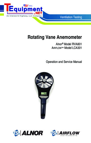
Medical Lubricated Vacuum2.0 Installation2.5 Electrical Requirementsambient temperature should be between 40 Fand 105 F (if the maximum ambient exceeds105 F, contact factory for special instructions).The system should be located as close as possibleto the point of usage to prevent excessive loss ofoperating vacuum due to pressure drop.WARNING:BE SURE THAT ALL POWER IS TURNED OFFPRIOR TO PERFORMING ANY WORK ONTHE ELECTRICAL PANEL!When selecting the location for the system,remember to keep in mind the requirements forservice, such as cleaning, changing filters, andchanging oil.Refer to the electrical diagram provided withthe unit before starting any installation ormaintenance work.Do not operate vacuum pump on a voltage otherthan the voltage specified on the control panelnameplate.2.4 Locations Above Sea LevelAll vacuum pumps above sea level have reducedflow and should be de-rated. After determiningthe correct flow needed for the medical vacuumsystem, multiply this number by the adjustmentfactor located in Table 2.1. After determining thenew flow required, use this number to size themedical vacuum system.All customer wiring should be in compliancewith the National Electrical Code and any otherapplicable state or local codes.Refer to the wiring diagram(s) that came withthe vacuum pump system for pertinent wiringconnections.Table 2.1 Altitude Adjustment FactorAltitude 0007,0008,0009,00010,0004107 9000 96.04NormalBarometricPressure(inches .9023.9823.0922.2321.3920.58Multiplier Usedfor RequiredSCFMElectrical power for the medical system mustbe supplied from the emergency life 61.201.251.301.351.401.45Check the control voltage, phase, and amp ratingsbefore starting the electrical installation, andmake sure the voltage supplied by the hospital isthe same. The wire size should be able to handlepeak motor amp load of all operating units. Referto the vacuum pump system full load amperes onthe wiring diagram.Check all electrical connections within the vacuumsystem that may have loosened during shipment.Qualified electricians only should make powerconnections to the control panel and anyinterconnecting wiring.The control panelhas openings for electrical and alarm/dataconnections. Do not drill additional holes inthe control panel as this may void the systemwarranty. See Figure 2.1 for opening locations.2-2
Medical Lubricated Vacuum2.0 InstallationAlarmWiresDataConnection2.6 Intake PipingElectricalConnectionBefore connecting any piping, the plastic threadprotector installed in the connection port must beremoved. We recommend that the main vacuumline to the receiver should not be reduced belowthat provided on the receiver. Long piping runs mayneed to be increased in size to minimize pressuredrop. Improper line sizing may result in a loss ofcapacity. Ideally, piping should be constructedusing long radius elbows and a minimum numberof turns.All secondary lines should be taken from the top orside of the main line to prevent any accumulatedmoisture from draining towards the pumps. Alllines should slope away from the pumps. Any lowpoints in the piping should be equipped with pipedrains to remove accumulated moisture.All intake vacuum lines must be piped inaccordance with NFPA 99. All pipe must beeither seamless copper tubing or other corrosionresistant metallic tubing, as detailed in NFPA 99.Figure 2.1 Electrical/Alarm/Data Openings2.7 Exhaust PipingEnsure that the emergency generation systemelectrical supply is consistent with the vacuumsystem’s requirements.The exhaust line must be piped outside of thebuilding in accordance with NFPA 99. To ensurethat no restriction of airflow will occur, size thepiping according to Table 2.2. All pipe must beeither seamless copper tubing or other corrosionresistant metallic tubing as detailed in NFPA99. A flexible connector must be installed oneach exhaust port of the vacuum pump beforeconnecting to the main exhaust line leadingoutdoors. Additionally, a drip leg must be installedat each exhaust port connection to allow for thedraining of any accumulated moisture (Refer tothe installation schematics for more details). Theoutside pipe must be turned down and screenedto prevent contamination.The electrical controls for the system were wiredat the factory and were fully tested.Three-phase power supplied from emergencygenerator(s) must match that of the normal supplyto allow for correct direction of the motor rotationat all times.NOTE: It may be necessary to switch two of theleads when performing start-up, if the pumprotation is in the wrong direction.2-34107 9000 96.04
Medical Lubricated Vacuum2.0 InstallationWARNING:THE VACUUM EXHAUST VENT MUST BELOCATED AWAY FROM MEDICAL AIRINTAKES, DOORS, AND OPENINGS INTHE BUILDINGS TO MINIMIZE POSSIBLECONTAMINATION TO THE FACILITY, INACCORDANCE WITH NFPA 99.Table 2.2 Exhaust Pipe LengthLifeLineUnitsTRIPLEXDUPLEXSIMPLEX1.5 HpSystem Exhaust Pipe Length (ft) - See 1.252 53 Hp1.251.51.51.51.51.51.51.51.51.51.5225 Hp11.251.51.51.51.51.522222225 Hp222222222223337.5 Hp222222233333310 Hp222233333333315 Hp333333333444420 Hp333333334444425 Hp33333344444441.5 Hp1.251.251.251.251.251.251.251.51.51.51.51.51.52 Hp1.251.51.51.51.51.51.52222223 Hp1.251.51.51.51.5222222335 Hp11.252222233333335 Hp222223333333337.5 Hp233333333334410 Hp233333444444415 Hp333444444444520 Hp344444445555525 Hp34444455555555 Hp223333333344447.5 Hp233333444444410 Hp244444444455515 Hp344444555555520 Hp355555555566625 Hp35555556666664107 9000 96.042-4
Medical Lubricated Vacuum2.0 InstallationQUADRUPLEXLifeLineUnitsSystem Exhaust Pipe Length (ft) - See Notes2550751001502002503003504004505005 Hp2PumpConnection23333344444447.5 Hp233334444445510 Hp244444455555515 Hp355555555666620 Hp366666666666625 Hp3666666668888Notes:1.5 Hp pump model RC0101 and RA0100. Incorporated into horizontal tankmount system designs.2.5 Hp pump model RC0155 and RA0155. Incorporated into basemount system designs.3.All pipe sizes are based on the following: copper pipe (Type L), 14.7 psia.4.The minimum pipe size must be maintained for the total length of the exhaust pipe. Use next larger size pipe in the eventthe minimum size is not available.5.When determining the total pipe length, add all the straight lengths of pipe together in addition to the number of elbowstimes the effective pipe length for that pipe size. (See the following table and example.)Table 2.3 Pipe Length for 90 ElbowEffective Pipe Length Equivalent to each 90 degree ElbowPipe Size (in.)1.251.502.002.503.003.504.005.006.008.00Eff. Pipe Length ct the pipe size for a Triplex 7.5 HP with 130 feet of straight pipe and six elbows:A) Select the pipe size of 3” diameter for 130 feet of straight pipe.B) Determine the eff. pipe length for an elbow of 3” dia. (EPL 7.9 ft / elbow).C) Calculate the SYSTEM PIPE LENGTH {SPL (3.0” D) 130 (6 x 7.9) 177.4 ft}D) Check this SYSTEM PIPE LENGTH to see if it exceeds the minimum pipe size. In this case it does, select the next larger pipesize from the table (D 4”).E) To double-check the pipe size, recalculate the SPL with the new diameter. SPL (D 4”) 130 (6 x 10.0) 190 ft. This isin the allowable range.2-54107 9000 96.04
Medical Lubricated Vacuum3A.0 Start Up - TotalAlert Embedded ControlsNote: This section applicable to Lubricated RotaryVane Medical Vacuum Systems with the TotalAlertEmbedded electronic control system.3A.1 Prestart-upshould be approximately 70 F (21.1 C) with aminimum ambient temperature of 40 F (4.4 C)and a maximum ambient temperature of 105 F(40 C). Check the intake piping for proper size andconnection to the vacuum modules. Check all piping system joints that might havecome loose during shipment and installationto ensure they are tight. Check the air receiver, controls, and pumps fordamage. Check the drain valve on the air receiver.WARNING: Prior to putting the LifeLine LubricatedRotary Vane Medical Vacuum systeminto use, the medical facility must have aCertifier perform all installation tests asspecified in NFPA 99. The medical facilityis also responsible for ensuring that theMedical Vacuum meets the minimumrequirements for Medical Vacuum asspecified in NFPA 99.Check all valves for full open and full closetravel. Ensure that the system’s valves arepositioned for proper operation. (Refer tolabeling on valve handles) Remove all packing material from theunit. Check the electrical connections to the controlcabinet. Verify electrical service. Before starting thesystem, check to see that voltage, amperage,and wire size are appropriate.The contractor should notify BeaconMedæstwo weeks prior to start-up date to schedule anappointment for an authorized technician toreview the installation prior to start-up.CAUTION: Failure to install the unit properly andhave an authorized technician from BeaconMedæsstart-up the system can void the manufacturer’swarranties.Prestart-up and start-up procedures should beperformed for a new installation or when majormaintenance has been performed.WARNING:CAUTION: Electrical service must be as specifiedor damage to equipment may occur.Have more than one person on hand duringprestart-up and start-up procedures toensure safety and to facilitate certainchecks.WARNING:To prevent electrical shock, ensure thatALL electrical power to the system is OFF,including the disconnect switches andAutomatic-Off-Manual touch screens onthe control panel. The facility’s supplycircuit breaker should also be locked out.The main power source to the control panel shouldbe OFF for the duration of the visual inspection.Ensure that the equipment is installed on a solidlevel surface. Walk around the system to ensure thatthere is enough clearance on all sides to performoperational checks/actions and maintenance. Thetemperature of the area containing the modules Open the electrical cabinet by loosening thefasteners on the front.3A-14107 9000 96.04
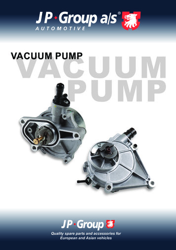
Medical Lubricated Vacuum3A.0 Start Up - TotalAlert Embedded ControlsCAUTION: Vibration during shipment andinstallation can loosen electrical terminals, fuseinserts, and mechanical connections. Tighten asnecessary. Check the electrical cabinet for any brokencomponents. Check that all motor starter connections aretight and that there are no loose objects suchas terminal lugs, screws, nuts, etc., in thecabinet.Check all voltages supplied to the LifeLine systemto ensure they are the required value and phasesneeded by the control panel.Apply power to the system and turn the disconnectswitches to “On”.3A.2 Initial Start-upCAUTION: Complete the prestart-up procedurebefore continuing with the initial start-upprocedureWARNING:To prevent electrical shock, ensure thatALL electrical power to the system is OFF,including the disconnect switches. Thefacility’s supply circuit breaker shouldalso be locked out.Manual OverrideSwitchO - On ManualX - OffA - Automatic3A.2.1 LubricationFigure 3A.1 Unit PCB Override SwitchThe pumps are oil lubricated. The lubricatingoil can be put into the pump at the oil filler portof the oil separator housing, observing the “MAX”and “MIN” position at the oil level sight glass. (Forrecommended oil type, refer to Section 6.1.) Afterfilling, make sure the oil filler port is closed.Prior to actual operation, the pumps must bechecked for correct rotation.All LifeLine lubricated vacuum pumps are shippedwith the required amount of oil for start-up. Thesystems are shipped with separate oil containers,which must be added before start-up.3A.2.2 Pump RotationInside the control panel, make sure that all unitprinted circuit boards are set to the manualoverride “Off” position. This is indicated by themiddle position “X” on the three-position slidingswitch as shown in Figure 3.1.4107 9000 96.04Inside the control cabinet, switch one of the unitprinted circuit boards from the manual override“Off” position to the bottom position, the default“Automatic” mode. Make sure the Pump Mode onthe Unit touchscreens are in the Off position, seeFigures 3.2 and 3.3. (See Figure A.15 for completelist of Screen Toolbar Descriptions).Check for correct direction of rotation of each pumpby pressing the “Rotation” button on touchscreendisplay (found in the Service section of the Unittouchscreens) and observing rotation. See Figure3.4. The Pump Mode for each compressor mustbe in the Off Position for the Rotation to function.3A-2
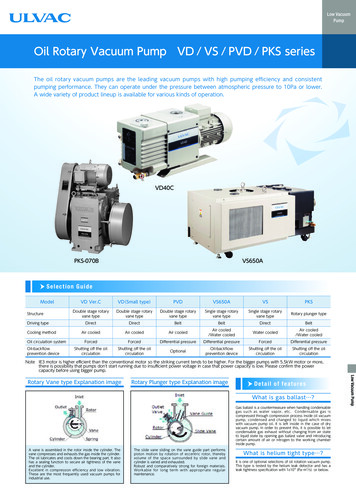
Medical Lubricated Vacuum3A.0 Start Up - TotalAlert Embedded ControlsMain ScreenUnit Screen # 1Unit Screen # 2Proximity SensorPower ON LightAlarm BuzzerFigure 3A.2 Touchscreen ControlsBy observing the cooling fan of the motor, you candetermine the rotation of the pump. After pressingthe “Rotation” button on the touchscreen, thereis a 5 second delay before the pump will start fora brief amount of time. Pump rotation should becounterclockwise when looking at the rear of themotor. Directional arrows are located on eachpump.If the pumps are rotating in the wrong direction,rotation can be reversed by switching any twomain power leads to the panel. Correct rotationshould be confirmed in the previous manner.Figure 3A.3 Unit Screen - Off PositionWARNING:Do not allow the vacuum pump torun backwards.Repeat the process of switching the Unit printedcircuit boards from the manual override “Off”position to the default “Automatic” position andtesting rotation.Figure 3A.4 Unit Screen - Service: Rotation3A-34107 9000 96.04
Medical Lubricated Vacuum3A.0 Start Up - TotalAlert Embedded Controls3A.3 Initial OperationStart each pump by pressing “Automatic” on thetouchscreen. See Figure 3.5.Figure 3A.5 Unit Screen - Automatic ModeWARNING:Pumps that have reached operatingtemperature may have a high surfacetemperature on the top of the exhaustmuffler.DO NOT TOUCH!Run the pump for two minutes in the correctrotation. Stop the pump and top off the oil levelutilizing the oil filler port to the correct level asshown in the sight glass. DO NOT OPEN THEFILLER PORT WHILE THE PUMP IS RUNNING.After testing each pump, if everything appearsnormal, put each pump into the “Automatic”mode and allow each pump to run until vacuumbuilds. Check for any leaks in the piping. Repairleaks, if needed.4107 9000 96.043A-4
Medical Lubricated Vacuum3B.0 Start Up - Basic ControlsNote: This section applicable to LubricatedRotary Vane Medical Vacuum Systems with theBasic control system.3B.1 Prestart-upshould be approximately 70 F (21.1 C) with aminimum ambient temperature of 40 F (4.4 C)and a maximum ambient temperature of 105 F(40 C). Check the intake piping for proper size andconnection to the vacuum modules. Check all piping system joints that might havecome loose during shipment and installationto ensure they are tight. Check the air receiver, controls, and pumps fordamage. Check the drain valve on the air receiver.WARNING: Prior to putting the LifeLine LubricatedRotary Vane Medical Vacuum systeminto use, the medical facility must have aCertifier perform all installation tests asspecified in NFPA 99. The medical facilityis also responsible for ensuring that theMedical Vacuum meets the minimumrequirements for Medical Vacuum asspecified in NFPA 99.Check all valves for full open and full closetravel. Ensure that the system’s valves arepositioned for proper operation. (Refer tolabeling on valve handles) Remove all packing material from theunit. Check the electrical connections to the controlcabinet. Verify electrical service. Before starting thesystem, check to see that voltage, amperage,and wire size are appropriate.The contractor should notify BeaconMedæstwo weeks prior to start-up date to schedule anappointment for an authorized technician toreview the installation prior to start-up.CAUTION: Failure to install the unit properly andhave an authorized technician from BeaconMedæsstart-up the system can void the manufacturer’swarranties.Prestart-up and start-up procedures should beperformed for a new installation or when majormaintenance has been performed.WARNING:CAUTION: Electrical service must be as specifiedor damage to equipment may occur.Have more than one person on hand duringprestart-up and start-up procedures toensure safety and to facilitate certainchecks.WARNING:To prevent electrical shock, ensure thatALL electrical power to the system is OFF,including the disconnect switches andAutomatic-Off-Manual switches on thecontrol panel. The facility’s supply circuitbreaker should also be locked out.The main power source to the control panel shouldbe OFF for the duration of the visual inspection.Ensure that the equipment is installed on a solidlevel surface. Walk around the system to ensure thatthere is enough clearance on all sides to performoperational checks/actions and maintenance. Thetemperature of the area containing the modules Open the electrical cabinet by loosening thefasteners on the front.3B-14107 9000 96.04
Medical Lubricated Vacuum3B.0 Start
Lubricated Rotary Vane Medical Vacuum System Part number 4107 9000 96 Revision 04 August 27, 2018. Part number Revision ugust , Installation, Operation and Maintenance Manual 1.5 - 25 Hp Medical Lubricated Rotary Vane Vacuum System (Not intended for use on dedicated WAGD applications as per NFPA 99 - 2005 edition) . 80 MHz to 2,5 GHz 3 Vrms .