Transcription
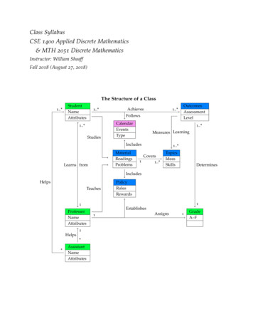
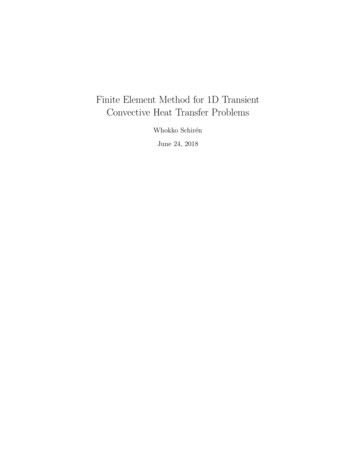
Historical Constructions, P.B. Lourenço, P. Roca (Eds.), Guimarães, 2001719Discrete element analysis on the Sardinian “Nuraghe”Giulio Mirabella RobertiMediterranean University of Reggio Calabria, Reggio Calabria, ItalyOlga SpinaArchitect, graduate at Politecnico di Milano, Milan, ItalyABSTRACT: The “Nuraghe” in Sardinia are very fascinating architectural documents of theancient pre-roman civilisations of the Mediterranean Sea, that still need to be deeply studied andexplained. Some important problems arise regarding the conservation of these architecturesfrom the past, that are so spread over the Sardinian Island. A deeper knowledge of the materialsand of the overall structural behaviour is strongly needed to assess the stability and to chooseappropriate methods for restoration. Starting from a survey on the Nuraghe “Santu Antine” inTorralba (SS), a numerical analysis was performed on the stability of the dome, consideringdifferent hypothesis on the construction process. In order to the take into account the realcharacteristic of the dry stone masonry, made by big and stiff blocks laying together, a discreteelement approach was adopted, able to model the discontinuities, that are the relevant mechaniccharacteristic of this masonry. A particular approach was needed to simulate in 2D the thicknessvariation of the dome slice studied, neglecting the stabilising contribution of adjacent slices. Theresults are encouraging, and demonstrate the possibility of constructing such domes without theaid of centring, if the right shape is controlled.1 INTRODUCTIONIt is well known that the Mediterranean Sea was the scene of a large network of commercial andcultural exchanges largely before the historic age. The peoples living on his shores found in theisland of the Mediterranean, as well as in the Italian and Greek peninsulas, the natural bases oftheir travel through the sea. So important pre-historic civilisations arise also in the SardinianIsland, and have very impressive connections with other civilisations of the Mediterranean Sea.One of the most impressive is the Nuraghiccivilisation, that receive the name from his mostimportant and diffused architecture, and lasts (withdifferent fortunes) from the Ancient Bronze Age (18thcent. BC) until the roman conquest (238 BC) (seeAtzeni et al. 1990).More than 8000 "Nuraghe" are spread in the island,reaching a density of about one per square km insome zones, depending mainly on the quality andavailability of the stone. They are more or lesspreserved in their volumetric presence, but alwayswell recognisable almost in plan. The shape can varyfrom the simplest ones, in which only the Tholos ispresent, to the more complex, polylobate plan, alsowith external curtain walls. In any case, these massiveFigure1: The tholos of the Nuraghestone monuments are characterised by a tower in theMadrone, Silanus (NU)shape of a truncated cone, with an internal main room
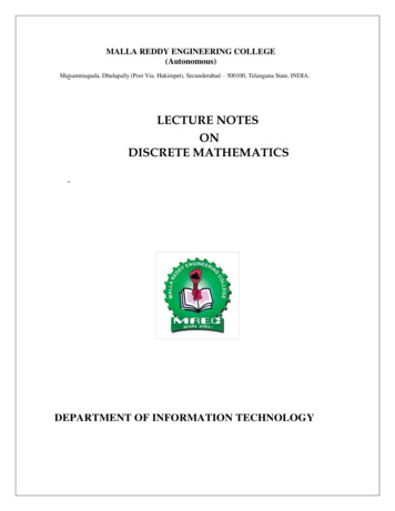
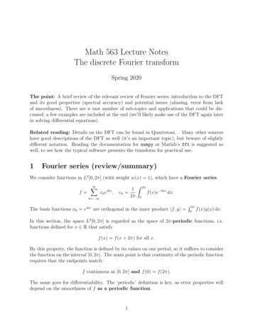
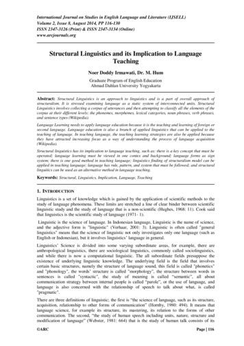
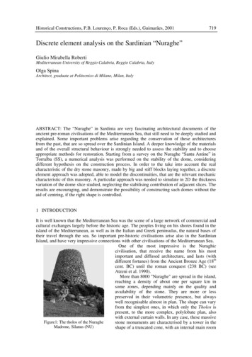
720Historical Constructionscovered by a tholos dome that give the name to the whole tower (Fig. 1).Figure 2: The Tholos dome in Nuraghe Santu Antine(view from the bottom to the top)Figure 3: The stone vault of a corridorThe tholos construction is made by layers of stones disposed in concentric rings of decreasingdiameter, overhanging from the previous ring, from the bottom to the top (Fig.2). A similarconstruction system was adopted for covering also long corridors forming a sort of corbelledbarrel vault (Fig. 3).There is a lot of examples of tholos domes in the pre-classic civilisations of theMediterranean sea, like the well known “Atreus Thesaurus” in Mycenae, that can be taken as aproof of the connections among these ancient peoples; some of them survive also in the habitsof the island inhabitants in the past centuries.Despite a vast literature on the subject, the secret of the use of these massive stone buildingsis not completely disclosed. In fact, they have been interpreted in many different ways, puttingin evidence some particular aspect of the construction: they have been explained in turn asfuneral monuments, or generally religious buildings, or as utility buildings, like grain silos oreven bronze furnaces, or more often as military fortresses, but none of these interpretationsalone is completely satisfactory. Maybe they were many different things together, but a definiteproof is hard to be found.In any case, these monuments are still the witness of the strength and the power of the peoplewho build them, but they exhibit in the same time the toughness of stone buildings that lastoften more than 30 centuries and in the same time the weakness and brittleness of anarchaeological site, giving rise to very delicate problems in their conservation.2 THE NURAGHE SANTU ANTINEOne the most interesting and well-preserved example of nuraghe is in the territory of Torralba(SS). Recent archaeological excavations dated the monument before 1500 BC, although manyauthors supposed almost two different phases in the construction.During a survey on behalf of the Soprintendenza Archeolgica (Archaeological HeritageOffice) of Northern Sardinia, we take the opportunity to develop a graduate thesis on theconservation problems and on the structural analysis of this monument (Spina 2000).The Nuraghe has a tri-lobated plan, with the main central tower on three levels (obtained bysuperimposed tholos domes) and the minor tholos on the three rounded corners, connected by anexternal continuous wall, where two covered corridors are running. An inner yard is delimitedby the southern wall, where the main entrance opens, and the central tholos. The overalldimensions are nearly 39 m in width and 17.5 m in height (Fig. 4).
G. M. Roberti and O. Spina721The external walls are made by big regular blocks of basalt, more refined in the upper layers,with a light slope from the vertical.Figure 4: A bird’s eye view of the Nuraghe Santu AntineThe masonry of the main tholos shows very regular ashlars, cut to fit the curvature of thewall. The main room has a diameter of 5.25 m and the vault is made by 21 layers of stones,reaching an height of 7.9 m. The blocks decrease in size from the bottom to the top, but aremuch less regular than the exterior ones. A surrounding corridor is connected to the room byfour openings, leading also to the helices-shaped staircase running inside the thickness of thewall, reaching the upper levels. The second level has a circular room of 4.5 m in diameter and5.3 m in height; the upper one has been destroyed in 1866 for building a public fountain inTorralba, and only 5 layers of stones are still in site (Contu,1993).3 NUMERICAL ANALYSISThe aim of a numerical analysis on a so ancient monument is on the one hand the safetyassessment and the stability verification of the building itself, in order to receive someguidelines for the conservation and to avoid unnecessary interventions; on the other hand, abetter understanding of the rules governing the construction, trying to contribute to thediscovering of his secrets.The first problem in modelling this masonry arises in the definition of their geometrical andmechanical characteristics. The modelling of such structures as continuous media is far frombeing a good representation of their real behaviour, due to the great number of discontinuities.In most of the cases, the presence of mortar in the joints is so rare that masonry can beconsidered as dry walls. Moreover, the difficulties of cutting regular blocks from hard stonesgave origin to quite irregular dispositions.In any case, the intrinsic nature of these construction require the use of an approach able totake into account the strong discontinuities that are present in the stone walls, so that a discreteelement approach was preferred to a more classic finite element one. In fact, although both rockmasses and masonry structures can be modelled in a discrete manner using FEM and BEMapproaches, the description of discontinuities is usually difficult and there are often restrictionsto the degree of deformation permitted. On the other hand, DEM are generally more tailored forproblems in which large deformations and displacements are involved, and many materialdiscontinuities, placing a special emphasis on how contact is handled.
722Historical Constructions3.1 Distinct Element CodeThe name “discrete element method” applies to a computer program only if: (a) it allows finitedisplacements and rotations of discrete bodies, including complete detachment; (b) it recognisesnew contacts automatically as the calculation progresses.The term “distinct element method” was coined by Cundall and Strack (1979) to refer to theparticular discrete element scheme that uses: (i) deformable contacts and (ii) an explicit, timedomain solution of the original equations of motion.In the followings, a particular commercial code originally formulated by Cundall (1971) andfurther developed in Lemos et al. (1985) was applied to the stone masonry of the Nuraghe.The Universal Distinct Element Code (UDEC) is a 2-D numerical program based on thedistinct element method for discontinuum modelling. UDEC simulates the response ofdiscontinuous media subjected to either static or dynamic loading.The discontinuous medium is represented as an assemblage of discrete blocks. Thediscontinuities are treated as boundary conditions between blocks; large displacements alongdiscontinuities and rotations of blocks are allowed. Individual blocks behave as either rigid ordeformable material. Deformable blocks are subdivided into a mesh of finite-differenceelements, and each element responds according to a prescribed linear or non-linear stress-strainlaw. The relative motion of the discontinuities is also governed by linear or non-linear forcedisplacement relations for movement in both the normal and shear directions.3.2 Calculation basisIn the distinct element method, a rock mass is represented as an assembly of discrete blocks.Joints are viewed as interfaces between distinct bodies (i.e., the discontinuity is treated as aboundary condition). The contact forces and displacements at the interfaces of a stressedassembly of blocks are found through a series of calculations that trace the movements of theblocks. Movements result from the propagation through the block system of disturbances causedby applied loads or body forces. This is a dynamic process in which the speed of propagationdepends on the physical properties of the discrete system.The dynamic behaviour is represented numerically by a timestepping algorithm in which thesize of the timestep is limited by the assumption that velocities and accelerations are constantwithin the timestep. The distinct element method is based on the concept that the timestep issufficiently small that, during a single step, disturbances cannot propagate between one discreteelement and its immediate neighbours. This corresponds to the fact that there is a limited speedat which information can be transmitted in any physical medium.The calculations performed in the distinct element method alternate between application of aforce-displacement law at all contacts and Newton’s second law at all blocks. The forcedisplacement law is used to find contact forces from known (and fixed) displacements.Newton’s second law gives the motion of the blocks resulting from the known (and fixed)forces acting on them. If the blocks are deformable, motion is calculated at the gridpoints of thetriangular finite-strain elements within the blocks. Then, the application of the block materialconstitutive relations gives new stresses within the elements.To better explain how discretization proceeds, start considering the one-dimensional motionof a single mass acted on by a varying force, F(t). Newton’s second law of motion can bewritten in the form:du& Fdt m(1)where u& is the velocity and m is the mass. Using a central finite difference scheme, velocityis calculated as:du& u& ( t t 2) u& (t t 2)dt t(2)so that, substituting left hand side of Eq. (1) and rearranging terms, the new velocity can becalculated as:
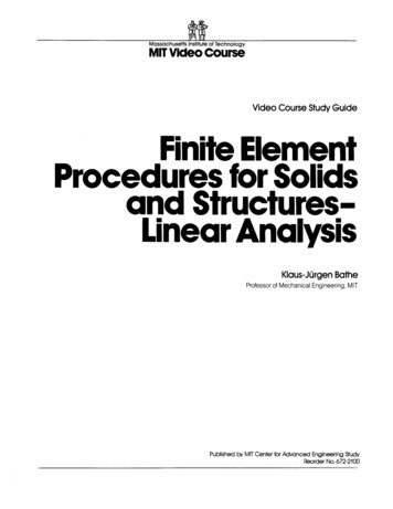
G. M. Roberti and O. Spina(t )u& ( t t 2) u& ( t t 2) F tm723(3)With velocities stored at the half-timestep point, it is possible to express displacement asu ( t t ) u (t ) u& ( t t 2) t(4)so that new contact forces can be calculated based on the updated position and a new timestepcan start.4 SELECTED VERIFICATIONSSome selected problems were chosen in order to verify the possibility of analysing thesemassive stone buildings with modern calculation techniques, and to compare the numericalprediction with the physical evidence.The first problem is the stability analysis of a stone wall with openings, that gave theopportunity of testing some general features of the code, like the use of deformable vs. rigidblocks, the choice of material properties and of the appropriate time step. A particular aspectwas investigated, that is the capability of reproducing also some details of stress concentrationsinside the blocks, giving rise to the cracking behaviour of the stones.The second problem afforded, structurally more complex, was the stability analysis of theTholos dome, taking into account in particular the different phases of the construction process,simulated with modifications both of the model and of the loads.4.1 The north-east wallA photographic survey of the north-east wall was used as a basis for drawing a wire-framerepresentation of the stones forming the blocky structure (Figs. 5,6) that also constitutes the 2 Dmodel studied in the analysis, loaded by the dead weight of the same stones.Figure 5: Photographic survey of the north-east wall.
724Historical ConstructionsTable 1: Material propertiesstone (basalt)density2100 kg/m3compression strength17 MPatension strength1.7 MPabulk modulus27.77 GPashear modulus20.83 GPasoildensity1600 kg/m3bulk modulus4.5 GPashear modulus4.0 GPajointsfriction angle30 normal stiffness50 GN/m3tangential stiffness20 GN/m3Figure 6: Cracked configuration of the linteland velocity plot at the end of the analysis.Figure 7: Wire-frame model of the north-east wall.In the analysis, three different approaches were adopted: in the first, the blocks wereconsidered perfectly rigid; in the second, all the blocks were assumed deformable; in the third,only selected blocks were assumed deformable. The soil beneath the wall was always assumeddeformable, in order to allow some movement of the blocks. The mechanical properties of thematerials (taken form the literature) are reported in Table 1.The two parts of the cracked lintel were considered first stuck together, assigning very hightension strength to the joint representing the crack; then the strength was reduced until the jointopens under the gravity loads.The crack open for a tension strength of 21.4 MPa for the first model and 20.7 for the second.The third model (partially deformable, to reduce computational time) gives an intermediateresult of 21 MPa. These values are too high, compared to the supposed properties of the stone,indicating that the lintel can not stay integer in the actual situation of the wall, or else that thiskind of analysis is not enough accurate at the stress level to catch the phenomenon of crackpropagation. In any case, in the cracked configuration the lintel (Fig. 7) results stable, excludingthe necessity of a structural intervention.4.2 The Tholos DomePerhaps the most appealing structural problem of the “Nuraghe” is the study of the tholos dome.Many authors suggest that the tholos construction can exploit the ring effect that the stonesexert one against the other on the same layer when they are trying to fall inside (Cavenagh &
G. M. Roberti and O. Spina725Lauxton), although this effect has been somewhat exaggerated. In any case, it is quite difficultto imagine the system adopted by the ancient builders to erect these monuments. The cantilevereffect, if cleverly controlled, can allow to form the dome shape without the aid of scaffolds?The first problem in the model was the simulation of the varying thickness of the dome in a2-D model, also neglecting the contribution of the ring effect, as pointed out already thePoleni’s study of on the St. Peter’s dome (Fig. 8). The solution chosen was to assign differentmass densities to the blocks, in proportion to the distance of their gravity centre from the axis ofthe dome (and so to the thickness of the dome slice in this point).Many other aspects are to be considered: only the inner geometrical shape of the dome can bereproduced, being unknown the deepness of the stones; the same problem arise in the thicknessof the external leaf and in the presence of the backfill. So that the geometrical model can beonly a trial reconstruction of the cross-section, based on the examination of similar tholospartially collapsed, with a much more regular blocky structure represented in Fig. 9 (where thebackfill is made by smaller deformable blocks of reduced density).The first model analysed shown that the dome slice remain stable when the gravity load isapplied, without the help of the ring effect (Fig. 9). This result can be confirmed by manyexamples of tholos domes partially collapsed and still standing.Figure 8: Half an arch compared to a dome sector, from Poleni (1748)Figure 9: Contact forces for the dome slice aftergravity stabilisation.Figure10: Collapse mechanism for the model ofbarrel vault with friction angle 3 Another aspect of the problem is the effect of the friction between blocks. For the dome slice,decreasing the value of friction angle from the nominal value of 30 to a null value do notproduce any remarkable effect on the stabilisation; this is not completely true for a barrel vault
726Historical Constructionsof the same cross section, that reach the collapse for a friction angle of 3 (in this test the blocksof the same material have constant density).Finally, the superposition of the blocksduring the construction was simulated,activating one layer at time (starting fromthe 10th) and waiting until completestabilisation under gravity force before theactivation of the next layer. The history ofthe “unbalanced force” (that include inertiaforces) during the analysis is reported inFig. 11. The contact closure vary during theanalysis as shown in Fig 12 and the finalconfiguration is lightly different from theone in Fig. 9, but the dome is still stable,provided that the backfill and the externalwall are built together with the internalFigure11: Unbalanced forces during the layer’sdome.superpositionFigure 12: Contact stresses during construction phasesFigure 13: Velocity vectors and contact closures at collapse for the dome built without backfill.The importance of the backfill is demonstrated by another simulation, where a dome sectorwas analysed together with its symmetrical counterpart in the absence of the backing structure.If the ring effect is neglected, (or not effective due to the irregular cut of the blocks) the domecollapse, also with high friction angle values, as shown in Fig.13. The same experimentrepeated increasing the dimensions of the blocks of the upper layers (from 10th to 21st) gave
G. M. Roberti and O. Spina727similar results, suggesting that the stability is not governed by the shape of the blocks but by thetotal load of the layers, and the external wall give a fundamental contribution to the stability.5 CONCLUSIONSAlthough limited to a 2-D analysis (mainly for economical reason, because a 3-D code is on themarket) the Distinct Element Method seems to be an effective tool for the stability analysis ofthese ancient construction, focusing more on block stability and equilibrium than on accuratestress determination inside the blocks. This aspect can be critical on the study of block crackingdue to changed boundary conditions, but much work is needed on this subject.Some general consideration can be drawn on the stability of the tholos construction:§ a sector of the tholos dome can stand up alone, provided that the section of the wall iscomplete, including the external wall and the filling;§ the out-of-plane ring effect can be helpful, but is not necessary to the stability;§ the friction plays a role only in the case of vault of constant thickness (barrel vault crosssection) although a very small friction angle is sufficient to ensure the stability.Further research will deal with the problem of cracking detection and with a better simulationof the tri-dimensional effects in the dome.ACKNOWLEDGEMENTSThe encouragement of Prof. Luigia Binda, who supervised the thesis at the Politecnico diMilano, is gratefully acknowledged, as well as the helpful contributions of Drs Susanna Baficoand Sergio Lanza to the knowledge of the Nuraghe; and finally the SoprintendenzaArcheologica of Sassari and Nuoro that gave the possibility of studying this monument.REFERENCESAtzeni, E. et al., 1990. Ichnussa. La Sardegna dalle origini all’età classica. Milano: Garzanti-Scheiwiller.Cavanagh, W.G. and Laxton, R.R. 1987. An investigation into construction of Sardinian nuraghi,reprinted from the papers of the British School of Archeology at Rome, vol. LV.Contu, E. 1993. Il Nuraghe Santu Antine, in Sardegna Archeologica. Guide e itinerari, Sassari: Delfino.Cundall, P.A. 1971. A computer model for simulating progressive large scale movements in blocky rocksystems, Proc. of the Symp. of the International Society of Rock Mechanics (Nancy, France, 1971),vol. 1, paper no. II-8.Cundall, P.A., Strack, O.D.L., 1979. A Discrete Numerical Model for Granular Assemblies,Géotechnique, 29, pp.47-65.Itasca Consulting Group, 1993. UDEC: Universal Distinct Element Code - Theory and background,version 1.7, Minneapolis, MN.Lemos, J.V., Hart R.D. and Cundall, P.A. 1985. A generalized distinct element program for modelingjointed rock mass, in Proc. Int. Symp. on Fundamentals of rock joints (Bjorkliden, 1985), pp. 335-343.Luleå, Sweden: Centek.Poleni, G. 1748. Memorie istoriche della gran cupola del tempio Vaticano e de’ danni di essa, e de’ristoramenti loro, Padua, Italy.Spina, O. 2000. The Nuraghe Santu Antine: structural analysis and conservation problems (in Italian).Graduate Thesis, Faculty of Architecture, Politecnico di Milano, Milan, Italy.
728Historical Constructions
cent. BC) until the roman conquest (238 BC) (see Atzeni et al. 1990). More than 8000 "Nuraghe" are spread in the island, reaching a density of about one per square km in some zones, depending mainly on the quality and availability of the stone. They are more or less preserved in their volumetric presence, but always well recognisable almost in .