Transcription
NI Vision for LabVIEW BasicsJune 2008, 371007D-01NI Vision for LabVIEW—a part of the NI Vision Development Module—isa library of LabVIEW VIs you can use to create machine vision andscientific imaging applications. This help file guides you through tasksbeginning with setting up your imaging system to taking measurements.This help file also describes how to create a real-time application usingNI Vision with the LabVIEW Real-Time Module.To comment on National Instruments documentation, refer to the NationalInstruments Web site. 2005–2008 National Instruments Corporation. All rights reserved.
Introduction to NI VisionThis section describes the NI Vision for LabVIEW software, outlines theNI Vision palette organization, and lists the steps for developing amachine vision application.Note Refer to the Readme.html file for information about thesystem requirements and installation procedures for NI Vision.
NI Vision Control PaletteThe Vision controls palette is available from the top level of the LabVIEWControls palette. The Vision control palette contains the followingelements:IMAQ Image.ctl—This control is the type definition that describesthe image data type. You can use this control to represent theimage data type on the front panel of a VI. For example, use thiscontrol as an input or output of a subVI so that a calling VI canpass an image to the subVI.Image Display—Use this control to display your images directly onthe LabVIEW. You also can use this control to create regions ofinterest (ROIs). Both Classic and 3D versions of the Image Displaycontrol are available.IMAQ Vision controls—Use these controls to get the functionalityof corresponding NI Vision VI controls directly into your own VIs.Machine Vision controls—Use these controls to get thefunctionality of corresponding Machine Vision VI controls directlyinto your own VIs.
NI Vision Function PalettesNI Vision for LabVIEW is organized into three main function palettes:Vision Utilities, Image Processing, and Machine Vision. This sectiondescribes these palettes and their subpalettes.Note This document references many VIs from the NI Visionfunction palette. If you have difficulty finding a VI, use the searchcapability of the LabVIEW VI browser.
Vision UtilitiesVision Utilities functions allow you to manipulate and display images inNI Vision.Image Management—A group of VIs that manage images. Usethese VIs to create and dispose images, set and read attributes ofan image such as its size and offset, and copy one image toanother. You also can use some of the advanced VIs to define theborder region of an image and access the pointer to the imagedata.Files—A group of VIs that read images from files, write images tofiles in different file formats, and get information about the imagecontained in a file.External Display—A group of VIs that control the display of imagesin external image windows. Use these VIs to complete thefollowing tasks:Get and set window attributes, such as size, position, andzoom factorAssign color palettes to image windowsSet up and use image browsersSet up and use different drawing tools to interactively selectROIs on image windowsDetect draw eventsRetrieve information about ROIs drawn on the imagewindowRegion of Interest—A group of VIs that manage ROIs. Use theseVIs to programmatically define ROIs and convert ROIs to and fromimage masks.Image Manipulation—A group of VIs that modify the spatial contentof images. Use these VIs to resample an image, extract parts of animage, and rotate, shift, and unwrap images. This subpalette alsocontains VIs that copy images to and from the clipboard.Pixel Manipulation—A group of VIs that read and modify individualpixels in an image. Use these VIs to read and set pixel values in animage or along a row or column in an image, fill the pixels in animage with a particular value, and convert an image to and from a
2D LabVIEW array.Overlay—A group of VIs that overlay graphics on an imagedisplay environment without altering the pixel values of theimage. Use these VIs to overlay the results of your inspectionapplication onto the images you inspect.Calibration—A group of VIs that spatially calibrate an image to takeaccurate, real-world measurements regardless of cameraperspective or lens distortion. Use these VIs to set a simplecalibration or to let NI Vision automatically learn the calibrationdata from a grid image. Then use the VIs to convert pixelcoordinates to real-world coordinates for simple measurements.Color Utilities—A group of VIs that access data from color images.Use these VIs to extract different color planes from an image,replace the planes of a color image with new data, convert a colorimage to and from a 2D array, read and set pixel values in a colorimage, and convert pixel values from one color space to another.Vision RT—A group of VIs that provide functionality for using NIVision with the LabVIEW Real-Time (RT) Module. Use these VIs todisplay images to Video Out on your RT system, to control thecompression setting for sending images over the network, and totime bound your processing VIs on your RT system.
Image ProcessingUse the Image Processing functions to analyze, filter, and processimages in NI Vision.Processing—A group of VIs that process grayscale and binaryimages. Use these VIs to convert a grayscale image into a binaryimage using different thresholding techniques. You also can usethese VIs to transform images using predefined or custom lookuptables, apply a watershed transform, change the contrastinformation in the image, and invert the values in an image.Filters—A group of VIs that filter an image to enhance theinformation in the image. Use these VIs to smooth an image,remove noise, and highlight or enhance edges in the image. Youcan use a predefined convolution kernel or create customconvolution kernels.Morphology—A group of VIs that perform morphological operationson an image. Some of these VIs perform basic morphologicaloperations, such as dilation and erosion, on grayscale and binaryimages. Other VIs improve the quality of binary images by fillingholes in particles, removing particles that touch the image border,removing small particles, and removing unwanted particles basedon different shape characteristics of the particle. Another set of VIsin this subpalette separate touching particles, find the skeleton ofparticles, and detect circular particles.Analysis—A group of VIs that analyze the content of grayscale andbinary images. Use these VIs to compute the histograminformation and grayscale statistics of an image, retrieve pixelinformation and statistics along any one-dimensional profile in animage, and detect and measure particles in binary images.Color Processing—A group of VIs that analyze and process colorimages. Use these VIs to compute the histogram of color images;apply lookup tables to color images; change the brightness,contrast, and gamma information associated with a color image;and threshold a color image. Some of these VIs also compare thecolor information in different images or different regions in animage using a color matching process.Operators—A group of VIs that perform basic arithmetic and logical
operations on images. Use some of these VIs to add, subtract,multiply, and divide an image with other images or constants. Useother VIs in this subpalette to apply logical operations—such asAND/NAND, OR/NOR, XOR/XNOR—and make pixel comparisonsbetween an image and other images or a constant. In addition, oneVI in this subpalette allows you to select regions in an image toprocess using a masking operation.Frequency Domain—A group of VIs that analyze and processimages in the frequency domain. Use these VIs to convert animage from the spatial domain to the frequency domain using atwo-dimensional Fast Fourier Transform (FFT) and convert fromthe frequency domain to the spatial domain using the inverse FFT.These VIs also extract the magnitude, phase, real, and imaginaryplanes of the complex image. In addition, these VIs allow you toconvert complex images into complex 2D arrays and back. Also inthis subpalette are VIs that perform basic arithmetic operations—such as addition, subtraction, multiplication, and division—betweena complex image and other images or a constant. Lastly, some ofthese VIs allow you to filter images in the frequency domain.
Machine VisionThe Machine Vision functions are high-level VIs that simplify commonmachine vision tasks.Select Region of Interest—A group of VIs that allow you to selecta ROI tool, draw specific ROIs in the image window, and returninformation about ROIs with very little programming.Coordinate System—A group of VIs that find a coordinate systemassociated with an object in an image. Use these VIs to find thecoordinate system using either edge detection or pattern matching.You can then use this coordinate system to take measurementsfrom other Machine Vision VIs.Count and Measure Objects—A VI that thresholds an image toisolate objects from the background and then finds and measurescharacteristics of the objects. This VI also can ignore unwantedobjects in the image when making measurements.Measure Intensities—A group of VIs that measure the intensity ofa pixel at a point or the statistics of pixel intensities along a line orrectangular region in an image.Measure Distances—A group of VIs that measure distances,such as the minimum and maximum horizontal distance betweentwo vertically oriented edges or the minimum and maximumvertical distance between two horizontally oriented edges.Locate Edges—A group of VIs that locate vertical, horizontal, andcircular edges.Find Patterns—A VI that learns and searches for a pattern in animage.Searching and Matching—A group of VIs that create and searchfor patterns in grayscale and color images. This subpalette alsocontains a VI to search for objects with predefined shapes in binaryimages.Caliper—A group of VIs that find edges along different profiles inthe image. Use these VIs to find edges along a line, a set ofparallel lines defined inside a rectangular region (rake), a set ofparallel concentric lines defined inside an annular region(concentric rake), or a set of radial lines defined inside an annularregion (spoke). You also can use these VIs to find pairs of edges in
the image that satisfy certain criteria.Analytic Geometry—A group of VIs that perform analytic geometrycomputations on a set of points in an image. Use these VIs to fitlines, circles, and ellipses to a set of points in the image; computethe area of a polygon represented by a set of points; measuredistances between points; and find angles between linesrepresented by points. VIs in this subpalette also performcomputations, such as finding the intersection point of two linesand finding the line bisecting the angle formed by two lines.OCR—A group of VIs that perform optical character recognitionand verification in a region of the image.Classification—A group of VIs that classify binary objectsaccording to their shape or any user-defined feature vector.Instrument Readers—A group of VIs that accelerate thedevelopment of applications that require reading from sevensegment displays, meters, gauges, 1D barcodes, or 2D codes.Inspection—A group of VIs that compare images to a goldentemplate image.
Vision ExpressUse the Vision Express VIs to quickly develop common image acquisitionand processing applications.Vision Acquisition—An Express VI to easily configureacquisitions from analog, digital, Camera Link, IEEE 1394, andGigE Vision cameras.Note You must have NI Vision Acquisition Softwareinstalled to access the Vision Acquisition Express VI.Vision Assistant—An Express VI that allows you to use NI VisionAssistant from within the LabVIEW environment to performcommon image processing tasks.
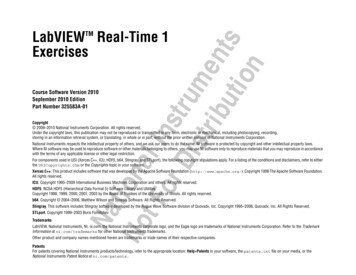
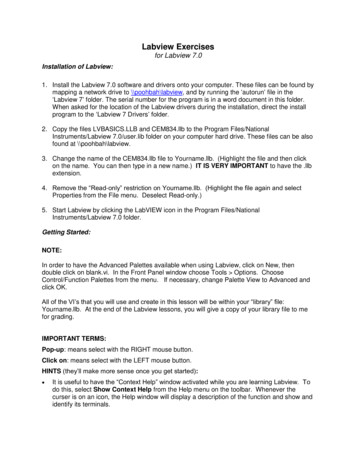
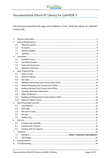
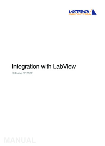
How to Create NI Vision ApplicationsThe following figures illustrate the steps for creating an application withNI Vision. the first figure describes the general steps to designing an NIVision application. Items 2 and 3 in the last step in the first figure areexpanded upon in the second figure. You can use a combination of theitems in the last step to create your NI Vision application.Refer to the section corresponding to each figure item name for moreinformation about the item.Note Diagram items enclosed with dashed lines are optionalsteps.
Note Diagram items enclosed with dashed lines are optionalsteps.
Getting Measurement-Ready ImagesThis section describes how to set up your imaging system, acquire anddisplay an image, analyze the image, and prepare the image foradditional processing.
Set Up Your Imaging SystemBefore you acquire, analyze, and process images, you must set up yourimaging system. The manner in which you set up your system dependson your imaging environment and the type of analysis and processingyou need to do. Your imaging system should produce images with highenough quality so that you can extract the information you need from theimages.Complete the following steps to set up your imaging system.1. Determine the type of equipment you need given spaceconstraints and the size of the object you need to inspect. Refer toChapter 3, System Setup and Calibration, of the NI VisionConcepts Manual for more information.a. Make sure your camera sensor is large enough to satisfyyour minimum resolution requirement.b. Make sure your lens has a depth of field high enough tokeep all of your objects in focus regardless of theirdistance from the lens. Also, make sure your lens has afocal length that meets your needs.c. Make sure your lighting provides enough contrast betweenthe object under inspection and the background for you toextract the information you need from the image.2. Position your camera so that it is perpendicular to the objectunder inspection. If your camera acquires images of the objectfrom an angle, perspective errors occur. Even though you cancompensate for these errors with software, National Instrumentsrecommends that you use a perpendicular inspection angle toobtain the most accurate results.3. Select an image acquisition device that meets your needs.National Instruments offers several image acquisition devices,such as analog color and monochrome devices as well as digitaldevices. Visit ni.com/vision for more information about NI imageacquisition devices.4. Configure the driver software for your image acquisition device.If you have an NI image acquisition device, configure your NIIMAQ or NI-IMAQdx driver software through Measurement&Automation Explorer (MAX). Open MAX by double-clicking the
Measurement & Automation icon on your desktop. Refer to theMeasurement & Automation Explorer Help for NI-IMAQ or theMeasurement & Automation Explorer for NI-IMAQdx Help formore information.
Calibrate Your Imaging SystemAfter you set up your imaging system, you may want to calibrate yoursystem to assign real-world coordinates to pixel coordinates andcompensate for perspective and nonlinear errors inherent in your imagingsystem.Perspective errors occur when your camera axis is not perpendicular tothe object under inspection. Nonlinear distortion may occur fromaberrations in the camera lens. Perspective errors and lens aberrationscause images to appear distorted. This distortion displaces information inan image, but it does not necessarily destroy the information in theimage.Use simple calibration if you only want to assign real-world coordinates topixel coordinates. Use perspective and nonlinear distortion calibration ifyou need to compensate for perspective errors and nonlinear lensdistortion.
Create an ImageUse the IMAQ Create VI to create an image reference. When you createan image, specify one of the following image data types:Grayscale (U8, default)—8-bit unsignedGrayscale (U16)—16-bit unsignedGrayscale (I16)—16-bit signedGrayscale (SGL)—Floating pointComplex (CSG)—64-bit complexRGB (U32)—32-bit RGBHSL (U32)—32-bit HSLRGB (U64)—64-bit RGBYou can create multiple images by executing IMAQ Create as manytimes as you want, but each image you create requires a unique name.Determine the number of required images through an analysis of yourintended application. Base your decision on different processing phasesand whether you need to keep the original image after each processingphase.Note If you plan to use filtering or particle analysis VIs on theimage, you must make sure to have an appropriate border size forthe image. The default border size is three pixels.When you create an image, NI Vision creates an internal image structureto hold properties of the image, such as its name and border size.However, no memory is allocated to store the image pixels at this time.NI Vision VIs automatically allocate the appropriate amount of memorywhen the image size is modified. For example, VIs that acquire orresample an image alter the image size so they allocate the appropriatememory space for the image pixels. The output of IMAQ Create is areference to the image structure. Supply this reference as an input to allsubsequent NI Vision functions.During development, you may want to examine the contents of yourimage at run time. You can use a LabVIEW image probe to view thecontents of your image during execution. To create a probe, right-click theimage wire and select Probe.Most VIs belonging to the NI Vision library require an input of one
or more image references. The number of image references a VI takesdepends on the image processing function and the type of image youwant to use.NI Vision VIs that analyze the image but do not modify the contentsrequire the input of only one image reference. VIs that process thecontents of images may require a reference to the source image(s) andto a destination image, or the VIs may have an optional destinationimage. If you do not provide a destination image, the VI modifies thesource image.At the end of your application, dispose of each image that you createdusing the IMAQ Dispose VI.
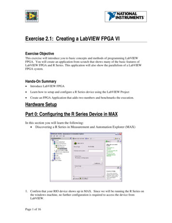
Input and Output CombinationsDepending on the type of function a VI performs, different combinationsof input and output are possible. You can use this flexibility to decidewhich image to process and where to store the resulting image. If nodestination image is wired, the source image is used and passed to thedestination output.The figures in the following sections show several VI connector panesused in NI Vision.Image AnalysisThe following connector pane applies only to VIs that analyze an imageand therefore do not modify either the size or contents of the image.Examples of these types of operations include particle analysis andhistogram calculations.Image MasksThe following connector pane introduces an Image Mask.The presence of an Image Mask input indicates that the processing oranalysis is dependent on the contents of another image: the ImageMask. The only pixels in Image that are processed are those whosecorresponding pixels in Image Mask are non-zero. If an Image Maskpixel is 0, the corresponding Image pixel is not changed.Note The image mask must be an 8-bit image for all NI Vision VIsexcept the IMAQ Quantify VI, which supports both 8-bit and 16-bitimage masks.If you want to apply a processing or analysis function to the entire image,do not connect the Image Mask input. Connecting the same image toboth inputs Image and Image Mask also gives the same effect asleaving the input Image Mask unconnected, except in this case theImage must be an 8-bit image.
Image FillingThe following connector pane applies to VIs performing an operation thatfills an image.Examples of this type of operation include reading a file, acquiring animage from an NI image acquisition device, or transforming a 2D arrayinto an image. This type of VI can modify the size of an image.Image ProcessingThe following connector pane applies to VIs that process an image.This connector is the most common type in NI Vision. The Image Srcinput receives the image to process. The Image Dst input can receiveeither another image or the original, depending on your goals. If twodifferent images are connected to the two inputs, the original Image Srcimage is not modified. As shown in the following diagrams, if theImage Dst and Image Src inputs receive the same image, or if nothing isconnected to Image Dst, the processed image is placed into the originalimage, and the original image data is lost.The Image Dst input is the image that receives the processing results.Depending on the functionality of the VI, this image can be either thesame or a different image type as that of the source image. Individual VIdescriptions include the type of image that can be connected to theImage inputs. The image connected to Image Dst is resized to thesource image size.Arithmetic and Logical OperationsThe following connector pane applies to VIs that perform arithmetic orlogical operations between two images.
Two source images exist for the destination image. You can perform anoperation between two images, A and B, and then either store the resultin another image, Image Dst, or in one of the two source images, A or B.In the latter case, you can consider the original data to be unnecessaryafter the processing has occurred. The following combinations arepossible in this pane.In the pane on the left, the three images are all different. Image Src Aand Image Src B are intact after processing and the results from thisoperation are stored in Image Dst.In the center pane, Image Src A also is connected to the Image Dst,which therefore receives the results from the operation. In this operation,the source data for Image Src A is overwritten.In the pane on the right, Image Src B receives the results from theoperation and its source data is overwritten.Most operations between two images require that the images have thesame type and size. However, arithmetic operations can work betweentwo different types of images.
Acquire or Read an ImageAfter you create an image reference, you can acquire an image into yourimaging system in three ways. You can acquire an image with a camerathrough your image acquisition device, load an image from a file storedon your computer, or convert the data stored in a 2D array to an image.VIs that acquire images, load images from file, or convert data from a 2Darray automatically allocate the memory space required to accommodatethe image data.Use one of the following methods to acquire images with a NationalInstruments image acquisition device:Acquire a single image using the IMAQ Snap VI. When you callthis VI, it initializes the image acquisition device and acquires thenext incoming video frame. Use this VI for single captureapplications where ease of programming is essential.Acquire images continually through a grab acquisition. Grabfunctions perform an acquisition that loops continually on onebuffer. Use the grab functions for high-speed image acquisition.Use the IMAQ Grab Setup VI to start the acquisition. Usethe IMAQ Grab Acquire VI to return a copy of the current image.Use the IMAQ Stop VI to stop the acquisition.Acquire a fixed number of images using the IMAQ Sequence VI.IMAQ Sequence acquires one image after another until it hasacquired the number of images you requested. If you want toacquire only certain images, supply IMAQ Sequence with a tabledescribing the number of frames to skip after each acquired frame.Note When you are finished with the image acquisition, you mustuse the IMAQ Close or IMAQdx Close Camera VI to releaseresources associated with the image acquisition device.Use the IMAQ ReadFile VI to open and read data from a file stored onyour computer into the image reference. You can read from image filesstored in a standard format—such as BMP, TIFF, JPEG, JPEG2000,PNG, and AIPD—or a nonstandard format you specify. In all cases, thesoftware automatically converts the pixels it reads into the type of imageyou pass in.Use the IMAQ Read Image and Vision Info VI to open an image file
containing additional information, such as calibration information,template information for pattern matching, or overlay information. Refer toPerforming Machine Vision Tasks ,for information about pattern matchingtemplates and overlays.You also can use the IMAQ GetFileInfo VI to retrieve image properties—image size, pixel depth, recommended image type, and calibration units—without actually reading all the image data.Use the IMAQ AVI Open and IMAQ AVI Read Frame VIs to open andread data from an AVI file stored on your computer into the imagereference. NI Vision automatically converts the pixels it reads into thetype of image you pass in.Note When you are finished with the AVI file, you must use IMAQAVI Close to release resources associated with the AVI file.Use the IMAQ ArrayToImage VI to convert a 2D array to an image. Youalso can use the IMAQ ImageToArray VI to convert an image to aLabVIEW 2D array.
Display an ImageYou can display images in LabVIEW using two methods. You can displayan image in an external window using the external display VIs on theExternal Display function palette. You can also display an image directlyon the front panel using the Image Display control on the Vision controlpalette.
External Window DisplayDisplay an image in an external window using the IMAQ WindDraw VI.You can display images in up to 16 different external windows. Use theIMAQ WindSetup VI to configure the appearance of each externalwindow. For example, you can decide if the window has scroll bars, isresizable, or has a title bar. You also can use the IMAQ WindMove VI toposition the external image window at a particular location on the monitor.Note External image windows are not LabVIEW panels. They aremanaged directly by NI Vision.You can use a color palette to display grayscale images by applying acolor palette to the window. You can use the IMAQ GetPalette VI toobtain predefined color palettes. For example, if you need to display abinary image—an image containing particle regions with pixel values of 1and a background region with pixel values of 0—apply the predefinedbinary palette. Refer to the NI Vision Concepts Manual for moreinformation about color palettes.Note At the end of your application, you must close all openexternal windows using the IMAQ WindClose VI.
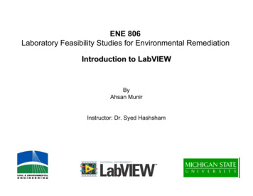
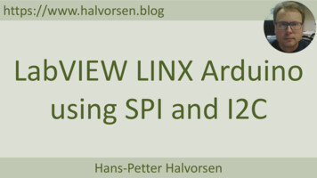
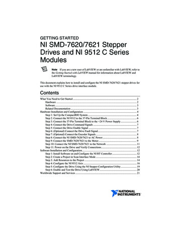
Image Display ControlUse the Image Display control to display an image on the LabVIEW frontpanel, as shown in the following figure. You can access the ImageDisplay control by right-clicking the front panel and selecting Vision.1 Display Area3 ROI Tools Template2 Image Information Indicator 4 ScrollbarsTo display an image, wire the image output of an NI Vision VI into theImage Display terminal on the block diagram, as shown in the followingfigure.The Image Display control contains the following elements:Display area—Displays an image.Image information indicator—Displays information about yourimage and the ROI that you are currently drawing.ROI tools palette—Contains tools for drawing ROIs, panning, andzooming. Unlike external display windows, each Image Displaycontrol uses its own set of tools.
Scrollbars—Allows you to position the image in the display area.During design time, you can customize the appearance of the control byrearranging the control elements, configuring properties through theshortcut menu, or selecting the control and clicking Edit»CustomizeControl.During run time, you can customize many parts of the control usingproperty nodes.Note Not all functionality available during design time is availableat run time.To create a property node, right-click the control and selectCreate»Property Node. Click the Property Node once to see theproperties you can configure. Properties specific to the Image Displaycontrol appear at the end of the list.The following list describes a subset of the properties available for theImage Display control:Snapshot Mode—Determines if the control makes a copy of theimage or has a reference to the image. When you enable theSnapshot Mode, if the inspection image changes later in yourapplication, the Image Display control continues to display theimage as it was when the image was wired into the Image Displaycontrol.Enabling the Snapshot Mode may reduce the speed of yourapplication because the control makes a copy of the image. Enablethis property when you want to display a snapshot of the image intime. Disable this property when you need to display resultsquickly, such as during a grab acquisition. The Snapshot Modeproperty is disabled by default.Note To cause the Image Display control to refresh the imageimmediately, use the Refresh Image method. To create a method,right-click the control, and select Create»Invoke Node. Click theInvoke Node once to see the available methods. Methods specificto the Image Display control appear at the end of the shortcutmenu.Palette—Determines which color palette the Image Display control
uses to display images. You can configure the control to use apredefined color palette or a custom color palette. Define a customcolor palette with the User Palette property node. You also canchange the color palette of the control or an image probe at runtime by right-clicking the Image Display control.Maximum Contour Count—Sets the maximum number of ROIcontours a user can draw on an image display.The Image Display control also includes the following methods:Get Last Event—Returns the last user event, resulting frommouse movements and clicks, on the Image Display control. Thismethod has the same behavior as the IMAQ WindLastEvent VI forexternal display windows.Clear ROI—Removes any ROIs on the Image Display control.Refresh Image—Refreshes the display to show the latest image.This method is useful if the snapshot control is disabled, but youwant the Image Display control to show the latest changes to theimage.
Add Calibration InformationIf you want to attach the calibration information of the current setup toeach image you acquire, use the IMAQ Set Calibration Info VI. This VItakes in a source image containing
NI Vision for LabVIEW Basics June 2008, 371007D-01 NI Vision for LabVIEW—a part of the NI Vision Development Module—is a library of LabVIEW VIs you can use to create machine vision and scientific imaging applications. This help file guides you through tasks beginning with setting up your imaging system to taking measurements.