Transcription
Low Voltage ProductsLow Voltage Capacitor BanksPower Factor Correction Solutions
ABB LV Capacitor BanksThe Most Comprehensive Solution forAutomatic Power Factor Correction2 ABB LV Capacitor Banks Low Voltage Capacitor Banks
Smart Solutions for Automatic Power Factor CorrectionPowerful and compactABB World renowned CLMD capacitors with a speciallydesigned ventilation system allow ABB capacitor banks to reacha maximum reactive power within a minimum volume.Easy to select– Capacitor banks available in 5 versions : Series 100, series300, series 500, series 700 and CLM3, as automatic,auxiliary and fixed units.– Capacitor bank with reactors available in 3 versions: Series300R, series 500R and CLMR, as automatic, auxiliary andfixed units.– CLM3 and CLMR high range of capacitor banks available in4 sizes depending on step quantity, as automatic, auxiliaryand fixed units.Reliable and safeThe reliability of ABB capacitor banks is based on a set of ABBcomponents exclusively designed for reactive power compensation applications.ABB capacitor banks come with a Type 1 protection level(closed door) and optional Type 12 and 3R version available onrequest.Easy to install– Complete unit, factory tested and ready for connectionCommissioning may be completely automatic– Ample space for wiring for control wires and power cables– The series 700, series 500R, CLM3 and CLMR cubicles areequipped with lifting eye-bolts for easy handling.– Auxiliary units are equipped with interconnection wires onterminals for fast connection to the master unit controller.Easy to useThe multiple automatic functions of the Power Factor Correction(RVT) and its user-friendly interface make the ABB capacitorbank very easy to operate.Key features & benefitsModular designAllows installation of additional power and switch modules aswell as various options. Additional units may be connected inparallel.OptionsCan be factory installed; anti-resonance reactors, filters, fans,blown fuse indication, non-fused, fused disconnect switchesand circuit breakers.Low lossesCapacitor total losses are less than 0.5 watts per kvar. Autobank total losses (without reactors), including accessories suchas Power Factor Controller and contactors are less than 1.5watts per kvar.Unique sequential protection systemEnsures that each individual capacitor element is selectively andreliably disconnected from the circuit at the end of its life.Life cycleLow losses and the self-healing properties of ABB capacitorelements help to ensure long operating life.SafetyABB capacitors are manufactured with vermiculite, a non-flammableand nontoxic material. The dry vermiculite safely absorbs anyenergy produced within the capacitor enclosure and preventsany fire hazard in case of failure. Unique cooling fans are fittedto surround each capacitor element providing effective heatdissipationComplianceCSA / ULLow Voltage Capacitor Banks Smart Solutions for Automatic Power Factor Correction 3
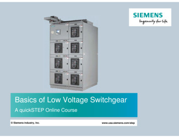
ABB Capacitor Banks Series 100, 300, 500, 700, 300R and 500RThe New ABB Efficient Ranges of Capacitor BanksSeriesMax. StagesMax. kvar/StepMax. kvarVoltageDimension (inches)TypeAprox. Weight10031545480 / 60024 x 20 x 101, 12, 3R90 lbTop300350150480 / 60036 x 30 x 161, 12, 3R200 lbTop / Side500550250480 / 60060 x 36 x 161, 12, 3R300 lbTop / Side7005100500480 / 60072 x 42 x 201, 12, 3R500 lbTop / Side300R350150480 / 60060 x 36 x 161, 12, 3R400 lbTop / Side500R550250480 / 60072 x 42 x 201, 12, 3R650 lbTop / SideThe ABB capacitor bank:– is a powerful and compact automatic bank.– is very easy to install and to operate.– provide a high level of reliability and security.4 ABB Capacitor Banks Series 100, 300, 500, 700, 300R and 500R Low Voltage Capacitor BanksCable entry
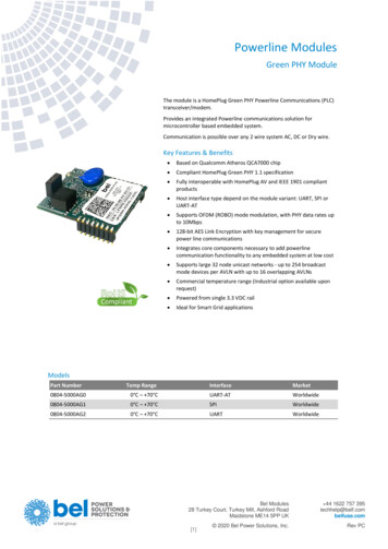
ABB CLM3 and CLMR Capacitor Banks SeriesMore Modularity and Ease of ConfigurationCLM3 – Automatic capacitor bankPossible configurations– 4-5-6-7-8 steps of single units.– Main protection can be added to the bank on request.– Maximum step size is 100 kvar @ 480V / 600V.Technical specification– Maximum kvar size 1200 kvar @ 480V / 600V– Dimensions: depends on the size 4 steps (90‘‘H x 38‘‘W x 20‘‘D) 5 steps (90‘‘H x 50‘‘W x 20‘‘D) 6 steps (90‘‘H x 62‘‘W x 20‘‘D) 7/8 steps (90‘‘H x 74‘‘W x 20‘‘D)– Weight: depend on bank configuration– Cable entry: top, bottom or side– Up 12 steps configuration with slave unitCLMR – Detuned capacitor bank(with reactors)Possible configurations– 3-4-5-6 steps.– Main protection can be added to the bank on request.– Maximum step size is 100 kvar @ 480V / 600V.Technical specification– Maximum kvar size 1200 kvar @ 480V / 600V– Dimensions: depends on the size 3 steps (90‘‘H x 38‘‘W x 20‘‘D) 4 steps (90‘‘H x 50‘‘W x 20‘‘D) 5 steps (90‘‘H x 62‘‘W x 20‘‘D) 6 steps (90‘‘H x 74‘‘W x 20‘‘D)– Weight: depend on bank configuration– Cable entry: top, bottom or side– Up 12 steps configuration with slave unitLow Voltage Capacitor Banks ABB CLM3 and CLMR Capacitor Banks Series 5
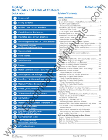
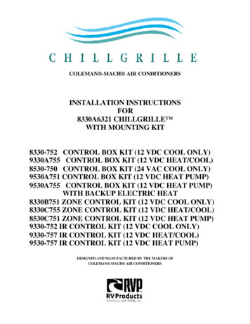
Technical DataABB capacitorsThe dielectric of the capacitor windings is made of in-housemetallized polypropylene film resulting in exceptional properties:– High voltage withstands capability.– Excellent peak current handling capacity.– High capacitance stability.– Long life even under high electrical stress.– Very low losses.– Exceptional self-healing properties.– Fire protection.CLMD33C capacitors, utilized in series 300 to 700 bankcomes with a unique voltage rating suitable for all voltagenetworks– The CLMD33C protection system offers reliable and safeprotection. It is based on: The instant reaction of state of the art overpressuredetection and disconnection devices. Double casing insulation protects the windings from theenvironment and assures high capacitance stability over thewhole capacitor service life.– The CLMD33C is suitable for a maximum ambient temperatureof 55 C (class D) and a minimum of -25 C.– The ISO 9001 and 14001 certification guarantees ourcommitment to the environment.Wire connectionMetal end sprayIn-house metallisedpolypropylene film (unique profile)Secondary foil windingBiaxially orientedpolypropylene dielectricThermo-setting encapsulationFuse linkPlastic caseConnection stud 5/16” x 1-3/4”Connection busbars 1/8” x 1”Aluminum terminal plateInsulation glass polyester sheetDischarge resistorsDry type self-healing capacitor windingsSteel enclosure bodyGround stud 5/16” x 1”6 Technical Data Low Voltage Capacitor Banks
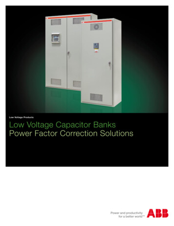
RVT – Power Factor ControllerFor Maximum Protection of Your Capacitor Bank Against TemporaryDeterioration of Your Network QualityLCD display with indication of:– Full graphics display– Inductive/Capacitive Power Factor– Active outputs– Demand for switching on/off of a capacitor step– Alarm conditions– Overtemperature condition– Phase shift– C/k– Number of outputs– Type of switching sequence– Alarm conditionsKeypadEasy commissioning with automatic recognition of:– Special connections (Single-phase, CT leads)– Number of outputs– Number of outputs– Type of switching sequenceAutomatic/manual modeModbus adapterAdditional features for the RVT power factor controller:– Programmable protection thresholds (under voltage, overtemperature, excessive harmonic distortion, etc ). The RVTprotects your capacitor bank. It is recommended forinstallation where over voltage, resonance or over temperatureoccurs.– Guided navigation and programming.– Network information and bank monitoring (voltage, current,harmonic spectrum, etc.).– Optional RS-485 Modbus adapter allowing communicationwith a monitoring system. All RVT parameters are remotelyaccessible (including harmonic spectra and tables).– Multi-language support.– Help button giving instant access to a description of all RVTfeatures and functionality.– Optional printer connection.– Input contacts for day/night power factor correction (cos ϕ)and external alarm.– Output contacts for alarm and fan relays (For furtherinformation on the RVT controller, please refer to the technicalspec of the RVT controller).– BacklitLow Voltage Capacitor Banks RVT – Power Factor Controller 7
ComponentsABB contactorsContactors have been specially selected for their excellenthandling capability during endurance tests.UA contactors equipped with damping resistorsThe UA contactors are fitted with a special front-mountedblock ensuring the serial insertion into the circuit of damping resistors limiting current peak on energizing of the capacitor bank.This connection also ensures capacitor pre-charging in order tolimit the second current peak occurring on closing of the mainpoles a few milliseconds later.Other options– Main circuit-breaker.– Main disconnect switch.– Main fusible disconnect switch.– Main fusible disconnect switch with blown fuse indicators.– Indicating lights; blown fuse indicators, state indicators, etc – Metering devices; ammeter, voltmeter, etc – Protection types; type 12, type 3R, dripshield, etc – Enclosure mounting brackets and legs.Wiring diagramPlain autobanksABB reactors (for series R execution)The dry type resin embedded reactors are specially designed tosuit the reactive power compensation application. Their exceptional linearity and thermal stress resistance characteristics ensurea high reliability degree even in case of temporary overvoltage.Tuned/detuned autobanksVentilationExcept for series 100 systems, all capacitor bank are equippedwith a ventilation system specially selected for their durationlongevity. The capacitor bank ventilation system consists of fanswith temperature-dependent probes which provide the fans withthe necessary thermal data. In case of temporary overheating,the capacitor bank is automatically deactivated.8 Components Low Voltage Capacitor Banks
Part Number ConfigurationB 03 G - 60 0100 B 2 1 - 1 0 0Bank type:B Automatic bankA Auxiliary bank (Optional)F Fixed bank (Optional)S Semi-Automatic bank (Optional)Enclosure model:01 Series 100 (24”H x 20”W x 12”D), up to 3 steps03 Series 300 (36”H x 30”W x 16”D), up to 3-5 steps05 Series 500 (60”H x 36”W x 16”D), up to 5 steps07 Series 700 (72”H x 42”W x 20”D), up to 5 stepsR3 Series 300R (60”H x 36”W x 16”D), up to 3 stepsR5 Series 500R (72”H x 42”W x 20”D), up to 5 stepsMA CLM3 (90”H x 38”W x 20”D), up to 4 stepsMB CLM3 (90”H x 50”W x 20”D), up to 5 stepsMC CLM3 (90”H x 62”W x 20”D), up to 6 stepsMD CLM3 (90”H x 74”W x 20”D), up to 8 stepsRA CLMR (90”H x 38”W x 20”D), up to 3 stepsRB CLMR (90”H x 50”W x 20”D), up to 4 stepsRC CLMR (90”H x 62”W x 20”D), up to 5 stepsRD CLMR (90”H x 74”W x 20”D), up to 6 stepsRE CLMR (42”H x 24”W x 20”D), 1 step onlyRF CLMR (54”H x 36”W x 20”D), up to 2 stepXX Multiple enclosures individual incoming (Optional)YY Multiple enclosures single incoming (Optional)Enclosure type:G Type 1D Type 12R Type 3R (Optional)Network voltage:20 208 Volts (Optional)22 220 Volts (Optional)24 240 Volts (Optional)48 480 Volts60 600 VoltsKvar rating:0010 10 kvar0100 100 kvar0200 200 kvar0300 300 kvar0400 400 kvar0500 500 kvar0700 700 kvar0800 800 kvar0900 900 kvar (Optional)1000 1000 kvar (Optional)1200 1200 kvar (Optional)Main incoming:B Busbars or splitterN Non-fusible disc. switchF Fusible disconnect switch (Fuse not included)C Circuit breakerOption: (CSA / UL)0 / A No options1 / B BFIs (Optional)2 / C State indicators (Optional)3 / D BFI’s & State indicators (Optional)4 / E Reactor “Overheat” indicators (Optional)5 / F Pilot light “Power On” (Optional)6 / G Options 1, 4 & 5 (Optional)7 / H Push to test “BFI” (Optional)8 / I Over Voltage relay “OVR” (Optional)9 / J To be determined (Optional)Frequency:0 No Reactor at 60Hz1 170 Hz (Optional)2 227 Hz3 245 Hz (Optional)4 252 Hz (Optional)5 282 Hz (Optional)6 190 Hz at 50Hz (Optional)A No Reactor at 50Hz (Optional)Switching sequences:0 No switching, for Fixed Banks1 1:1:1:1:1:.:12 1:2:2:2:2:.:23 1:2:4:4:4:.:4 (Optional)4 1:2:4:8:8:.:8 (Optional)5 1:1:2:2:2:.:2 (Optional)6 1:1:2:4:4:.:4 (Optional)7 1:1:2:4:8:.:8 (Optional)8 1:2:3:3:3:.:3 (Optional)9 1:2:3:6:6:.:6 (Optional)A 1:1:2:3:3:.:3 (Optional)B 1:1:2:3:6:.:6 (Optional)Future steps:0 0 Step1 1 Step2 2 Steps3 3 Steps4 4 Steps5 5 Steps6 6 Steps7 7 Steps8 8 Steps9 9 StepsA 10 StepsNumber of steps:2 2 Steps3 3 Steps4 4 Steps5 5 Steps6 6 Steps7 7 Steps8 8 Steps9 9 StepsA 10 StepsB 11 StepsC 12 StepsLow Voltage Capacitor Banks Part Number Configuration 9
Component SelectionStandard selection for contactors and branch fuses480V600VContactor, fuse and cable size selectionsContactor, fuse and cable size selectionsKvarCable sizeKvarCable sizeper stepContactorsFuse ratings(AWG)per stepContactorsFuse 11/090UA95-30-00-RA-84A60C150-1212100A145-30-11-84 (*)A60C200-1211/0 (*)100UA110-30-00-RA-84A60C175-1211* ABB Inc. suggests when installing the 3 cables between the capacitor-contactor and the capacitor itself to follow these recommendations. The cables should be rolled at least 4 timeswith an inside diameter of 4 inches. Phase “A’’ should be wound in one direction, phase “B’’ in the opposite direction and phase “C’’ in the same direction as phase A. The basic reasonof having this “Air Coil reactance’’ is to lower the inrush current when the capacitor is energized.Standard selection for main incoming splitter x. kvarbank typelugsMax. kvarbank typelugs45Series 1001 x (#6AWG - #350MCM)45Series 1001 x (#6AWG - #350MCM)150Series 3002 x (#4AWG - #500MCM)150Series 3002 x (#4AWG - #500MCM)250Series 5002 x (4AWG - #500MCM)250Series 5002 x (4AWG - #500MCM)500Series 7002 x (#4AWG - #500MCM)500Series 7002 x (#4AWG - #500MCM)600CLM3 / CLMR4 x (#4AWG - #500MCM)600CLM3 / CLMR4 x (#4AWG - #500MCM)600 CLM3 / CLMR4 x (#4AWG - #500MCM)600 CLM3 / CLMR4 x (#4AWG - #500MCM)10 Component Selection Low Voltage Capacitor Banks
Standard selection for main disconnect lDisconnectCurrentmax. kvarswitchesrating (Amp.)lugsmax. kvarswitchesrating (Amp.)Incominglugs50OT100E31001 x (#8AWG - #1/0AWG)60OT100E31001 x (#8AWG - #1/0AWG)110OT200U122001 x (#4AWG - #300MCM)135OT200U122001 x (#4AWG - #300MCM)220OT400U124001 x (#2AWG - #600MCM)275OT400U124001 x (#2AWG - #600MCM)330OT600U126002 x (#2AWG - #600MCM)415OT600U126002 x (#2AWG - #600MCM)440OT800U128004 x (#2AWG - #600MCM)550OT800U128004 x (#2AWG - #600MCM)660OT1200U1212004 x (#2AWG - #600MCM)830OT1200U1212004 x (#2AWG - #600MCM)880OT1600U1216006 x (#1/0AWG - #750MCM)N/AOT1600U1216006 x (#1/0AWG - #750MCM)1100OT2000U1220006 x (#1/0AWG - #750MCM)N/AOT2000U1220006 x (#1/0AWG - #750MCM)Standard selection for main fusible disconnect switches480V600VTotalFusible Disconnectmax. sible Disconnectlugsmax. kvarswitches100 1 x (#14AWG - #2/0AWG)100OS200J12100 1 x (#14AWG - #2/0AWG)OS200J12200 1 x (#4AWG - #300MCM)125OS200J12200 1 x (#4AWG - #300MCM)OS400J124001 x (#2AWG - #600MCM250OS400J12400300OS600J12600 2 x (#2AWG - #600MCM)375OS600J12600 2 x (#2AWG - #600MCM)400OS800L12800 2 x (#2AWG - #600MCM)500OS800L12800 2 x (#2AWG - #600MCM)600OS1200L121200 4 x (#2AWG - #600MCM)750OS1200L121200 4 x (#2AWG - #600MCM)rating (Amp.)Currentrating (Amp.)Incominglugs1 x (#2AWG - #600MCMStandard selection for main circuit breakers480VTotal600VCircuit breakermax. kvarCurrentIncomingrating (Amp.)lugsTotalCircuit breakermax. kvarCurrentIncomingrating (Amp.)lugs1 x (#14AWG - #1/0AWG)55TS3N100TW1001 x (#14AWG - #1/0AWG)60TS3N100TW100110T4N250BW2001 x (#6WG - #350MCM)135T4N250BW2001 x (#6WG - #350MCM)220T5N400BW4002 x (#3/0AWG - #250MCM)275T5N400BW4002 x (#3/0AWG - #250MCM)330T6N600BW6002 x (#250MCM - #500MCM)415T6N600BW6002 x (#250MCM - #500MCM)440T6N800BW8003 x (#2/0AWG - #400MCM)550T6N800BW8003 x (#2/0AWG - #400MCM)660T7H1000BW10004 x (#4/0AWG - #500MCM)690T7H1000BW10004 x (#4/0AWG - #500MCM)880T7H1200BW12004 x (#4/0AWG - #500MCM)830T7H1200BW12004 x (#4/0AWG - #500MCM)Low Voltage Capacitor Banks Component Selection 11
Standard Assemblies(Series 100, 300, 500, 700, 300R and 500R)480V600VSeries 100Series 100Total kvarPart numberSteps x kvarMain protection (A)Total kvarPart numberSteps x kvarMain protection x510020B01G-480020B30-5001 x 10 2 x 510020B01G-600020B30-1501 x 10 2 x 510025B01G-480025B30-2002 x 10 1 x 510025B01G-600025B30-1202 x 10 1 x 510030B01G-480030B30-1003 x 1010030B01G-600030B30-1003 x 1010045B01G-480045B30-1003 x 1510045B01G-600045B30-1003 x 15100480V600VSeries 300Series 300Total kvarPart numberSteps x kvarMain protection (A)Total kvarPart numberSteps x kvarMain protection (A)60B03G-480060B30-1003 x 2015060B03G-600060B30-1003 x 2010075B03G-480075B30-1003 x 2515075B03G-600075B30-1003 x 2515090B03G-480090B30-1003 x 3020090B03G-600090B30-1003 x 30150100B03G-480100B30-5001 x 50 2 x 25200100B03G-600100B30-5001 x 50 2 x 25150120B03G-480120B30-1003 x 40225120B03G-600120B30-1003 x 40200135B03G-480135B30-1003 x 45250135B03G-600135B30-1003 x 45200150B03G-480150B30-1003 x 50400150B03G-600150B30-1003 x 50225480V600VSeries 500Series 500Total kvarPart numberSteps x kvarMain protection (A)Total kvarPart numberSteps x kvarMain protection (A)175B05G-480175B30-3001x100 1x50 1x25400175B05G-600175B30-3001x100 1x50 1x25250200B05G-480200B40-1004 x 50400200B05G-600200B40-1004 x 50400200B05G-480200B30-5001 x 100 2 x 50400200B05G-600200B30-5001 x 100 2 x 50400225B05G-480225B50-2004 x 50 1 x 25600225B05G-600225B50-2004 x 50 1 x 25400250B05G-480250B30-2002 x 100 1 x 50600250B05G-600250B30-2002 x 100 1 x 50400250B05G-480250B50-1005 x 50600250B05G-600250B50-1005 x 50400300BR5G-600300B60-1006 x 50600480V600VSeries 700Series 700Total kvarPart numberSteps x kvarMain protection (A)Total kvarPart numberSteps x kvarMain protection (A)275B07G-480275B60-3005 x 50 1 x 25600275B07G-600275B60-3005 x 50 1 x 25400300B07G-480300B60-1006 x 50600300B07G-600300B60-1006 x 50600350B07G-480350B40-5003 x 100 1 x 50800350B07G-600350B40-5003 x 100 1 x 50600400B07G-480400B40-2004 x 100800400B07G-600400B40-2004 x 100600450B07G-480450B50-2004 x 100 1 x 50800450B07G-600450B50-2004 x 100 1 x 50800500B07G-480500B50-1005 x 1001000500B07G-600500B50-1005 x 10080012 Standard Assemblies Low Voltage Capacitor Banks
480V600VSeries 300RSeries 300RTotal kvarPart numberSteps x kvarMain protection (A)Total kvarPart numberSteps x kvarMain protection (A)60BR3G-480060B30-1203 x 2015060BR3G-600060B30-1203 x 2010075BR3G-480075B30-1203 x 2515075BR3G-600075B30-1203 x 25150100BR3G-480100B30-5201 x 50 2 x 25200100BR3G-600100B30-5201 x 50 2 x 25150125BR3G-480125B30-2202 x 50 1 x 25250125BR3G-600125B30-2202 x 50 1 x 25200150BR3G-480150B30-1203 x 50400150BR3G-600150B30-1203 x 50225480V600VSeries 500RSeries 500RTotal kvarPart numberSteps x kvarMain protection (A)Total kvarPart numberSteps x kvarMain protection (A)175BR5G-480175B30-3201x100 1x50 1x25400175BR5G-600175B30-3201x100 1x50 1x25250200BR5G-480200B40-1204 x 50400200BR5G-600200B40-1204 x 50400225BR5G-480225B50-2204 x 50 1 x 25600225BR5G-600225B50-2204 x 50 1 x 25400250BR5G-480250B50-1205 x 50600250BR5G-600250B50-1205 x 50600300BR5G-480300B60-1206 x 50600300BR5G-600300B60-1206 x 50600For 208 / 240 Vac applications, please contact ABB sales office (see back cover of this brochure).Main Lugs are provided with each assemblies and main protection may be added as an option.Disconnect switches, fusible disconnect switches or molded case circuit breakers may be added as a main protection.Type 12 and 3R are available options upon request, please contact ABB sales office.Additional sizes, ratings, or options are available upon request.Low Voltage Capacitor Banks Standard Assemblies 13
Technical SpecificationsNominal voltage and frequency:208 up to 600V – 60Hz (standard range)Connection:Three phase.Configuration:Series 100, 300, 500, 700, 300R, 500R, CLM3 and CLMR: master unit only.Series 100, 300, 500, 700, 300R, 500R, CLM3 and CLMR: auxiliary unit only.Auxiliary units are not equipped with PF controller but are fitted with interconnection wires to the master unit.Automatic capacitor bank tests:– Insulation test.– Functional test.Protection:– Type 1– Type 12 (optional)– Type 3R (optional)Color:Gray ASA61Power factor setting:From 0.7 inductive to 0.7 capacitive.Ambient temperature:-10 C/ 40 CStarting current setting (C/k):From 0.01 A to 5 A for the RVTVentilation:Forced for the series 300, 500, 700, 300R, 500R, CLM3 and CLMROperation:Automatic or manual setting of the controller with indication of:– The number of active outputs.– The inductive or capacitive power factor.– Alarm conditions.– Overtemperature.– Demand for switching on/off of a capacitor step.– Overvoltage and undervoltage protection.Dimensions:– Series 10024”H x 20”W x 12”D (609mm x 508mm x 304mm)– Series 30036”H x 30”W x 16”D (915mm x 762mm x 406mm)– Series 500 and 300R60”H x 36”W x 16”D (1524mm x 915mm x 406mm)– Series 700 and 500R72”H x 42”W x 20”D (1828mm x 1066mm x 508mm)– Series CLM34 Steps, 90‘‘H x 38‘‘W x 20‘‘D (2286mm x 965mm x 508mm)5 Steps, 90‘‘H x 50‘‘W x 20‘‘D (2286mm x 1270mm x 508mm)6 Steps, 90‘‘H x 62‘‘W x 20‘‘D (2286mm x 1575mm x 508mm)8 Steps, 90‘‘H x 74‘‘W x 20‘‘D (2286mm x 1880mm x 508mm)– Series CLMR3 Steps, 90‘‘H x 38‘‘W x 20‘‘D (2286mm x 965mm x 508mm)4 Steps, 90‘‘H x 50‘‘W x 20‘‘D (2286mm x 1270mm x 508mm)5 Steps, 90‘‘H x 62‘‘W x 20‘‘D (2286mm x 1575mm x 508mm)6 Steps, 90‘‘H x 74‘‘W x 20‘‘D (2286mm x 1880mm x 508mm)Losses:Dielectric losses: less than 0.2 Watt/kvar.Capacitor total losses: less than 0.5 Watt/kvar (dischargeresistors included).Automatic bank total losses:– without reactors: less than 1.5 Watt/kvar (including lossesfrom all accessories),– with reactors: less than 5.5 Watt/kvar (including accessorieslosses).Capacitors:Dry type, self-healing, according to EN 60831-1&2.Voltage test: 2.15 times Un (Un Line to line) between terminals for a duration of10 s. at the rated frequency (above EN 60831-1&2).Acceptable overloads:– Overvoltage tolerance: 10% max. Intermittently.– Overcurrent tolerance: 30% permanently.Temperature range: -25 C / class D according to IEC 60831-1&2.The automatic capacitor bank complies with:– CSA C22.2.C190.– UL/cUL 508A.Approximate weights:– Series 100, 90lbs (45kg)– Series 300, 200lbs (90kg), series 300R, 380lbs (172kg)– Series 500, 300lbs (137kg), series 500R, 600lbs (272kg)– Series 700, 500lbs (227kg)– Series CLM3, depend on bank configuration.– Series CLMR, depend on bank configuration.Installation:Enclosure:Series 100, 300, 500 and 300R;– Wall mounting (fixation brackets optional).– Top or side cable entry.Series 700, 500R, CLM3 and CLMR;– Modular free-standing cubicle.– Floor fixation.– Lifting eye-bolts provided.– Top or side cable entry.14 Technical Specifications Low Voltage Capacitor Banks
NotesLow Voltage Capacitor Banks Notes 15
Regional offices across CanadaRegional offices across USAEastern regionABB Inc.2117 – 32e AvenueLachine, QC H8T 3J1Tel.: 514-420-3100Fax: 514-420-3137Toll Free: 1 800-567-0283ABB Inc.3700 West Sam HoustonParkway SouthHouston, TX 77042Toll Free: 1 888-385-1221Central regionABB Inc.201 Westcreek Blvd.Brampton, ON L6T 5S6Tel.: 905-460-3000Fax: 905-460-3395Western regionABB Inc.#110, 4411-6th Avenue S.E.Calgary, AB T2G 4E8Tel.: 403-278-7111Fax: 403-278-8232ABB Inc.9418-39th Avenue NWEdmonton, AB T6E 5T9Tel.: 780 447-4677Fax: 780 455-4527www.abb.caABB Inc.400 Crown Colony DriveQuincy, MA 02169Toll Free: 1 888-385-1221www.abb.comWhile all care has been taken to ensure that the informationcontained in this publication is correct, no responsibilitycan be accepted for any inaccuracy. The Company reservesthe right to alter or modify the information contained hereinat any time in the light of technical or other developments.Technical specifications are valid under normal operatingconditions only. The Company does not accept anyresponsibility for any misuse of the product and cannot beheld liable for indirect or consequential damages. Copyright 2011 ABB Inc. All rights reserved.1SXP981002D0202/April 2011Contact Us
a maximum reactive power within a minimum volume. Easy to select - Capacitor banks available in 5 versions : Series 100, series 300, series 500, series 700 and CLM3, as automatic, auxiliary and fixed units. - Capacitor bank with reactors available in 3 versions: Series 300R, series 500R and CLMR, as automatic, auxiliary and fixed units.