Transcription
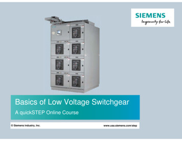
Basics of Low Voltage SwitchgearA quickSTEP Online Course Siemens industry, Inc.www.usa.siemens.com/step
TrademarksSiemens is a trademark of Siemens AG. Product names mentioned may be trademarks or registeredtrademarks of their respective companies.ANSI is a registered trademark of American National Standards InstituteNational Electrical Code and NEC and NFPA 70 are registered trademarks of the National FireProtection Association.NEMA is a registered trademark and service mark of the National Electrical Manufacturers Association.UL is a registered trademark of UL, LLC.Other trademarks are the property of their respective owners. Siemens Industry, Inc. 2017Page 1-2
Course TopicsWelcome to Basics of Low Voltage Switchgear.This course covers the following topics:Chapter 1 - Introduction Overview WL LV Power Circuit BreakersChapter 2 – WL LV Switchgear WL LV Switchgear Design Arc Resistant LV Switchgear Sm@rtGear LV SwitchgearFinal ExamIf you do not have an understanding of basicelectrical concepts, you should complete Basicsof Electricity before attempting this course. Siemens Industry, Inc. 2017Page 1-3
Course ObjectivesUpon completion of this course you will be able to State the differences in operating voltage between low voltage and medium voltage switchgear List the maximum voltage rating and maximum bus current ratings for WL low voltage switchgear Describe the most important design characteristics of WL low voltage power circuit breakers List the most significant specifications that affect the design of low voltage switchgear Identify the range of continuous current ratings, interrupting ratings, and short-time withstand ratingsavailable for WL low voltage power circuit breakers Identify operational features of WL low voltage power circuit breakers Describe the key differences among the various electronic trip units available for WL circuit breakers List the communication options available for WL circuit breakers List the enclosure types available for standard WL low voltage switchgear List the types of sections and section widths commonly for WL low voltage switchgear. Identify the ANSI/IEEE arc resistant testing standard that applies to both low voltage and mediumvoltage switchgear Describe the difference between accessibility levels 1 and 2 for arc resistant switchgear Describe the key similarities and differences between WL low voltage switchgear and the arcresistant version List important features of Sm@rtgearTM LV switchgear. Siemens Industry, Inc. 2017Page 1-4
SITRAIN Training for IndustryOnline Self-paced Learning – Programs with maximum flexibility so students can easily fitcourses into their busy schedulesVirtual Instructor-led Learning - Classroom lectures delivered in the convenience of yourhome or officeClassroom Learning - Expert and professional instructors, proven courseware, and qualityworkstations combine for the most effective classroom experience possible at your facility oroursHow-to Video Library - Quick, affordable, task-based learning options for a broad range ofautomation topics for training or purchaseSimulators - World-class simulation systems available for training or purchaseThis course also describes learning options available from the Siemens SITRAIN USA organization and ourglobal SITRAIN partners. For additional information: www.usa.siemens.com/sitrain Siemens Industry, Inc. 2017Page 1-5
Power DistributionPower from a power generating plant is distributed tocustomers through transmission lines and substations. Themost efficient way to do this is to increase the voltage while atthe same time reducing the current. Electric utilities, whichmust provide power to customers of various types, usetransmission systems that operate in the high voltage or extrahigh voltage range.Once the electrical energy gets near the end user, the utilitysteps down the voltage to the level needed by the user. Theamount by which the voltage is stepped down at the user enddepends on the needs of the facility. Many large commercialor industrial facilities have service entrance equipment thatoperates in the medium voltage range. Other facilities havelow voltage equipment at the service entrance. Siemens Industry, Inc. 2017Medium voltage (MV) systems generally operate between1000 and 38,000 volts (1 to 38 kV), although some MVsystems can operate above 38 kV. The switchgear covered inthis course is referred to as low voltage (LV) equipment. Forthe purposes of this discussion of power distributionequipment, LV systems operate at 1000 VAC (nominal) orbelow. Keep in mind that to account for power systemdifferences the maximum voltage of equipment is usuallyhigher than the nominal system voltage.Page 1-6
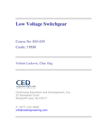
Medium Voltage SwitchgearA large industrial facility receives electrical powerfrom the utility company at high transmission voltagelevels. The voltage is stepped down to a mediumvoltage or low voltage level at the substation fordistribution throughout the facility. Large industrialfacilities can be spread out over several acres andmay incorporate many large buildings. Multiple MVswitchgear units, sometimes called MV metal-cladswitchgear, could be used if the power demand islarge enough.Switchgear is a compartmentalized system ofcoordinated devices used for power distribution,control, and circuit protection. Switchgear performsthe same function as switchboards, but differentstandards dictate the design of switchgear. Inaddition, because medium voltage (MV) switchgearmust handle higher levels of electrical energy andmust be capable of interrupting higher fault currents,it is larger and more heavily constructed.Siemens manufactures multiple types of MVswitchgear to meet varied customer requirementswith voltage ratings up to 42 kV. Siemens Industry, Inc. 2017Page 1-7
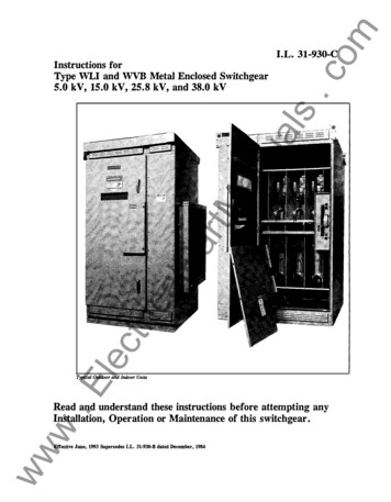
WL Low Voltage Metal-Enclosed SwitchgearA Siemens WL low voltage (LV) metal-enclosed switchgearassembly consists of one or more metal-enclosed verticalsections. WL LV switchgear is designed around the innovativefeatures of Siemens WL LV power circuit breakers. Each verticalsection consists of up to four individually-enclosed breaker orauxiliary compartments sized to provide uniform section height.Included in each assembly are components such as circuitbreakers, instrumentation and control equipment, transformers,relays, three-phase bus work, and all internal wiring, connectors,and other supporting equipment.WL switchgear has horizontal and vertical bus rated for 6000amps maximum. It is rated for use on 50 or 60 Hz, three-phase,three-wire or three-phase, four-wire systems with a maximumvoltage of 635 VAC.This course covers Siemens WL LV metal-enclosed switchgearand the WL low voltage power circuit breakers that thisequipment incorporates. An overview of the following variationsof WL LV switchgear is also included: four-pole WL LVswitchgear, front-connected WL LV switchgear, marine WL LVswitchgear, arc resistant LV switchgear, and Sm@rtGear WL LVswitchgear. Siemens Industry, Inc. 2017Page 1-8
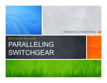
Large Facility Power Distribution ExampleIn large commercial, industrial, or institutional facilities, thesupplied voltage must be reduced multiple times toaccommodate the needs of various types of electricalequipment. While some machines require voltages above480 volts, most factories and many large commercial andinstitutional faculties use AC motors, drives, motor controlcenters, and other devices that operate on three-phase,480 volts and other equipment that requires even lower singlephase or three-phase voltages.In the accompanying example, power is stepped down at theutility company’s substation to 38,000 volts (38 kV) and appliedto the incoming section of the facility’s 38 kV medium voltagemetal-clad switchgear.One distribution branch is stepped down to 4.16 kV and anotherto 13.8 kV and further distributed through MV metal cladswitchgear units. A 13.8 kV branch is applied to a secondaryunit substation and further reduced to 480 volts. Further downthis path, a single-phase transformer reduces the voltage to120 V. Siemens Industry, Inc. 2017In this example, the LV switchgear is incorporated into asecondary unit substation. Keep in mind that LV switchgearsections may not set up in this configuration.Page 1-9
Secondary Unit SubstationsSome customers require an integrated assembly,called a secondary unit substation, to provideelectrical service to a facility. A secondary unitsubstation consists of a primary switch and one ormore transformers mechanically and electricallyconnected to switchboard or switchgear sections.All elements of the substation are engineered tothe specific needs of the application.The incoming service to the primary switch istypically 2.4 to 13.8 kV. The primary switch isused to connect and disconnect the secondaryunit substation from the incoming service. Thetransformer section can be liquid filled, ventilateddry type, or cast coil type and is used to stepdown the voltage to 600 V or below. The outgoingsections can be switchboard or LV switchgearsections. Siemens Industry, Inc. 2017Page 1-10
WL Low Voltage Power Circuit BreakersSiemens WL circuit breakers are designed to address theincreasingly demanding requirements of today’s electrical powerdistribution systems and incorporates the following characteristics. High reliability Compact size Ease of use Modularity of design Flexibility of system communications Safety-oriented featuresSiemens WL family of circuit breakers includes both insulatedcase circuit breakers that conform to the UL 489 specification andlow voltage power circuit breakers that conform to the UL 1066and corresponding ANSI and NEMA specifications. The WL circuitbreakers used in WL LV switchgear are LV power circuit breakers.One important characteristic of an LV power circuit breaker is itsability to withstand a designated level of fault current withoutdamage for a short time. This is important because an LV powercircuit breaker is often required to delay tripping for a short timewhen a fault current is sensed so that a downstream breakercloser to the fault has time to trip, thereby avoiding a largersystem outage. Siemens Industry, Inc. 2017Page 1-11
Low Voltage Switchgear StandardsThe terms switchboard and switchgear areoften confused because these terms aresimilar in spelling and both types ofequipment are used in power distributionsystems. However, low voltage switchgearconforms to ANSI, IEEE, and ULstandards that differ from NEMA and ULswitchboard standards.The accompanying chart shows the mostsignificant ANSI, IEEE, and UL standardsthat apply to LV switchgear assembliesand devices. Siemens Industry, Inc. 2017Page 1-12
Low Voltage Switchgear ApplicationsWL LV switchgear is designed for use in a wide variety of applications. The accompanying chart shows examples of typicalapplications for LV switchgear. Siemens Industry, Inc. 2017Page 1-13
Low Voltage Switchgear Versus SwitchboardsLV switchgear and switchboards are similar in appearanceand perform similar functions, but there are someimportant differences. In general, low voltage switchgear istypically more rugged than comparable switchboards. Thisdifference translates into a higher manufacturing cost andselling price for low voltage switchgear.Another important difference relates to the different designstandards for switchboards and LV switchgear. The U. S.standards for LV switchgear were provide earlier in thiscourse. In comparison, consider that switchboards aredesigned to NEMA PB-2 and UL 891 standards. Inaddition, shown in the accompany chart, switchboards arecapable of incorporating a broader range of overcurrentprotection devices. This means that more devicestandards apply to switchboards.In summary, There are applications that can be handledeffectively with either switchboards or LV switchgear;however, there continues to be a need for both types ofproducts. Switchboards offer flexibility and a lower initialcost, and LV switchgear offers increased ruggedness andreliability that for many companies translates into a lowertotal cost of ownership. Siemens Industry, Inc. 2017Page 1-14
Online Self-paced LearningWith Siemens online self-paced learning, you select thetopics and set your own pace for completing chosencourses. All course material can be accessed online.Instruction starts upon completing the purchase of asubscription.You can choose from over 500 courses consisting of highquality graphics, on-screen text, supporting voiceovernarration, and interactive exercises. Features includeprintable course content for reference and underlined keyvocabulary terms with definitions displayed with a simplemouse-over action.Depending on the subscription purchased, you can chooseany 10 or 25 courses or select the entire online self-pacedcourse catalog.These courses are offered 24/7/365, so you can begin yoursubscription at any time. From the date of registration,you have one year to complete your course selections.For additional information: www.usa.siemens.com/sitrain Siemens Industry, Inc. 2017Page 1-15
Chapter 1 – IntroductionThis chapter covers the followingtopics: Overview WL LV Power Circuit Breakers Siemens Industry, Inc. 2017Page 1-16
WL LV Three-Pole Power Circuit Breaker RatingsWL low voltage power circuit breakers, also referred to as WL UL 1066 circuit breakers, are used in WL low voltageswitchgear as drawout-mounted breakers. They have a rated maximum operating voltage of 635 VAC and are available intwo frame sizes with frame ratings from 800 to 6000 A and continuous current ratings from 200 to 6000 A. Additionaldetails for three-pole WL power circuit breakers are provided in the chart shown below. Note that frame size I is not shownhere because it only applies to WL circuit breakers that conform to the UL 489 specification. Ratings for four-pole WLpower circuit breakers are provided in the chart on the following page. Siemens Industry, Inc. 2017Page 1-17
WL LV Four-Pole Power Circuit Breaker RatingsFour-pole breakers provide the neutral isolation capability that is advantageous for low voltage switchgear applicationswhere multiple, separately-derived power sources are individually grounded. Ratings for four-pole WL power circuitbreakers are provided in the chart shown below. Note that frame size I is not shown here because it only applies to WLcircuit breakers that conform to the UL 489 specification. Siemens Industry, Inc. 2017Page 1-18
WL Circuit Breaker Operational FeaturesWL circuit breakers can be fused or unfusedand optionally delivered with any of theseoperating mechanisms: Manual operating mechanism withmechanical closing (standard) Manual operating mechanism withmechanical and electrically-interlockedclosing Motorized operating mechanism withmechanical and electrically-interlockedclosing.As shown in the accompanying graphic, WLcircuit breakers have a number of standard andoptional features that enhance the safety andusability of the breaker, reduce errors, andminimize training time. Siemens Industry, Inc. 2017Page 1-19
Ready-to-close IndicatorOne of the standard safety features of WLlow voltage power circuit breakers is theready-to-close indicator that provides an at-aglance visual indication that the all eight ofthe necessary conditions have been met andthe breaker is in the ready-to-close state.The WL circuit breaker is ready to close if thefollowing conditions are met;1. The breaker is in the open position2. The stored-energy springs are charged3. The under-voltage release (UVR) isenergized4. The shunt trip is not energized5. The closing coil is not energized6. No interlocks are activated7. The mechanical closing lockout is reset8. The racking handle is stowed away Siemens Industry, Inc. 2017Page 1-20
Modularity of DesignWL circuit breakershave a flexiblemodular design thatincludes commonplug-in accessories,field upgradeable tripunits, and fieldchangeable contactsand arc chutes.This design minimizesinventory, allows forlast-minute changes,and is cost-effectiveto support. Siemens Industry, Inc. 2017Page 1-21
Field Installable AccessoriesWL circuit breakers offer a variety accessories and trip units that are easily mounted at the front of the breaker and eachof these devices fits all frames. Examples of some of the more common accessories are shown in the accompanyinggraphic. Siemens Industry, Inc. 2017Page 1-22
Electronic Trip Units – Part 1Three electronic trip units (ETUs) are available for use withWL circuit breakers. The protective functions andadditional capabilities available for these trip units areshown in the accompanying diagram. Some of the optionalfunctions are briefly described below and on the next pageThe switch-selectable I2t or I4t characteristic curvefunction allows the breaker’s long-time characteristics tobe set to either an I2t curve or an I4t curve to make iteasier to achieve optimal coordination.Switchable parameter sets simplify adapting the system torapid changes, such as when power is switched betweenutility power and a generator. Switching betweenparameter sets can be done quickly and, if desired,remotely. Siemens Industry, Inc. 2017Page 1-23
Electronic Trip Units – Part 2Dynamic Arc-Flash Sentry (DAS) employs the unique dualprotection settings of the ETU776 trip unit coupled with theability to toggle to a lower arc flash parameter set. Anormal parameter set can be optimized for selective tripcoordination with the alternate parameter set optimized forlower arc flash energy levels initiated when someoneapproaches the arc flash protection boundary.Extended Instantaneous Protection (EIP) is designed toprovide any WL low voltage power circuit breaker with thecapability to be applied at the short-time withstand ratingof the breaker with no instantaneous override. This featuregives downstream breakers the maximum possible time toclear a fault and reduces the likelihood of a system-wideoutage. Siemens Industry, Inc. 2017Page 1-24
Electronic Trip Unit Modularity – Part 1The modularity of WL circuit breakers extendsto the ETUs. For example, any ETU model canbe installed in any WL circuit breaker. Inaddition, as described below, selected ETUmodels can be easily adapted to changingconditions in the field by the addition orreplacement of the following ETU modules: DisplayGround fault protectionRating plugMetering function/Metering function plusCommunication.The alphanumeric LCD display is an option forETU745 (shown in the accompanying graphic)and ETU748. ETU776 comes equipped with agraphical LCD display. Siemens Industry, Inc. 2017Page 1-25
Electronic Trip Unit Modularity – Part 2Ground fault trip and alarm and ground-faultonly modules are available for ETU745,ETU748, and ETU776.The rating plug is a replaceable module used toset the continuous current rating for the circuitbreaker. Rating plugs are available for framesize II from 200 to 3200 amps and for framesize III from 800 to 6000 amps.The integrated metering function can beinstalled on ETU745, ETU748, and ETU776 tomeasure currents, voltages, power, energy,power factor, and frequency. All meteredquantities are real-time values with min/maxrecording. The metering module also providesadditional alarm setpoint and protective relayfunctions. The metering function plus modulehas additional recording capacity and supportsharmonic analysis. Siemens Industry, Inc. 2017Page 1-26
Communications Options – Part 1CubicleBUS forms the backbone of the WLcircuit breaker communication system.CubicleBUS is an internal system bus thatconnects all intelligent components in theWL circuit breaker and simplifies theconnection to external components.CubicleBUS is incorporated into all WLcircuit breakers with ETU745, ETU748, andETU776 trip units. The modular design ofthis system simplifies retrofitting ofcommunications functions. All modulesshown attached to CubicleBUS in theaccompanying graphic directly accessuseful circuit breaker data. Siemens Industry, Inc. 2017Page 1-27
Communications Options – Part 2With the addition of a COM15 PROFIBUSmodule for PROFIBUS DP communicationsor COM16 MODBUS module ( not shown)for MODBUS RTU communications, WLcircuit breakers with ETU745, ETU748, andETU776 trip units can have ETUparameters changed, and the breaker canbe opened and closed remotely. In addition,data can be shared with other systems. Fortrip units with the metering function ormetering function plus option, the breakercan take on an even wider role in a powermanagement system.The Breaker Data Adapter (BDA)incorporates configuration software andembedded web pages. This enables onlineconfiguration and diagnostics and allowsconfiguration data developed offline to bedownloaded to the trip unit.The BDA Plus has all the functionality ofthe BDA and can also connect to anEthernet network. Siemens Industry, Inc. 2017Page 1-28
CubicleBUS I/O ModulesA variety of CubicleBUS input/output (I/O) modules are available to expand thecapabilities of the WL circuit breaker. The following paragraphs summarize thecapabilities of this modules.The digital output module with rotary switch (not shown) allows up to six binarysignals to be connected to external signaling devices or used to control otherequipment. Digital and relay output versions of this module are available.The configurable digital output module allows up to six binary signals to betriggered by protective or setpoint events. Optionally, three of these outputs can beassigned in a logical-OR arrangement connected to up to six events. Both digitaland relay output versions of this module are available.The analog output module can be used to output a variety of measured values(amps, volts, power, power factor, etc.) to analog display devices on the cubicledoor. Up to two modules of this type can be connected to the WL breaker.The digital input module can connect to a maximum of six digital (24 VDC) inputs.This enables the status of a switch or the cubicle door to be communicated to thecircuit breaker. Siemens Industry, Inc. 2017Zone selective interlocking (ZSI) is a method that allows two or more circuitbreakers to communicate so that a short circuit or ground fault is cleared by thebreaker closest to the fault in the minimum time. The ZSI module is used tointerconnect WL circuit breakers in this arrangement.Page 1-29
Virtual Instructor-led LearningSiemens virtual instructor-led courses offer you a live,classroom experience with the convenience and costsavings of online learning. These courses provide hands-oninstruction and live interaction, delivered anywhere aninternet connection is available.Scheduled courses are typically 10-hour agendaspresented Monday through Friday in two-hour sessions.These sessions provide you with lecture, demonstration, labexercises, and Q&A sessions – all presented by Siemenssubject matter experts.For the full course duration, you can complete assignmentsand reinforce classroom instruction using a virtual cloudbased application providing 24/7 access to fully functionalSiemens software such as SIMATIC STEP 7 and PLCSIM.For additional information: www.usa.siemens.com/sitrain Siemens Industry, Inc. 2017Page 1-30
Chapter 2 – WL LV SwitchgearThis chapter covers the followingtopics: WL LV Switchgear Design Arc Resistant LV Switchgear Sm@rtGear LV Switchgear Siemens Industry, Inc. 2017Page 2-1
EnclosuresThe following types of enclosures are available for WL lowvoltage metal-enclosed switchgear: NEMA 1 (shown in the accompanying graphic) NEMA 3R outdoor (non-walk-in) NEMA 3R outdoor (walk-in)For NEMA 1 enclosures, rear covers with captive hardware arestandard. Rear doors with quarter-turn latches and captivescrews and rear doors with three-point latches are optional. Inaddition to the standard ventilation design, a tamper-resistantventilation design is available as an option.NEMA 3R enclosures are painted, weather-resistant steelhousings. Both enclosures sit on a six-inch high, formed steelbase which provides rigid support and a tight bottom seal. Aheavy-duty protective undercoating is applied to the under sideof the enclosure. Shielded ventilation housings permit properairflow. Walk-in enclosures have a 42-inch lighted andunobstructed service isle.The integrally mounted breaker hoist, standard on walk-inoutdoor and optional on indoor switchgear enclosures, travelsalong rails on top of the switchgear to assist in breakerhandling. Siemens Industry, Inc. 2017Page 2-2
Section TypesWL low voltage switchgear can be configured inmany ways by combining different section types.Up to five vertical sections plus a transitionsection can be shipped together as a unit. Ifrequested at order entry, the switchgear can beshipped so that it can be tilted onto its back totransport it during installation.The major assembly sections include: Transition Section - used as transition to aliquid filled transformer, to an outdoor dry-typetransformers, or other equipment such asMCCs or switchboards. Auxiliary Section - used as incoming bus ductor cable entrance when a main breaker is notused. Also utilized when utility metering or fullheight control section is required. Main Section - used to contain a main breakerand may house metering and feeder breakers. Feeder Section - used to contain feederbreakers and other equipment such asinstrumentation. Tie Section - used to contain a tie breaker andother equipment such as feeder breakers. Siemens Industry, Inc. 2017Page 2-3
Main SectionsThe accompanying graphic shows thepossible configurations for WL LVswitchgear main sections, which aresections that include a main breaker,but not a tie breaker. Siemens Industry, Inc. 2017Page 2-4
Main and Tie SectionsThe accompanying graphic shows the possible configurations for WL LV switchgear main and tie sections, which aresections that include a main breaker and a tie breaker. A tie breaker is a circuit breaker used in systems with two powersources. The tie breaker allows the user to select which source provides power to the load. Siemens Industry, Inc. 2017Page 2-5
Tie SectionsThe accompanying graphic shows the possible configurations for WL LV switchgear tie sections, which are sections thatinclude a tie breaker without a main breaker. A tie breaker is a circuit breaker used in systems with two power sources.The tie breaker allows the user to select which source provides power to the load. Siemens Industry, Inc. 2017Page 2-6
Feeder SectionsThe accompanying graphic shows the possible configurations for WL LV switchgear feeder sections, which are sectionsthat include feeder breakers and do not include main or tie breakers. Siemens Industry, Inc. 2017Page 2-7
Front Accessible FeaturesThe WL LV switchgear design incorporatesexceptional front access to key features. Forexample, all breaker settings and displays areclearly visible with the breaker door closed.The breaker can also be racked into itsconnect, test, or disconnect positions with thebreaker door closed.Control and communication wiring is routedthrough vertical and horizontal wireways inthe front of each breaker compartment andseparated from the power cables which areterminated in the rear. Opening the breakerdoor provides access to the vertical wireway.Standard control and communication wiring isnumber 14 AWG extra-flexible, strandedcopper type SIS. Siemens Industry, Inc. 2017Page 2-8
Bus Design – Part 1The standard main bus is silver-plated copper. Tinplated copper bus is optionally available. Verticaland horizontal bus bars utilize a channel shapedesign to maximize short circuit withstand capabilityand minimize heat rise. All bus joints include grade5 bolts and conical spring washers. Provisions forfuture extension of the main bus include platedjoints and high tensile strength steel hardware.The main three-phase horizontal buses arearranged vertically one phase above the other withedge-to-edge alignment to provide high, short circuitstrength. Insulated main bus with isolated verticalbus is optional.Vertical bus ratings available are 1600, 2000, 3200,4000, 5000, and 6000 amps continuous current.Horizontal bus ratings available are 1600, 2000,3200, 4000, 5000, and 6000 amps continuouscurrent. Siemens Industry, Inc. 2017Page 2-9
Bus Design – Part 2A neutral bus is furnished when specified, and canbe rated 1600, 2000, 3200, 4000, 5000, or6000 amps continuous current.A 1/4” x 3” standard copper ground bus extendsthrough all sections. Cable lugs are mounted to theground bus in each section. Standard short-circuitwithstand (4 cycle) and short-time withstand(60 cycle) bus bracing is 100,000 amperes. Highershort-circuit withstand bus bracings (150 kA and200 kA) are available.Load side runbacks for feeder circuits are copperconstruction, are insulated with sleeve tubing in themain bus area, and are supported by high-strengthbus bracing. Siemens Industry, Inc. 2017Page 2-10
CompartmentsEach complete vertical section contains thefollowing three compartments: Front compartment containing breakersand/or auxiliary equipment Bus compartment containing thehorizontal and vertical buses Rear cable compartment containing theload-side runbacks connecting the loadside of the breaker to the load cableterminals.Within the front compartment, each breakeris barriered and compartmented from allother breakers. This design also isolatesthe breakers in the front compartment fromthe bus compartment. Siemens Industry, Inc. 2017Page 2-11
Optional Barriers and LugsOptional barriers can be supplied to isolatethe bus compartment from the rear cablecompartment. Other optional barriers include: Full depth section barriers to isolate onesection from the adjacent section(s). Barriers to isolate the incoming line sideconnections to the main breaker(s) fromthe load-side bus and connections in theswitchgear section.(Note: line/load barriers are provided as astandard feature for service equi
operates in the medium voltage range. Other facilities have low voltage equipment at the service entrance. Medium voltage (MV) systems generally operate between 1000 and 38,000 volts (1 to 38 kV), although some MV systems can operate above 38 kV. The switchgear covered in this course is referred to as low voltage (LV) equipment. For