Transcription
A421 Series Standard ElectronicTemperature Controls Installation GuideApplicationsImportant: Use this A421 Series Electronic Temperature Control only as an operating control.Where failure or malfunction of the A421 Control could lead to personal injury or propertydamage to the controlled equipment or other property, additional precautions must bedesigned into the control system. Incorporate and maintain other devices, such as supervisoryor alarm systems or safety or limit controls, intended to warn of or protect against failure ormalfunction of the A421 Control.Important: Utiliser ce A421 Series Electronic Temperature Control uniquement en tant quedispositif de régulation. Lorsqu'une défaillance ou un dysfonctionnement du A421 Controlrisque de provoquer des blessures ou d'endommager l'équipement contrôlé ou un autreéquipement, la conception du système de contrôle doit intégrer des dispositifs de protectionsupplémentaires. Veiller dans ce cas à intégrer de façon permanente d'autres dispositifs,tels que des systèmes de supervision ou d'alarme, ou des dispositifs de sécurité ou delimitation, ayant une fonction d'avertissement ou de protection en cas de défaillance ou dedysfonctionnement du A421 Control.The A421 Series Electronic Temperature Controls are single-stage, electronic temperature controlswith a single-pole, double-throw (SPDT) output relay.A421 Controls feature a backlit LCD with adjustable brightness and three-button touchpad interfacethat you can set up to restrict user adjustments. An LED indicates the output relay's on and offstatus.A421 Controls have simple on and off temperature settings for heating or cooling, an adjustableanti-short cycle delay, temperature setback, and sensor offset capability. The temperature controlrange is -40 F to 212 F or -40 C to 100 C.The A421 Controls are available either in Type 1 (NEMA), IP20 (CE), high-impact plastic enclosuressuitable for surface or DIN rail mounting (Figure 1), or in Type 4X (NEMA), IP66 (CE) watertight,corrosion resistant surface mount enclosures (Figure 2).Part No. 24-7664-3019 Rev E2018-11-13A421ABC-x, A421AEC-x, A421GBF-x, A421GEF-x
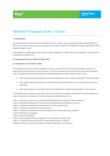
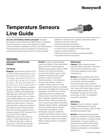
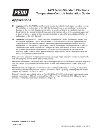
DimensionsFigure 1: A421 Control with Type 1 (NEMA), IP20 enclosure dimensions, in. (mm)Figure 2: A421 Control with Type 4X (NEMA), IP66 enclosure dimensions, in. (mm)Parts includedEach A421 Control includes a Johnson Controls or PENN A99 Series temperature sensor. See A99Series Temperature Sensors, Wiring, and Technical specifications for more information about A99sensors.2A421 Series Standard Electronic Temperature Controls Installation Guide
A99 Series Temperature SensorsThe A421 Controls require an A99 sensor, and each A421 Control includes an A99 sensor. Any A99Series sensor works with the A421 Series Controls. Do not replace an A99 Series sensor with anyother brand, series, or type of temperature sensor. See Ordering information for available A99Series sensor models.You can extend the sensor leads in the field. See Table 1 for information about wire sizes andlengths. On long sensor cable runs, use shielded cable to reduce electromagnetic interference(EMI). Observe EMI best practices when you route sensor leads.Do not immerse the A99 Series sensors in water or any other liquid. The A99 sensors are moisturetolerant and splash resistant but if you immerse the sensor, liquid can enter the sensor probewhere the steel tube meets the wire cable and result in sensor failure, which voids any warranty.In applications where the sensor may be exposed to a lot of moisture, splashing, or rain, mount thesensor in a vertical position with the cable at the bottom routed downward so that moisture candrain away from the stainless steel probe. Use a suitable bulb well for complete fluid immersionapplications. See Ordering information for information about bulb wells.The A99 Series sensors are positive temperature coefficient (PTC) sensors. To test an A99 sensor,disconnect the sensor from the control and measure the resistance between the sensor leads in thefollowing situations: When the temperature at the sensor is 77 F (25 C), the resistance should be 1,035 ohms. When the temperature at the sensor is 32 F (0 C), the resistance should be 855 ohms.See Troubleshooting for more information.When you connect an A99 sensor to a standard A421 Control, the control restricts the range ofusable values from -40 F to 212 F or -40 C to 100 C.See Wiring, Technical specifications, and refer to the A99B Series Temperature Sensors Product/Technical Bulletin (LIT-125186) for more information about A99 Series sensors.MountingObserve the following guidelines when you locate and mount an A421 Control: Make sure that the mounting surface can support the control, DIN rail, mounting hardware, andany user-supplied panel or enclosure. Mount the control in a vertical, upright orientation wherever possible. It is best practice to useDIN rail mounting for type 1 controls. In direct-mount applications, mount the control on a flat and even surface.Mount the control in a location free of corrosive vapors and observe the ambient operatingconditions listed in Technical specifications for the A421 Control and the A99 sensor. Allow sufficient space to connect and route wires, view the LCD, and use the touchpad. Do not mount the control on surfaces that are prone to vibration or in a location where highvoltage relays, motor starters, other sources of electromagnetic emissions, or strong radiofrequency may cause interference. Do not install the control in an airtight enclosure. Do not install heat generating devices with the control in an enclosure that may cause theambient temperature to exceed 150 F (66 C).A421 Series Standard Electronic Temperature Controls Installation Guide3
Mounting a Type 1/IP20 control on DIN rail1.Provide a section of 35 mm DIN rail that is longer than the control width. Mount the DIN rail ina suitable location and use appropriate mounting hardware.2.Clip the control module on the rail, position the module’s upper DIN rail clips on the top rail,and gently snap the lower clips on to the bottom of the rail.Direct-mounting a Type 1/IP20 control to a wall or other flatsurface using the four keyhole slots1.Disconnect the power and remove the enclosure cover. Place the control vertically againstthe wall surface in a suitable location, and mark the keyhole slot locations on the mountingsurface.2.Install appropriate screws or fasteners and leave the screw heads approximately one or twoturns away from flush to the mounting surface.3.Position the control mounting slots over the screw heads, and then tighten the mountingscrews to secure the control to the surface.Note: When you mount the control on an uneven surface, use shims to mount the controlevenly.Additional guidelines for mounting Type 4X/IP66 controlsYou can mount the Type 4X models to flat vertical surfaces using the four holes at the enclosurecorners. Place the control against a flat wall surface in a suitable location, and mark the mountingscrew hole locations on the mounting surface. Use appropriate screws and shims to mount thecontrol evenly on the surface.On Type 4X models, select the knockout for removal. Place a screwdriver blade on the knockoutnear the edge. Apply a sharp blow to the screwdriver handle to loosen the knockout. Be careful notto damage the control’s interior components.The A421 Control's temperature setback (BI) function requires an additional low-voltage, two-wirecable for operation. On Type 4X/IP66 enclosures, you must install a suitable watertight fitting in anavailable knockout to pass the two-wire cable through the enclosure wall.You can rotate the control enclosure base on the Type 4X/IP66 models 180º relative to the controlenclosure cover and LCD, to bring the electrical connection to the top or bottom of the mountedcontrol.Note: Do not twist the wiring harness between the enclosure base and cover more than 180º.4A421 Series Standard Electronic Temperature Controls Installation Guide
WiringWARNINGRisk of Electric ShockDisconnect or isolate all power supplies before making electrical connections. More than onedisconnection or isolation may be required to completely de-energize equipment. Contact withcomponents carrying hazardous voltage can cause electric shock and may result in severe personalinjury or death.AvertissementRisque de décharge électriqueDébrancher ou isoler toute alimentation avant de réaliser un raccordement électrique. Plusieursisolations et débranchements sont peut-être nécessaires pour -couper entièrement l'alimentation del'équipement. Tout contact avec des composants porteurs de tensions dangereuses risque d'entraînerune décharge électrique et de provoquer des blessures graves, voire mortelles.Important: Use copper conductors only. Make all wiring in accordance with local, national,and regional regulations.Important: Do not exceed the A421 Control’s electrical ratings. Exceeding the electrical ratingscan result in permanent damage to the control and void any warranty.Important: Run all low-voltage wiring and cables separate from all high-voltage wiring.It is best practice to use shielded cable for input (sensor) cables that are exposed to highelectromagnetic or radio frequency noise.Important: Electrostatic discharge (ESD) can damage A421 Controls. Use proper electrostaticdischarge precautions during installation and servicing to avoid damaging A421 Controls.Important: Do not connect supply power to the A421 Controls before checking all wireconnections. Short circuits or improperly connected wires can result in damage to the modulesand void any warranty.Important: When you connect an A99 sensor with a shielded cable to an A421 Control,connect the cable shield drain lead to the common (COM) terminal on the sensor and binaryinput terminal block (TB3). Do not connect the shield at any other point along the cable, andisolate and insulate the shield along the entire length of the sensor cable. If you connect acable shield at more than one point, transient currents can flow through the sensor cableshield and cause erratic control operation.Observe the wire size restrictions listed in Table 2 and the electrical ratings listed in Technicalspecifications.Observe the following guidelines, procedures, and illustrations when you wire an A421 SeriesControl and A99 Series sensor. Select the appropriate A99 sensors for the ambient operating range that the A421 Controlmonitors and controls, as shown in Table 7. See Technical specifications for more information. Keep the sensor leads as short as possible in your application. The additional resistance in longA421 Series Standard Electronic Temperature Controls Installation Guide5
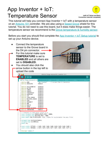
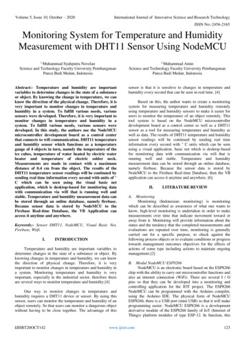
sensor cables creates an offset between the actual temperature and the displayed temperature.See Table 1 when you extend sensor leads. A99 sensors are not polarity specific. You can connect either lead to the SEN or COM terminals. It is best practice to use 22 AWG, stranded, twisted-pair cable with a shield to extend sensor cableruns.Table 1: Maximum sensor cable lengths and wire sizesMaximum sensor cable length16 AWG500 ft (150 m)18 AWG300 ft (100 m)20 AWG200 ft (60 m)22 AWG125 ft (40 m)11Wire gauge1The maximum sensor cable lengths have less than 1 F (0.6 C) error between the temperature sensed at the A99 sensorand the temperature displayed on the LCD.TB2 Terminal Block and SPDT relay outputThe terminals LC, LNO, and LNC on the TB2 terminal block connect to an SPDT dry-contact relay inthe A421 Control (Figure 3). The control does not provide any internal power to the TB2 terminalsor relay contacts. The A421 Control energizes and de-energizes the relay to open and close thecontacts based on the On/OFF temperature values. Relay De-energized (Off) LC open to LNO as shown in Figure 3, and the relay status LED is off Relay Energized (On) LC closed to LNO and the relay status LED is onFigure 3: TB2 Terminal Block showing connections to the internal SPDT relayFigure 4 shows how to wire the A421 Control to use the same power source that powers thecontrolled equipment to also power the A421 Control.You can also provide an independent power source for the A421 Control on the TB1 terminals andthen wire the TB2 relay terminals to a separate power source to switch and power the controlledequipment circuit.6A421 Series Standard Electronic Temperature Controls Installation Guide
Figure 4: Wiring the A421 Series Controls using the same power sourceto power the control operation and power the controlled equipmentTable 2: A421 Control wiring terminals and wire size informationTerminalblockLabel Description, function, and requirementsWire sizesTB124 VACModelsLNLow-voltage 24 VAC control power (common): Connect the24 VAC supply power to operate the control.28 AWG toTB1120/240VACModelsLNLine-voltage power source (common): Connect the neutralwire for 120 VAC supply power applications. Connect theL1 supply power lead for all 208/240 VAC supply powerapplications.28 AWG to24 V12 AWGLow-voltage 24 VAC control power (hot): Connect 24 VACsupply power to operate the control (via jumper from LC in 0.08 mm² toFigure 4).4.0 mm²120 V Line-voltage 120 VAC control power (hot): Connect the120 VAC supply power (hot) for 120 VAC supply powerapplications through the jumper from LC. (Figure 4).12 AWG0.08 mm² to4.0 mm²240 V Line-voltage 240 VAC control power (L2) terminal: Connectthe L2 supply power connection for 208/240 VAC supplypower applications through the jumper from LC. (Figure 4).TB2LCLNOLine-voltage SPDT relay common contact: Connects powersupply to power the controlled load. Connect 24 VAC(hot) for 24 VAC applications; 120 VAC (hot) for 120 VACapplications’ and L2 for 208/240 VAC applications.Line-voltage SPDT relay normally open contact: Connectscontrolled equipment to the line-voltage normally open(LNO) contact on the SPDT relay. When LC is closed toLNO, the relay is energized and the green LED is on. TheLNO terminal typically provides power to the controlledequipment in cooling and heating applications.28 AWG to12 AWG0.08 mm² to4.0 mm²A421 Series Standard Electronic Temperature Controls Installation Guide7
Table 2: A421 Control wiring terminals and wire size informationTerminalblockTB3Label Description, function, and requirementsWire sizesLNCLine-voltage SPDT relay normally closed contact: Connectscontrolled equipment to the line-voltage normally closed(LNC) contact on the SPDT relay. When LC is closed to LNC,the relay is de-energized and the green LED is off. The LNCterminal is not typically wired to the controlled equipment.BINDetects a switch closure between the BIN and COMterminals and enables the selected temperature setback(tSb) value.COMConnects the low-voltage common from the sensor andbinary input.SENConnects the low-voltage input signal wire from controlsensors.22 AWG (0.34mm²) stranded,shielded cableReplacing an A419 Control with an A421 Control: Terminallocations and labelsThe A421 Series Electronic Temperature Controls are the next generation of the A419 SeriesElectronic Temperature Controls.If you need to replace an A419 Control with an A421 Control, be sure to note that wiring terminalson the TB1 and TB2 terminal blocks on A421 Controls are in different positions and have differentterminal labels from the wiring terminals on the A419 Controls. Table 3 provides a cross-referencefor matching the terminal labels on A419 Controls to the terminal labels on A421 Controls.Note: The low-voltage signal terminals on the TB3 terminal block are labeled the same on bothA419 Controls and A421 Controls.See Figure 4 for terminal block and terminal positions on the A421 Control.Table 3: A419 and A421 wiring terminal labelsTerminal blockA419 Terminal labelA421 Terminal labelTB1(24 VAC)T1LNT224VTB1(120/240 VAC)120120V240240VAC COMLNCLCNOLNONCLNCTB2(All Voltages)Setup and adjustmentsThe front panel of the A421 Series Electronic Temperature Control has an LCD and a three-button UI(Figure 5).8A421 Series Standard Electronic Temperature Controls Installation Guide
Figure 5: A421 Control front panel with LCD and three-button UILCDThe A421 Series Control has a backlit LCD screen (Figure 5). You can adjust the LCD brightness.During normal operation, the LCD displays the Main screen, which provides the followinginformation: Temperature sensed at the A99 sensor Selected temperature units ( F or C) Mode of operation (Flame Heating mode, Snowflake Cooling mode) Binary Input status (BIN) when a user-supplied binary input (switch) is connected and closed toenable the temperature setback feature.During setup and adjustment, the LCD displays the parameter code screens and the parametervalue screens. See the A421 Control parameter setup menus for more information.Three-button touchpadThe touchpad has three buttons for setup and adjustment of the A421 Control (Figure 5). SeeNavigating the Basic and Advanced menus for more information about the three-button touchpad.Relay status LEDThe green LED on the front panel illuminates when the SPDT output relay is energized and the LCand LNO contacts are closed. See Figure 5.Parameter codes and modes of operationRelay Off temperature (OFF)Select the temperature at which the output relay de-energizes, the LC to LNO relay contactsopen (cutout), and the green LED goes off. The range of usable temperature values is -40 Fto 212 F (-40 C to 100 C) in 1 increments.A421 Series Standard Electronic Temperature Controls Installation Guide9
Relay On temperature (On)Select the temperature at which the output relay energizes, the LC to LNO relay contactsclose (cut in), and the green LED lights. The range of usable temperature values is -40 F to212 F (-40 C to 100 C) in 1 increments.Heating or Cooling mode of operationWhen you select your required On and OFF values, the control automatically determines themode of operation and displays the proper mode icon on the Main screen.Note: The A421 Series controls do not have jumpers for setting up the heating or coolingmode.The heating or cooling mode is determined by the On and OFF value relationship as follows: OFF On Heating mode Flame icon OFF On Cooling mode Snowflake iconImportant: During normal operation, adjusting just the On value or just the OFFvalue on the A421 control changes the differential between On and OFF, and canpotentially change the mode of operation from heating to cooling or cooling to heating.To maintain a constant differential between on and off, you must adjust both the onand off values by an equal number of degrees, or set up the control in the RestrictedAdjustment mode. See Restricting User Adjustment.Anti-short cycle delay (ASd)Select the minimum time that the output relay remains off (de-energized) before the nexton-cycle can start. The ASd interval overrides any load demand (On) and does not allow theoutput relay to go on until the selected ASd interval has elapsed. See the following figure.Figure 6: Anti-short cycle delayAnti-short cycle delay is typically used for refrigeration applications so that the systempressure can equalize before restarting the compressor.Note: When the ASd value is greater than 0, the delay interval initiates every time that theA421 Control is powers on and every time that an off-cycle begins. When the ASd intervalis activated, the temperature sensed at the A99 sensor and the parameter code ASd flashalternately on the LCD. You can set the ASd interval from from 0 minutes to 12 minutes, in 1minute increments.Sensor Failure mode (SF)Select whether the control’s output relay operates as energized or de-energized in the eventof a sensor or sensor wiring failure. When the control detects a sensor circuit failure, the10A421 Series Standard Electronic Temperature Controls Installation Guide
output relay operates in the selected sensor failure mode. The LCD flashes SF and OP if thesensor circuit is open or SF and SH if the sensor circuit is shorted.Temperature Units (Un)Select the preferred temperature scale for your application. Select either the Fahrenheit ( F)or Celsius ( C) temperature scale.Note: After you change the temperature units value (Un), confirm that the temperature valuesfor the other parameter codes are still correct for your application.Low Temperature Stop (LtS)Select the lowest temperature value that the On/OFF control band can be adjusted to whencontrol adjustment is restricted.High Temperature Stop (HtS)Select the highest temperature value that the On/OFF control band can be adjusted to whencontrol adjustment is restricted.Restricted Adjustment modeThe HtS and LtS values define the restricted adjustment temperature range and areenforced only when the A421 control is set to the restricted adjustment mode (Figure 9). SeeRestricting user adjustment.Note: It is best practice to leave HtS and LtS at their default values, unless you intend to usethe restricted adjustment mode.Note: If you use the Temperature Setback feature in the Restricted Adjustment Mode, theeffective On and OFF setback values (On tBs and OFF tBs) can be greater than the selectedHtS value or less than the selected LtS value.Temperature Setback (tSb)Select a temperature value for setting back the On and OFF temperature values. Whena user-supplied switch between the BIN and COM terminals closes, note the followingchanges: The Main screen displays BIN in the upper-right corner of the LCD. The temperature setback feature is enabled and the control uses the effective On and OFFsetback values (On tSb and OFF tSb) to control the relay.Note: The control displays only the original On and OFF values in both the normal and setbackmodes. The effective setback On and OFF values (On tSb and OFF tSb) never display on thecontrol LCD.The temperature setback adjustment range is from -50 F to 50 F (-30 C to 30 C). Typically,heating applications require a negative temperature setback (tSb) value, and coolingapplications require a positive value.Sensor Offset Adjustment (So)Sensor offset allows you to compensate for any difference between the displayedtemperature value and the temperature sensed at the A99 sensor. Select a temperaturevalue to offset the temperature displayed on the LCD from the temperature sensed at thesensor. The sensor offset adjustment range is from -5 F to 5 F (-3 C to 3 C) in 1 increments.A421 Series Standard Electronic Temperature Controls Installation Guide11
Backlight Brightness Level (bLL)The backlight brightness level feature allows you to adjust the LCD backlight intensity. Atlevel 0 the backlight is off. Level 10 is the brightest backlight setting and the system default.The selected backlight brightness level is applied to the LCD during normal operation.When you enter the programming menus to set up the control or press any key, the LCDautomatically goes to the brightest level. If you do not press a key for 30 seconds, the mainscreen displays and the backlight setting reverts to the selected brightness level.Table 4: Standard parameter setup codes, descriptions, range of values, and default valuesParameter description (menu)UnTemperature Units (Advanced only)ºF or ºCºFOFFRelay Off Temperature (Basic,Advanced, and Restricted)-40ºF to 212ºF25ºFRelay On Temperature (Basic andAdvanced)-40ºF to 212ºFASdAnti-Short Cycle Delay (Basic andAdvanced)0 minutes to 12 minutes 1 minutetSbTemperature Setback (Advancedonly)-50ºF to 50ºFOnRange of usable values Factory default1Parametercodevalue1(-40ºC to 100ºC)30ºF(-40ºC to 100ºC)0ºF(-30ºC to 30ºC)SoSensor Offset Adjustment (Advanced -5ºF to 5ºFonly)(-3ºC to 3ºC)0ºFHtSHigh Temperature Stop (Advancedonly)-40ºF to 212ºF212ºFLow Temperature Stop (Advancedonly)-40ºF to 212ºFSFSensor Failure Action (Basic andAdvanced)0 output relay deenergized1 output relayenergizedbLLLCD Backlight Brightness LevelAdjustment (Advanced only)0 to 10; 0 backlight off, 10 (brightest10 brightest backlight backlight)settingLtS1(-40ºC to 100ºC)-40ºF(-40ºC to 100ºC)1 output relayenergizedThe default values for general application A421 models are shown. OEM A421 models may have different default values.A421 Control parameter setup menusThe A421 Temperature Controls have a Basic and an Advanced setup menu. You can scroll throughthe parameter setup codes, view and edit parameter values, and set up your control for yourapplication requirement. The control also has a Restricted adjustment menu. See Restricting useradjustment for more information.12A421 Series Standard Electronic Temperature Controls Installation Guide
Note: The A421 Control retains a copy of the saved parameter values in memory. When youchange and save a new value, the new value immediately overwrites the previous value andsaves to memory. In the event of a power failure, brown out, or when you disconnect powerfrom the control, all of the current parameter values in memory are retained. Reconnectingpower to the control restores all of the saved values.Navigating the Basic and Advanced menusThe A421 Control buttons and display operate the same way in Basic and Advanced menus. You canobserve the following behavior in any parameter code screen:The parameter code flashes on and off. To navigate through all of the parameter code screens, press Down or Up. To exit either menu and return to the Main screen, press Down and Up simultaneously.You can perform the following actions in any parameter code screen:The parameter value flashes on and off. To scroll through all of the available parameter values for the associated parameter code, pressDown or Up. With the preferred parameter value displayed, press MENU to save the value and go to the nextparameter code screen.Note: If you do not press MENU to save a new value, the control reverts to the last savedvalue.After 30 seconds of inactivity while in any screen, the control reverts to the Main screen.Basic menuUse the Basic menu to quickly edit the On and OFF temperature values, as well as the Sensor FailureMode (SF) and the Anti-Short Cycle Delay (ASd) value.See Parameter codes and modes of operation and Table 4 for more information about parametercodes, usable parameter values, and default values.A421 Series Standard Electronic Temperature Controls Installation Guide13
Figure 7: Navigating the Basic menuViewing and changing values in the Basic menuTo access the Basic menu and view and change the Basic parameter values, complete the followingsteps:1.On the Main screen, press MENU. The LCD displays OFF, which is the first parameter codescreen displayed in the Basic menu.2.To scroll through all of the basic parameter codes and display the preferred code, press Downor Up.3.With the preferred parameter code displayed, press MENU to display the current parametervalue for the code.4.With the current parameter value displayed, press Down or Up to scroll through all of theparameter’s usable values and display the preferred value.5.With the preferred parameter value displayed, press MENU to save the displayed value and goto the next parameter code.6.To exit the Basic menu and go to the Advanced menu, simultaneously press and hold Down orUp for 5 seconds.Advanced menuYou can use the Advanced menu to change the parameter values in the Basic menu and theparameter values for the following advanced parameter codes: Temperature Units (Un) Temperature Setback (tSb)14A421 Series Standard Electronic Temperature Controls Installation Guide
Sensor Offset (So) High Temperature Setpoint Stop (HtS) Low Temperature Setpoint Stop (LtS) Backlight Level (bLL)See Parameter codes and modes of operation and Table 4 for more information about parametercodes, usable parameter values, and default values.Figure 8: Navigating the Advanced menuViewing and changing values in the Advanced menuTo access the Advanced menu and view and change the parameter values, complete the followingsteps:1.On the Main screen, press and hold Down or Up simultaneously for 5 seconds. Un displays onthe LCD, which is the first parameter code screen displayed in the Advanced menu.2.To scroll through all of the advanced parameter codes and display the preferred code, pressDown or Up3.With the preferred parameter code displayed, press MENU to display the current parametervalue for the code.A421 Series Standard Electronic Temperature Controls Installation Guide15
4.With the current parameter value displayed, press Down or Up to scroll through all of theparameter code’s usable values and display the preferred value.5.With the preferred parameter value displayed, press MENU to save the displayed value and goto the next parameter code.Restricting user adjustmentYou can restrict user adjustment of the A421 Control to the OFF value control band only and limitthe range of this value (Figure 9).To set the A421 Control the restricted adjustment mode, position the jumper located on the circuitboard next to the TB3 terminal block. See Setting the control to Restricted Adjustment mode.Note: Setting the A421 Control up in the Restricted mode prevents casual users from overadjusting the control in your application, or from inadvertently changing the mode ofoperation from cooling to heating or heating to cooling by over-adjusting the On value or OFFvalue.When the A421 Control is set up in the restricted adjustment mode, the controller enforces thefollowing behavior: The selected HtS and LtS values define the restricted temperature adjustment range. The On and OFF values define the control band differential, and the control band between Onand OFF remains fixed and not adjustable. Only the OFF value can be adjusted, the control band remains fixed, and the On valueautomatically shifts equal to the OFF value adjustment. The OFF value can only be adjusted to values that maintain the entire control band within therestricted temperature adjustment range defined by HtS and LtS. See Figure 9. The basic and advanced menus are not available. Only the Restricted Adjustment mode menu isavailable and only the
A421 Controls have simple on and off temperature settings for heating or cooling, an adjustable anti-short cycle delay, temperature setback, and sensor offset capability. The temperature control range is -40 F to 212 F or -40 C to 100 C. The A421 Controls are available either in Type 1 (NEMA), IP20 (CE), high-impact plastic enclosures