Transcription
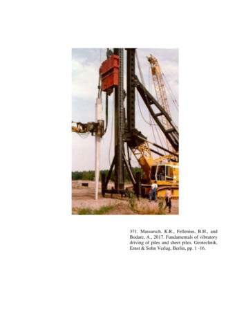
371. Massarsch, K.R., Fellenius, B.H., andBodare, A., 2017. Fundamentals of vibratorydriving of piles and sheet piles. Geotechnik,Ernst & Sohn Verlag, Berlin, pp. 1 -16.
FachthemenK. Rainer MassarschBengt H. FelleniusAnders BodareDOI: 10.1002/gete.201600018Fundamentals of the vibratory driving of pilesand sheet pilesVibratory driving is a common method for installing or extractingpiles and sheet piles as well as for deep vibratory compaction.The most important parameters are vibration frequency, vibrationamplitude and eccentric moment. These parameters govern vibratory driving and, in particular, the soil resistance at the toeand along the shaft of a pile. Pile driving causes oscillating horizontal ground vibrations in coarse-grained soils. It can be shownthat these horizontal vibrations reduce the shaft resistance during driving. The process results in a permanent increase in thehorizontal effective stress, which causes arching around the vibrated pile. The increase in horizontal effective stress is alsoimportant for deep vibratory compaction. The resonance frequency of the vibrator-pile-soil system significantly affects pile penetration and the emission of ground vibrations. At resonance, thevertical vibration velocity in the soil reaches a maximum and pilepenetration becomes very slow, whereas beyond resonance, thevibration velocity decreases and the pile penetration speed ishigh. Field monitoring of the vibratory driving process can beused to optimize vibratory pile driving, as examples have shown.A new concept is proposed in which the driveability can be determined from a correlation between penetration resistancemeasurements (blows/depth) and penetration speed. The validityof the concept is demonstrated by a case history and project references.Grundlagen des Vibrationsrammens von Pfählen und Spundbohlen. Vibrationsrammen ist ein effektives Verfahren zum Einbringen oder Ziehen von Spundwänden und Pfählen sowie für dieTiefenverdichtung. Die wichtigsten Parameter sind Schwingfrequenz, Schwingamplitude und statisches Moment. Diese Parameter bestimmenden den Vibrationsvorgang und, insbesondere,den Bodenwiderstand an der Pfahlspitze sowie längs des Pfahlmantels. Das Vibrationsrammen verursacht horizontale Bodenschwingungen in grobkörnigen Böden die den Bodenwiderstandwährend des Ramm- oder Ziehvorganges reduzieren. Durch dasVibrationsrammen wird außerdem die horizontale Effektivspannung dauerhaft erhöht und verursacht eine Gewölbebildung umden Pfahl. Die Erhöhung der horizontalen Effektivspannung istauch wichtig bei der Tiefenverdichtung mittels Vibratoren. DieResonanzfrequenz des Vibrator-Pfahl-Boden Systems ist einwichtiger Faktor der den Eindringvorgang von Pfählen undSpundbohlen, sowie die Ausbreitung von Bodenschwingungenbeeinflusst. Bei Resonanz erreicht die vertikale Schwingungsgeschwindigkeit im Boden ein Maximum und das Eindringen desPfahls in den Boden verlangsamt sich markant. Beim Einvibrierenoder Ziehen von Pfählen deutlich über der Resonanzfrequenznehmen die Bodenschwingungen ab und die Eindringgeschwindigkeit von Pfählen oder Spundbohlen erhöht sich. Durch dasMessen verschiedener Schwingparameter kann der Rammvorgang optimiert werden. Ein neues Konzept zur Beurteilung derRammbarkeit von Pfählen wird vorgestellt, das von der Beziehungzwischen Sondierwiderstand und Eindringgeschwindigkeit desPfahls ausgeht.1IntroductionVibrators play an important role in many constructionprocesses and, in particular, are used for the installationand/or extraction of piles and sheet piles. In many countries, and in Europe especially, new innovative vibratorydriving equipment – hydraulic vibrators in particular – hasbeen developed, such as vibrators with variable operatingfrequency and variable amplitude (eccentric moment). Vibrators can either be suspended from a crane or guided byleads depending on the specific application. The operation of modern hydraulic vibrators can be controlled,monitored and documented during all phases of operation.The geotechnical literature describes many successful applications of vibrators for driving piles or sheet pilesor installing casings. Vibratory driving can often achievehigh production rates with minimal environmental impact. However, vibratory driving should be chosen withcareful consideration for the project-specific conditions,such as the geotechnical and hydrogeological situation,environmental considerations, etc. Otherwise, environmental effects (such as ground vibrations) can have negative consequences. The selection of vibrators for specificapplications is frequently based on empirical rules. Unfortunately, many foundation companies leave the choice ofvibrator type and the selection of operating parameters tomechanical engineers, who often have insufficient understanding of fundamental geotechnical principles. Whenusing vibrators to install piles, the following three aspectsneed to be addressed:– Driveability: Select appropriate vibrator system andoperation to assure efficient performance.– Bearing capacity: Verify that the required bearing capacity can be achieved.– Environmental impact: Minimize ground vibrationsand/or noise.The objective of this paper is to show that the three aspects mentioned are closely linked and one aspect cannot Ernst & Sohn Verlag für Architektur und technische Wissenschaften GmbH & Co. KG, Berlin · geotechnik (2017)1
K. R. Massarsch/B. H. Fellenius/A. Bodare · Fundamentals of the vibratory driving of piles and sheet pilesbe addressed without considering the others. The paperfocuses on the analysis of the pile/sheet pile driving process and on how to optimize the installation process byvarying the machine parameters during installation or extraction. Consideration is also given to the important, butoften neglected, aspect that ground vibrations generatedduring vibratory driving in coarse-grained soils also causea permanent increase in horizontal stress and induce preconsolidation. Such stress changes affect the static bearing capacity of piles as well as the compaction effect insands. Although of great practical importance, a detaileddiscussion of the environmental aspects of vibratory driving (ground vibrations and permanent soil displacement)are beyond the scope of this paper. Static soil displacements due to the installation of piles have been describedin [1]. Vibrations caused by pile driving have been discussed in [2].2Vibratory drivingModern vibrators can be controlled and adapted to achieveoptimal performance. In the following, the term pile willbe used but the concepts apply also to the driving of sheetpiles, casings or compaction probes. An important advantage of modern vibrators is that machine parameters canbe varied to achieve efficient driving or compaction. Vibratory excitation affects a pile in a different way to impact driving. In the case of vibratory driving, the pile isrigidly connected to the vibrator, resulting in minimal energy loss as energy is transferred from vibrator to pile. Thevibration frequency is relatively low, typically below 40 Hz(2400 rpm). Thus, the wavelength propagating down thepile is much longer than in the case of impact driving. Thepile is kept in an oscillating motion during the entire vibratory driving process. It is generally recognized thatvibratory driving is most efficient in coarse-grained (frictional) soil and less efficient in fine-grained (cohesive) soil.Modern vibrators are hydraulically driven, which allows continuous variation of the vibrator frequency duringoperation. The vertical oscillation of the vibrator is generated by counter-rotating eccentric masses. The peak valueof the centrifugal force Fv acting in the vertical directiondepends on the eccentric moment Me and on the circularfrequency w ( 2pf) of the rotating eccentric masses:FV Meω 2 (1)The centrifugal force of many modern vibrators with variable eccentric moment and frequency can be adjustedcontinuously during operation. The displacement amplitude s and the centrifugal force Fv determine the drivingability of the vibrator. For a vibrator suspended above theground surface, the vertical displacement amplitude, s,(single amplitude) can be determined from the followingrelationship:s Me (2)mtThe “total dynamic mass” mt is the sum of all the massesthat need to be accelerated by the vibrator. This includesthe vibrator, the pile and the vibrator clamp. Note that2geotechnik (2017)most equipment manufacturers express the displacementamplitude as peak-to-peak (“double”) amplitude. FromEq. (2) it can be appreciated that the displacement amplitude s is independent of the vibration frequency, f. In order to maximize the displacement amplitude, the total dynamic mass, mt should be kept as small as possible. Vibrators with variable eccentric moment allow the machineoperator to start up and shut down the vibrator at zerovibration amplitude, thus reducing the risk of vibrationamplification due to resonance.3Amplitude-dependent pile-soil interactionIn addition to lower losses when transferring the energy tothe pile and the longer length of the force wave, there arealso other fundamental differences between the pile-soilinteraction of impact-driven piles and that of vibratory driven piles, as discussed in the following.3.1Pile shaft resistanceIn the case of impact driving, it is necessary to overcomethe inertia of the pile and the shear resistance along thepile-soil interface. At the end of each impact, the pilepene tration slows down and static conditions return alongthe pile. In the case of vibratory driving, the pile is keptoscillating axially (usually vertically) during the entiredriving phase. Several hypotheses have been proposed inorder to explain why vibratory driving is more efficientthan impact driving in coarse-grained soil. Examples ofpossible causes of reduced shaft friction (permanent and/or temporary) mentioned in the geotechnical literature are“rolling friction”, “liquefaction”, and “material degradation”. However, these terms are mainly descriptive andtherefore difficult to quantify. A more rational concept isneeded, which can be based on the cyclic forces generatedduring vibratory driving. Field measurements of groundvibrations during vibratory driving have shown that thevertically oscillating force creates – due to shaft friction –a horizontally oscillating force. As this horizontal force isdirected away from the pile shaft, it reduces the shear resistance with each downward movement [3]. This phenomenon, which is confirmed by field measurements presented below, is believed to be the main reason for enhanced pile penetration in coarse-grained soil.In fine-grained (cohesive) soils, shaft resistance decreases due to strain and the number of vibration cycles(remoulding) occurring when the relative displacementbetween the pile and the soil exceeds about 5–10 mm. Themagnitude of the eccentric moment of the vibrator istherefore important for the vibratory driving of piles incohesive soils as it determines the relative displacementbetween pile and soil, see Eq. (2).3.2Pile toe resistanceThe mechanism of pile-soil interaction during vibratorydriving has been studied by several investigators [4], [5],[6]. The following simplified model illustrates the motionof the pile toe during one vibration cycle [7]. Fig. 1 showsthe toe force FT versus penetration z. At (1), the pile hascompleted a downward motion and starts the upward re-
K. R. Massarsch/B. H. Fellenius/A. Bodare · Fundamentals of the vibratory driving of piles and sheet pilesdriving also has an effect on toe bearing. If the vibrationamplitude (and therefore the toe-soil separation (2)–(3)) issmall during the final phase of pile installation, soil decompression below the toe will be low. For this reason, itis advantageous to reduce the vibration (displacement)amplitude gradually over a minute or two at the end ofdriving toe-bearing piles, as opposed to turning off the vibrator suddenly.3.3Fig. 1. Simplified model of pile toe-soil interaction duringvibratory driving, after [7]Bild 1. Vereinfachtes Model der Wechselwirkung zwischenPfahlspitze und Boden beim Vibrationsrammen, nach [7]bound movement of the cycle. At first, the soil below thepile toe will follow the upward movement in an elastic response. At (2), the contact force between the pile toe andthe soil is reduced to zero. If the upward movement of thepile stops at (2), the pile toe will not become separatedfrom the underlying soil. This will be the case if the displacement amplitude of the pile is small. If the upwardmovement of the pile continues, the pile toe separatesfrom the soil. During this phase, a void can be generatedbetween the soil and the pile toe, causing suction (“cavitation”) between the pile toe and the soil below the toe. Thisphase of vibratory driving is important as this can result inremoulding and/or loosening of the soil below the piletoe. When the oscillation cycle is reversed (3), the pileagain moves downward and, after some movement, regains contact with the soil (4). The toe resistance duringthe following cycle (1′) depends on the effect the previousvibration cycle had on the soil below the toe.The variation in the toe resistance during vibratorydriving is fundamentally different to that of impact driving. In the case of impact driving, the pile toe will remainin contact with the underlying soil. In contrast, in vibratory driving, the pile toe can separate from the underlyingsoil. As mentioned, the separation depends on the displacement amplitude (2)–(3) and the remoulding/suctioneffect during this phase of vibratory driving. If there is little or no separation between the pile toe and the underlying soil, the resistance to downward movement (penetration) will be approximately similar to that generated byimpact driving. It is apparent that the vibration amplitudeinfluences the toe/soil resistance during vibratory driving.The mode of toe penetration during vibratory and impactHorizontal ground vibrationsA comprehensive test programme in [8] investigatedwhether horizontally oscillating waves occur in the soilduring vibratory driving. An approx. 12 m long steel probewas vibrated at a frequency of 27 Hz into a deposit ofdredged sand. The probe depth was 7 m. The vibratorused was a Müller MS 200 HF (centrifugal force: 4000 kN,max. eccentric moment: 1900 Nm) with variable frequency (0–30 Hz). Geophones were installed at different distances from the pile. Fig. 2 shows horizontal ground vibrations (velocity vs. time) measured at four geophonesplaced 3 m from the pile – on the ground surface and atdepths of 1.65, 3.55 and 5.05 m. It is apparent that the vibration velocity is approximately the same at all levels(indicating that the vertically oscillating probe is thesource of vibrations). The vibration frequency was 27 Hz,identical to the operating frequency of the vibrator. (Thedistance between horizontal grid-lines in Fig. 3 is 50 mm/s).Fig. 2 shows that in coarse-grained soil, a verticallyoscillating probe generates not only vertical, but also horizontal vibrations – and these can be quite strong. Theymanifest themselves as a horizontally oscillating wavefield, which builds up horizontal stresses as a result ofcontinuous cyclic loading. The pulsating, horizontal stresses reach their maximum at the end of each downward(and upward) cycle. The soil is pushed away from the oscillating probe, which is compressed horizontally, building up high horizontal effective stresses.3.4Implications of horizontal ground vibrationsDuring vibratory driving in coarse-grained soil, the shaftresistance of a pile will be reduced due to the horizontallyoscillating stress field. The horizontal stresses are directedaway from the pile and can cause arching in a cylindricalzone surrounding the pile. However, this arching effectwill disappear when piles are installed in a group due tothe fact that each pile driven will “disturb” the arching effect that has built up around the pile driven previously.Moreover, observations in soil compaction projects haveshown that horizontal stresses will equalize to an averagevalue over time. It is therefore difficult to estimate theshaft resistance of a vibratory driven pile.Horizontal ground vibrations are also importantwhen probes or piles are used for deep vibratory compaction of coarse-grained soil. The primary objective is to increase soil stiffness and strength. However, as statedabove, vibratory compaction results in a permanent increase in horizontal stresses. The increase in lateral effective stress following vibratory compaction has been measured using field investigation devices, such as pressuremeters [9], dilatometers [10] and cone penetrometers [11].geotechnik (2017)3
K. R. Massarsch/B. H. Fellenius/A. Bodare · Fundamentals of the vibratory driving of piles and sheet pilesFig. 2. Horizontal ground vibrations measured at 3 m from compaction probe oscillating at 27 Hz; penetration depth ofpile 7 m, taken from [8]Bild 2. Horizontale Bodenschwingungen, gemessen in 3 m Abstand von der Verdichtungsstange, bei einer Schwingungs frequenz von 27 Hz. Die Eindringtiefe des Pfahls war 7 m, nach [8]A permanent increase in horizontal stress due to vibratory compaction by surface rollers was investigated in[12], which describes a significant increase in horizontalstress (up to the passive earth stress). Ref. [13] confirmsthat vibratory compaction of coarse-grained soil, in a process of load application and removal, can result in a significant increase in permanent residual horizontal stress.The researchers developed a hysteric model for multi-cyclic K0-loading that can be used to predict the increase inlateral effective stress. They concluded that compactionrepresents a form of preconsolidation, similar to the application and removal of a superficial static surchargestress.Fig. 3 shows a representative CPT from the test site.The left diagram shows the cone stress and the right diagram the sleeve friction, before and after soil densification. The vibratory compaction resulted in a permanentincrease in cone stress and sleeve friction. The cone stressFig. 3. Filtered average cone stress and sleeve friction values before and after compaction, taken from [3]Bild 3. Gefilterte Mittelwerte des Spitzenwiderstandes und der Mantelreibung, vor und nach der Verdichtung, von [3]4geotechnik (2017)
K. R. Massarsch/B. H. Fellenius/A. Bodare · Fundamentals of the vibratory driving of piles and sheet pileswas raised from approx. 5 to 10 MPa and the sleeve friction, which is directly affected by horizontal effectivestress, increased from 10 kPa to a maximum of 45 kPa,corresponding to a factor of 2 to 3. Such a change in sleevefriction is related to a change in horizontal effective stress.The implications of a permanent increase in horizontal stress due to vibratory compaction are important asthese change the coefficient of lateral earth pressure atrest. A concept was presented in [11] to show how thepreconsolidation margin (or overconsolidation ratio,OCR) can be determined from CPT soundings.4Frequency-dependent pile-soil interactionOne important parameter that affects the penetration resistance during pile driving and vibratory compaction isthe operating frequency of the vibrator. Experience from alarge number of soil compaction projects – and especiallywhere the resonance compaction system was used –demonstrates the importance of vibration frequency whencompacting coarse-grained soil. In order to analyse theoretically the interaction between a vertically oscillating element in an elastic medium, ref. [14] used a two-degreesof-freedom (2DOF) system. The mass of a pile mp interactswith the surrounding soil ms through springs kT and kMand dampers dT and dM, as shown in Fig. 4. Note, however, that the objective of this analysis was to study the interaction of a pile with the soil at resonance, i.e. when thepile is vibrating in phase with the surrounding soil, andthat this model is not applicable to the pile penetrationphase (elasto-plastic conditions). Different conditions apply during pile penetration.The resistance of the soil along the pile consists oftwo components: pile shaft resistance and pile toe resistance. The system denoted “P” models the soil in contactwith the pile. The system denoted “S” models the soil, lying further away but still participating in the dynamic action. The pile is regarded as rigid because the shear modulus of a steel or concrete element is much higher than thatof the soil (by about 103). The total resistance between thesoil and the pile (spring kP and damper dP) then consistsof the sum of the shaft (mantle) and toe resistances kMand kT respectively. The vertical displacements of the pileand the soil are denoted uP and uS respectively.kP k T kM and dP d T dM (3)The force amplitude function Fp0 can be an arbitrary function of the driving frequency w (2pf). In practice, two functions dominate: a constant, frequency-independent, amplitude function and a quadratic function that is a consequence of excitation obtained from the rotating masses.Fp0 mee ω 2 (4)where me is the eccentric mass and e the eccentric distance. Two equations of motion, expressed in displacements, velocities and accelerations as functions of time,can be obtained according to Newton’s second law. Thetheoretical model assumes an elastic response of the soil,i.e. a soil modulus (and thus wave speed) independent ofstrain (displacement). As will be shown below, this as-Fig. 4. One-dimensional soil model with two degrees of freedom for analysing pile-soil interaction [14]Bild 4. Eindimensionales Bodenmodell mit zwei Freiheitsgraden zur Analyse des Zusammenwirkens von Pfahl undBoden [14]sumption is only correct at or near resonance, when thepile element interacts with the surrounding soil.During the penetration phase, the pile moves relativeto the soil and the soil at the pile interface is in a plasticstate (failure, i.e. a plastic state is, by definition, requiredto allow the pile to penetrate into the soil). The derivationof the theoretical solution to this pile-soil interactionproblem is too complex to be included in this paper; fordetails see [14]. The following example illustrates the application of the theoretical model with the aim of demonstrating the influence of vibration frequency on the movement of the pile and the surrounding soil. Table 1 showsthe parameters assumed in the analysis.The first important result of the analysis is the displacement response of the vibrating pile uP as a functionof vibration frequency (real, imaginary and absolute values). For the case shown in Fig. 5, the values of eccentricmoment and shear wave speed were assumed to be Me 10 kgm and cS 225 m/s. Ref. [14] showed that a clearresonance peak of the vibrator-pile-soil system occurs,Table 1. Parameters assumed in dynamic pile-soil responseanalysisTabelle 1. Bei der dynamische Pfahl-Boden Response-Analyse angenommene ParameterEccentric momentMe10kgmTotal density of soilr2000kg/m3Poisson’s ration0.33–Side length of pileb600mmMass of vibrator incl. clampmVC3500kggeotechnik (2017)5
K. R. Massarsch/B. H. Fellenius/A. Bodare · Fundamentals of the vibratory driving of piles and sheet pilesFig. 5. Displacement amplitude uP of a pile as a function offrequency; resonance occurs at 23 HzBild 5. Verschiebungsamplitude uP des Pfahls in Abhängigkeit von der Frequenz. Resonanz bei 23 Hzwith an amplification factor of about seven for the absolute amplitude at the resonance frequency.The next step in the analysis was to determine therelative movement of the pile against the soil, especially inthe frequency range close to resonance. Fig. 6 shows theratio of absolute displacement of the soil and the pile uS/uP. This ratio can be interpreted as a transfer function ofvibration energy from the pile to the surrounding soil. Theimportant conclusion from Fig. 6 is that, below the resonance frequency, the relative displacement between thepile and the soil is very small (uS/uP 0.36) and the pileand the soil move almost in phase, displaying only verylittle relative movement. In practice, it can be assumedthat at and below the resonance frequency, the soil is almost elastically attached to the pile. However, when thevibration frequency increases significantly beyond theresonance frequency (by more than a factor of 1.5), therelative displacement becomes larger and reaches a peakat approximately twice the resonance frequency. It is important to note that when the relative displacement increases, the pile-soil interface will be in a plastic state, resulting in a much lower soil stiffness (and thus shear wavevelocity). As a result, the pile will penetrate more efficiently at a high vibration frequency. Note that the proposedelastic model is not valid during the pile penetrationphase (high frequency).Resonance of the vibrator-pile-soil system is a function of several parameters, with the shear wave speed (andtherefore the shear modulus) being one of the most important. For most practical applications, the shear wavespeed of undisturbed medium dense sand ranges between150 and 250 m/s. However, in the presence of contiguousstrong ground vibrations, the shear wave speed may reduce due to strain softening effects. For most cases, theresonance frequency is in the range of 15 to 25 Hz anddecreases with increasing pile length (and ratio of vibratorto pile mass). Note that the eccentric moment does notinfluence the resonance frequency.Although the theoretical analysis presented above isbased on a simplified 1-D model, it captures importantaspects of the vibratory driving of piles and sheet piles insoil. An important aspect of vibratory pile (or sheet pile)driving (or extraction) is that at – or close to – resonance,the penetration speed of the pile slows down dramaticallyas the soil and pile (sheet pile) vibrate in phase. This aspect is used in the case of resonance compaction. The following main conclusions can be drawn:– a clear resonance peak, where pile and ground vibrations are very strong, occurs during vibratory driving,– vertical ground vibrations reach a maximum at the resonance frequency of the vibrator-pile-soil system,– at (and below) resonance, the relative movement between pile and soil is small, resulting in an almost staticpile-soil interaction, and– one of the most important parameters affecting resonance frequency is the shear wave speed of the soil.55.1Fig. 6. Amplitude ratio of soil/pile displacement (real part)as a function of frequency. Resonance occurs at 23 Hz (seeFig. 5), whereas the maximum ratio (relative movement) occurs at about twice the resonance frequency (about 40 Hz)[14].Bild 6. Amplitudenverhältnis der Verschiebung von Bodenund Pfahl (Realteil) in Abhängigkeit der Frequenz. Resonanz entsteht bei 23 Hz (siehe Bild 5) während das maxi male Verhältnis (relative Verschiebung) nahe der doppeltenResonanzfrequenz (bei etwa 40 Hz) [14]6geotechnik (2017)Vibrator performanceVibrator performance parametersVibrators have undergone rapid developments in terms ofpower, range of operating parameters (eccentric momentand frequency) and monitoring of the driving and extraction process. (Initially, before 1990, most hydraulic vibrators had a fixed eccentric moment, with a typical operating frequency of 22–30 Hz. These vibrators were used forconventional construction work, such as driving and extracting sheet piles.)A major development in vibrator design came withthe introduction of the stepwise adaptation of the eccentric moment according to specific driving requirements.Such a change to the eccentric moment is made manuallyby adding or removing weights. For example, if high-fre-
K. R. Massarsch/B. H. Fellenius/A. Bodare · Fundamentals of the vibratory driving of piles and sheet pilesFig. 7. Relationship between centrifugal force of vibrator, pile mass and penetration depth as a function of soil stiffness according to Table 2. Note that this diagram applies to sheet piles vibrated into granular soilBild 7. Beziehung zwischen der Zentrifugalkraft des Vibrators, Pfahlmasse und Eindringtiefe in Abhängigkeit von der Bodensteife entsprechend Tabelle 2. Es ist zu beachten, dass das Diagramm für Spundbohlen gilt, die in Reibungsböden einvibriert werdenquency operation is required, weights are removed on siteto increase to the desired frequencies with the same centrifugal force.The introduction of vibrators with variable frequency and amplitude allowed resonance-free starting andstopping of vibratory driving. Such vibrators allow theoperating frequency and eccentric moment (and thus amplitude) to be varied according to driving requirementsand soil conditions. Vibrator operation is computer-controlled and programmable.The vibration amplitude given by vibrator manufacturers is usually in terms of double amplitude and appliesto a freely suspended vibrator (without clamp and pile/sheet pile). The vibration amplitude is an important parameter and must take into account the mass of theclamping device and the pile. Note that the displacementamplitude is not affected by the operating frequency of thevibrator, see Eq. (2).5.2Selection of required vibrator capacityVibrator manufacturers have developed empirical guidelines for the selection of vibrator capacity. Fig. 7 showsthe centrifugal force required to install sheet piles withvarying length and mass into a soil deposit. Five soil categories (I to V) are used to describe the stiffness of the soilaccording to the soil classification given in Table 3. Empirical guidelines must be treated with caution and requirethat the user understands the limitations involved. In theexample shown in Fig. 7, it is assumed that a 20 m longsheet pile (left vertical axis) with a mass of 3600 kg (rightvertical axis) is to be driven into medium dense sand (soilcategory III) with a penetration resistance (DPH) N10 12.From Fig. 7 it can be concluded that a vibrator generatinga centrifugal force of 1600 kN wil
pile is much longer than in the case of impact driving. The pile is kept in an oscillating motion during the entire vibratory driving process. It is generally recognized that vibratory driving is most efficient in coarse-grained (fric-tional) soil and less efficient in fine-grained (cohesive) soil. Modern vibrators are hydraulically driven .