Transcription
User ManualEtherNet/IP Secure CommunicationCatalog Number 1756-EN2TSC
Important User InformationRead this document and the documents listed in the additional resources section about installation, configuration, andoperation of this equipment before you install, configure, operate, or maintain this product. Users are required tofamiliarize themselves with installation and wiring instructions in addition to requirements of all applicable codes, laws,and standards.Activities including installation, adjustments, putting into service, use, assembly, disassembly, and maintenance are requiredto be carried out by suitably trained personnel in accordance with applicable code of practice.If this equipment is used in a manner not specified by the manufacturer, the protection provided by the equipment may beimpaired.In no event will Rockwell Automation, Inc. be responsible or liable for indirect or consequential damages resulting from theuse or application of this equipment.The examples and diagrams in this manual are included solely for illustrative purposes. Because of the many variables andrequirements associated with any particular installation, Rockwell Automation, Inc. cannot assume responsibility orliability for actual use based on the examples and diagrams.No patent liability is assumed by Rockwell Automation, Inc. with respect to use of information, circuits, equipment, orsoftware described in this manual.Reproduction of the contents of this manual, in whole or in part, without written permission of Rockwell Automation,Inc., is prohibited.Throughout this manual, when necessary, we use notes to make you aware of safety considerations.WARNING: Identifies information about practices or circumstances that can cause an explosion in a hazardous environment,which may lead to personal injury or death, property damage, or economic loss.ATTENTION: Identifies information about practices or circumstances that can lead to personal injury or death, propertydamage, or economic loss. Attentions help you identify a hazard, avoid a hazard, and recognize the consequence.IMPORTANTIdentifies information that is critical for successful application and understanding of the product.Labels may also be on or inside the equipment to provide specific precautions.SHOCK HAZARD: Labels may be on or inside the equipment, for example, a drive or motor, to alert people that dangerousvoltage may be present.BURN HAZARD: Labels may be on or inside the equipment, for example, a drive or motor, to alert people that surfaces mayreach dangerous temperatures.ARC FLASH HAZARD: Labels may be on or inside the equipment, for example, a motor control center, to alert people topotential Arc Flash. Arc Flash will cause severe injury or death. Wear proper Personal Protective Equipment (PPE). Follow ALLRegulatory requirements for safe work practices and for Personal Protective Equipment (PPE).Allen-Bradley, Rockwell Software, Rockwell Automation, ControlFLASH, ControlLogix, FactoryTalk, FLEX, Logix5000, POINT I/O, PowerFlex, RSLinx, RSView, Stratix 5900, and Studio 5000 are trademarks of RockwellAutomation, Inc.Trademarks not belonging to Rockwell Automation are property of their respective companies.
Summary of ChangesThis manual contains new and updated information. Changes throughout thisrevision are marked by change bars, as shown to the right of this paragraph.New and UpdatedInformationThis table contains the changes made to this revision.TopicPageUpdated all web page interface screens from Series A to Series B modulefirmware.ThroughoutAdded references to the Stratix 5900 Security Appliance11, 9, 51, 51Added information about mobile clients15Updated information about Transport Layer Security (TLS) 1.211Added new featuresThroughoutAdded Security Configuration Parameter Descriptions16Rockwell Automation Publication ENET-UM003C-EN-P - November 20153
Summary of ChangesNotes:4Rockwell Automation Publication ENET-UM003C-EN-P - November 2015
Table of ContentsPrefaceAdditional Resources . . . . . . . . . . . . . . . . . . . . . . . . . . . . . . . . . . . . . . . . . . . . . . . 7Chapter 1Secure Communication ArchitectureConsiderations . . . . . . . . . . . . . . . . . . . . . . . . . . . . . . . . . . . . . . . . . . . . . . .Local Chassis Security . . . . . . . . . . . . . . . . . . . . . . . . . . . . . . . . . . . . . . . .Network Access Security. . . . . . . . . . . . . . . . . . . . . . . . . . . . . . . . . . . . . . . . . .IPsec Association . . . . . . . . . . . . . . . . . . . . . . . . . . . . . . . . . . . . . . . . . . . . .Performance . . . . . . . . . . . . . . . . . . . . . . . . . . . . . . . . . . . . . . . . . . . . . . . . . . . . .Traffic Filtering . . . . . . . . . . . . . . . . . . . . . . . . . . . . . . . . . . . . . . . . . . . . . .Security Configuration . . . . . . . . . . . . . . . . . . . . . . . . . . . . . . . . . . . . . . . . . . .11121314151516Chapter 2Get StartedInitial Powerup . . . . . . . . . . . . . . . . . . . . . . . . . . . . . . . . . . . . . . . . . . . . . . . . . .Default Credentials. . . . . . . . . . . . . . . . . . . . . . . . . . . . . . . . . . . . . . . . . . .Configuration Overview . . . . . . . . . . . . . . . . . . . . . . . . . . . . . . . . . . . . . . . . . .Assign Network Settings. . . . . . . . . . . . . . . . . . . . . . . . . . . . . . . . . . . . . . . . . .Change Network Settings Via the Module Web Page . . . . . . . . . . . .Create User Accounts . . . . . . . . . . . . . . . . . . . . . . . . . . . . . . . . . . . . . . . . . . . .Bad Login Attempts . . . . . . . . . . . . . . . . . . . . . . . . . . . . . . . . . . . . . . . . . .Generate HTTPS Certificate . . . . . . . . . . . . . . . . . . . . . . . . . . . . . . . . . . . . .Certificates . . . . . . . . . . . . . . . . . . . . . . . . . . . . . . . . . . . . . . . . . . . . . . . . . .Backup / Restore . . . . . . . . . . . . . . . . . . . . . . . . . . . . . . . . . . . . . . . . . . . . . . . . .20222223232526262728Chapter 3Configure a Secure Connection to aMicrosoft Windows ClientL2TP Connections . . . . . . . . . . . . . . . . . . . . . . . . . . . . . . . . . . . . . . . . . . .Create Windows Client Connection By Using a Windows Profile . . .Configure Mobile Client . . . . . . . . . . . . . . . . . . . . . . . . . . . . . . . . . . . . . . . . .Configure an L2TP Connection . . . . . . . . . . . . . . . . . . . . . . . . . . . . . . . . . .Configure a Connection from a Microsoft Windows Client . . . . . . . . .Interface Metric . . . . . . . . . . . . . . . . . . . . . . . . . . . . . . . . . . . . . . . . . . . . . .Open the VPN Connection to the 1756-EN2TSC Module. . . . . . . . . .Communicate to the Module Via an RSLinx Driver. . . . . . . . . . . . . . . . .3235373840464749Chapter 4Configure Secure CommunicationBetween Two 1756-EN2TSC ModulesConfigure the First (Local) Module. . . . . . . . . . . . . . . . . . . . . . . . . . . . . . . .Configure the Second (Remote) Module . . . . . . . . . . . . . . . . . . . . . . . . . . .Test the Connection . . . . . . . . . . . . . . . . . . . . . . . . . . . . . . . . . . . . . . . . . . . . .Edit the Security Association . . . . . . . . . . . . . . . . . . . . . . . . . . . . . . . . . . . . . .53545555Chapter 5Configure a Secure Connection to aVPN ApplianceConfigure the Module to Connect to a VPN Appliance . . . . . . . . . . . . . 59Edit the Security Association . . . . . . . . . . . . . . . . . . . . . . . . . . . . . . . . . . . . . . 60Rockwell Automation Publication ENET-UM003C-EN-P - November 20155
Table of ContentsChapter 6DiagnosticsDiagnostic Web Pages . . . . . . . . . . . . . . . . . . . . . . . . . . . . . . . . . . . . . . . . . . . .Secure Tunnel Diagnostics Web Page . . . . . . . . . . . . . . . . . . . . . . . . . . . . . .Status Indicators . . . . . . . . . . . . . . . . . . . . . . . . . . . . . . . . . . . . . . . . . . . . . . . . .Link (LINK) Status Indicator . . . . . . . . . . . . . . . . . . . . . . . . . . . . . . . . .Network (NET) Status Indicator . . . . . . . . . . . . . . . . . . . . . . . . . . . . . .OK Status Indicator . . . . . . . . . . . . . . . . . . . . . . . . . . . . . . . . . . . . . . . . . .Index6Rockwell Automation Publication ENET-UM003C-EN-P - November 2015636465656666
PrefaceThe 1756-EN2TSC is a security-enhanced version of the 1756-EN2TEtherNet/IP communication module. This module is designed for applicationsthat limit network access to a control system from within the plant network. Thismodule is not intended to connect any devices in the local 1756 backplane todevices outside of the plant firewall.Additional ResourcesThese documents contain additional information concerning related productsfrom Rockwell Automation.ResourceDescription1756 ControlLogix Communication Modules Specifications Technical Data, publication 1756-TD003Specifications for ControlLogix communication modulesEtherNet/IP Network Configuration User Manual, publication ENET-UM001Guidelines for configuring EtherNet/IP network parametersEtherNet/IP Modules Installation Instructions, publication ENET-IN002Guidelines for installing EtherNet/IP modulesEthernet Design Considerations Reference Manual, publication ENET-RM002Guidelines for Ethernet networksIndustrial Automation Wiring and Grounding Guidelines, publication 1770-4.1Guidelines for installing a Rockwell Automation industrial systemProduct Certifications website, http://www.ab.comDeclarations of conformity, certificates, and other certification detailsYou can view or download publications athttp://www.rockwellautomation.com/literature/. To order paper copies oftechnical documentation, contact your local Allen-Bradley distributor orRockwell Automation sales representative.Rockwell Automation Publication ENET-UM003C-EN-P - November 20157
PrefaceNotes:8Rockwell Automation Publication ENET-UM003C-EN-P - November 2015
Chapter1Secure Communication ArchitectureTopicPageLocal Chassis Security12Network Access Security13IPsec Association14Performance15Traffic Filtering15Many control systems currently use 1756-EN2T and 1756-ENBT modules toconnect ControlLogix systems to plant-level systems. A 1756-EN2TSC moduleoffers the same connectivity and additional security options that help protectaccess to resources on the local backplane from the plant network. Use the1756-EN2TSC module to establish secure tunnels with peer modules,Windows 7 clients, and VPN appliances.Rockwell Automation Publication ENET-UM003C-EN-P - November 20159
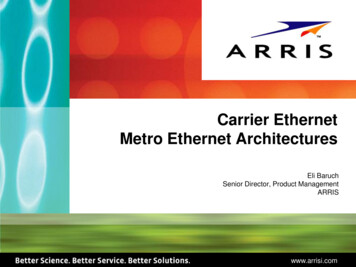
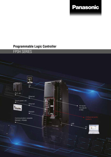
Chapter 1Secure Communication ArchitectureFigure 1 - 1756-EN2TSC module Establishes Secure Tunnels with Peer Modules, Windows 7 Clients,and VPN AppliancesEnterprise ZoneLevels 4 and 5Demilitarized Zone (DMZ)Secure Tunnel Between 1756-EN2TSCModule and VPN ApplianceDemilitarized Zone (DMZ)Manufacturing ZoneSite ManufacturingOperations and ControlLevel 3Secure Tunnel Between 1756-EN2TSCModule and Windows 7 Client.Level 0 2Peer-to-peer Secure TunnelBetween 1756-EN2TSC ModulesIMPORTANTControlLogix Chassis with1756-EN2TSC ModuleHMIs are not supported by the 1756-EN2TSC/B.HMIs don’t support IPsec.The 1756-EN2TSC module provides a level of protection against unauthorizednetwork access, either malicious or accidental, to a ControlLogix controller viaan EtherNet/IP connection. The 1756-EN2TSC module uses the InternetProtocol Security (IPsec) protocol suite to provide a secure communicationtunnel.The 1756-EN2TSC module is intended for use behind an existingfirewall/DMZ that help protect the plant network from outside access. Thismodule is not intended to be connected directly to the public Internet or toprovide a mechanism by which remote access is provided to a network. Themodule does not provide the ability to expose a private network address range viaIPsec; only the module’s IP address is available.10Rockwell Automation Publication ENET-UM003C-EN-P - November 2015
Secure Communication ArchitectureChapter 1ConsiderationsOut-of-the-box, the module functions just like a 1756-EN2T module, exceptthat the module does not support the following: Integrated motion on EtherNet/IP networks ControlLogix redundancy systems SIL 2 applications Email capabilities EtherNet/IP socket interfaceOnce security is enabled, modules like POINT I/O adapters, FLEX I/Oadapters, and PowerFlex drives are not able to establish a secure connectionbecause they do not support secure tunnels.When security is enabled, the module connects with: Upper level systems and user workstations with Windows 7 operatingsystems Stratix 5900 Services Router Cisco ASA security appliances Other 1756-EN2TSC modulesThe module supports the current versions of common web browsers, such asInternet Explorer (8 and 9). For security reasons, Secure Sockets Layer (SSL) 2.0and 3.0 are disabled in the module. Browsers must enable support for TransportLayer Security (TLS) 1.2.The 1756-EN2TSC module lets only those devices with proper credentialsaccess the module. This module is intended for use behind an existingfirewall/DMZ that help protects the plant network from outside access.To minimize complexity, the module supports the following authentication andencryption methods. IPsec technology with as many as eight VPN tunnels (only one of whichcan be a VPN appliance. Mobile Client Pre-shared key authentication AES encryption (128 bit, 192 bit, and 256 bit)Rockwell Automation Publication ENET-UM003C-EN-P - November 201511
Chapter 1Secure Communication ArchitectureLocal Chassis SecurityYou can use the 1756-EN2TSC module with the following features to preventunauthorized access to a controller in the local chassis. The trusted slot feature (in the controller properties) designates slots inthe local chassis as trusted. When the trusted slot feature is enabled, thecontroller denies communication through paths that are not trusted. Thisrequires authentication to the module for anyone to access the controllerwith programming software. The serial number lock feature (in the 1756-EN2TSC module properties)with the trusted slot features restricts communication through a module inthe trusted slot with the specific serial number.12Rockwell Automation Publication ENET-UM003C-EN-P - November 2015
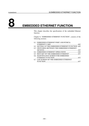
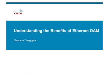
Secure Communication ArchitectureChapter 1The trusted slot and serial number lock features are for applications that haveconcern with physical access to and tampering with the controller.IMPORTANTNetwork Access SecurityUse caution with these features and make sure you have the controller projectbacked up in a secure location. If the module becomes disabled for any reason,you have to download to the controller to recover.The 1756-EN2TSC module uses the Internet Protocol Security (IPsec)technology to provide secure communication over the Ethernet network. IPsec iswidely deployed, and is often used to create Virtual Private Networks (VPN).IPsec provides the following security features: Authentication of the communication end points (both client and server) Data authenticity and integrity (via message integrity checks) Data confidentiality (via encryption algorithms)Use of the IPsec protocol suite lets you use the Microsoft Windows VPN clientto connect securely to the module. IPsec also lets the module create securetunnels with other 1756-EN2TSC modules and with off-the-shelf, VPNappliances.IMPORTANTThe module does not provide access to a private network.While the module supports secure communication, the module is not intendedto be connected directly to the public Internet and provide a VPN function, or bethe mechanism by which remote access is provided to a network. The moduledoes not provide the ability to expose a private network address range viaIPsec—only the module’s IP address is available.The module does the following: Secures access to the controller and I/O modules in the local chassis Secures bridge access to other networks accessible within the local chassisSecure Plant Network Access via1756-EN2TSCLogix5575RUN FORCE SDEtherNet/IP EtherNet/IP OKControlLogixChassisDeviceNet Access Via 1756-DNBEtherNet/IP Access Via 1756-EN2TRockwell Automation Publication ENET-UM003C-EN-P - November 201513
Chapter 1Secure Communication ArchitectureAs part of establishing the secure tunnel, both endpoints must authenticate witheach other and exchange information to help ensure secure data transfer.IPsec AssociationOnce the IPsec association is established, data between the two endpoints is fullyencrypted (except for produced/consumed tags) or optionally sent unencrypted,but with a cryptographic message integrity code.Table 1 - IPsec Capability DescriptionsCapabilityDescriptionAuthentication MethodPre-shared key (PSK). Configure a secret key on each of the endpoints.Header FormatEncapsulating Security Payload (ESP)Encapsulation ModeTunnel mode, defaultTransport mode used with Microsoft Windows 7 clientInternet Key Exchange IKE version 1 IKE version 2Negotiation Mode Passive ActiveLifetime(s)IKE and IPsec lifetimes user-configurablePFS GroupNoneDH Key GroupMODP groups 2 (1024-bit, default) 5 (1536-bit) 14 (2048-bit)IKE Encryption Algorithm AES(128 bit) AES(192 bit) AES(256 bit)IKE Authentication AlgorithmSHA-1IPsec Encryption Algorithm IPsec Authentication AlgorithmSHA-1AES(128 bit)AES(192 bit)AES(256 bit)NoneAs long as the IPsec traffic is received, the connection is considered alive. YourVPN connection can recover without having to reauthenticate if you lose yourconnection for a short time (few seconds). However, if the time since the lastreceived packet is greater than the timeout interval, the connection times out.This interval is common to all IPsec connections and is not configurable. Thedefault keepalive-timeout is 30 seconds.14Rockwell Automation Publication ENET-UM003C-EN-P - November 2015
Secure Communication ArchitecturePerformanceChapter 1The communication capability of the module is the same as the 1756-EN2Tmodule. The 1756-EN2TSC supports the following: The same number of TCP and CIP connections as the 1756-EN2Tmodule (256 CIP connections and 128 TCP/IP connections) The configuration of IPsec associations with as many as eight IP addresses(devices); only one of which can be a VPN appliance connection Mobile clients CIP Sync communicationTraffic FilteringWhen IPsec is enabled, the module blocks traffic that is not received via a VPNclient, another peer with an IPsec connection, or an appliance with an IPsecconnection, with these exceptions: BOOTP/DHCP traffic (to let the module obtain an IP address) HTTPS traffic (configure the module) CIP Sync packets (disable CIP Sync option) Logix produced/consumed tags (the establishment of theproduced/consumed connection occurs over via IPsec) 1756 I/O connections in a remote chassisIf the 1756-EN2TSC module is the trusted slot for a ControlLogix chassis, thefollowing traffic to the controller must go through the 1756-EN2TSC module. RSLinx Classic traffic (such as Studio 5000 and ControlFLASH communication) RSLinx Enterprise traffic (such as FactoryTalk View SE and FactoryTalk View ME communication)Rockwell Automation Publication ENET-UM003C-EN-P - November 201515
Chapter 1Secure Communication ArchitectureSecurity ConfigurationYou can enable and disable features of the module to enhance security. The USB port can be disabled. The remote factory reset via a CIP message can be disabled. The remote reset via a CIP message can be disabled. When you disable theremote reset, the ControlFlash update is also disabled.Table 2 describes the IKE and IPsec SA parameters that you can configure. Themodule profile dictates whether some parameters are configurable or not. Thereare also other parameters that you cannot configure (some of them are displayed,for example hash algorithm).Table 2 - IKE and IPsec SA Parameter DescriptionsParameterDescriptionGeneralSA IdentifierIPsec security association name.ProfileProfiles have values that are preconfigured for a specific type of connection.The generic client profile offers full customization. Peer-to-peer (two 1756-EN2TSC modules) Windows Client VPN Appliance (CISCO ASA 5500 series, Stratix 5900 )Negotiation modeIf active, the module tries to initiate connection. If passive, the module waitsfor the other side to initiate connection. Passive for Windows and Mobile client Active for peer-to-peer and VPN Appliance Active or passive for Generic Client (user-selectable)Exchange versionPhase 1 (IKE) exchange version. We recommend IKEv2. IKEv1 Main mode for Windows and Mobile client IKEv2 for peer-to-peer IKEv1 Main mode, IKEv1 Aggressive mode, or IKEv2 for Generic Client andVPN Appliance (user-selectable). IKEv1 Aggressive mode is faster but lesssecure than Main mode.Phase 1 (IKE negotiation)Local device identifier(Except Windows and Mobile client)16Identifier of this device. It must match other side remote identifier. IP address FQDN (fully qualified domain name) User FQDN (in form user@domain)Rockwell Automation Publication ENET-UM003C-EN-P - November 2015
Secure Communication ArchitectureChapter 1Table 2 - IKE and IPsec SA Parameter Descriptions (continued)ParameterDescriptionRemote device identifier(Except Windows and Mobile client)Identifier of remote device. It must match other side local identifier. IP address FQDN (fully qualified domain name) User FQDN (in form user@domain)Remote device IP addressIP address of other side of IKE/IPsec connection.Remote network IP(Only for VPN appliance)Base address of subnet reachable through VPN appliance tunnel.Remote network netmask(Only for VPN appliance)Netmask of subnet reachable through VPN appliance tunnel.Encryption algorithmEncryption algorithm for IKE exchange. AES 256 for Windows and Mobile client AES 128, 192, 256 otherwise (user-selectable)Pre-shared keyPSK text. Must match other side PSK.DH groupsMODP Groups 2, 5 and 14 are supported. Higher number of group offersincreased security, but requires more time and resources to establishconnection. At least 2 - accepts 2, 5 and 14, initiates connection with 2. At least 5 - accepts 5 and 14, initiates connection with 5. At least 14 - accepts only 14, initiates with 14.Key life time limitAfter this time, Phase 1 (IKE) keys are renegotiated. 8 hours by default for Windows and Mobile Client 24 hours by default otherwise 10 minutes minimumWe recommended that you use the default values.Phase 2 (IPsec negotiation)Encryption algorithmEncryption algorithm for data inside IPsec tunnel. NULL or AES 128 for Windows and Mobile client NULL, AES 128, 192, 256 otherwise (user-selectable)Key life time limitAfter this time, Phase 2 (IPsec) keys are renegotiated. 8 hours by default for VPN appliance 1 hour by default otherwise 10 minutes minimumWe recommended that you use the default values.Key life data limitWhen this amount of data has been transferred inside IPsec tunnel, Phase 2(IPsec) keys are renegotiated. Disabled (0) by default for Windows and Mobile Client 100000 KiB by default for peer-to-peer and Generic Client 4608000 KiB by default for VPN applianceWe recommended that you use the default values.Rockwell Automation Publication ENET-UM003C-EN-P - November 201517
Chapter 1Secure Communication ArchitectureNotes:18Rockwell Automation Publication ENET-UM003C-EN-P - November 2015
Chapter2Get StartedTopicPageInitial Powerup20Configuration Overview22Assign Network Settings23Configuration Overview22Create User Accounts25Generate HTTPS Certificate26Backup / Restore28This chapter describes the initial configuration settings that are required for themodule. After installing the module, see the next chapters for securityconfiguration examples.For information on how to install the module, see EtherNet/IP NetworkModules Installation Instructions, publication ENET-IN002.Add the module to a controller project the same as you add a 1756-EN2Tmodule. All security-related configuration is via the module web pages.IMPORTANTWhen you finish using the web pages, make sure to use the logout link in theupper right corner of the web page. Close all browsers to prevent others frompotentially accessing the web pages.Rockwell Automation Publication ENET-UM003C-EN-P - November 201519
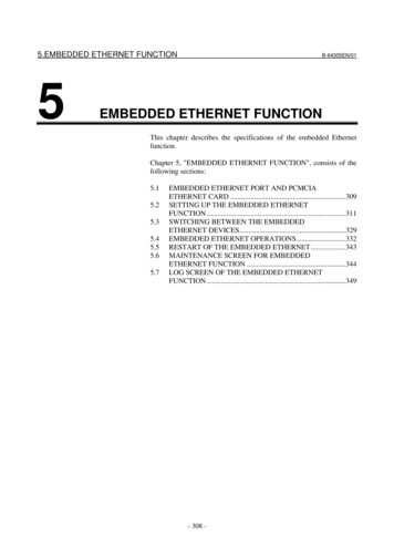
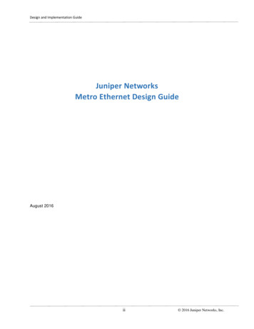
Chapter 2Get StartedConfigure all security parameters via the web server. In the Address field of yourweb browser, enter the IP address that displays on the front of the module.Specify the IP address of the web servermodule in the Address window of yourweb browser.After you login, the Home page appears.The 1756-EN2TSC module has an embedded HTTPS server that it uses toprovide secure web communication. An HTTPS server uses a certificate so thatthe client can verify server authenticity. For websites connected to the Internet,certificates are normally signed by a trusted certificate authority. Web browsersare then able to verify the authenticity of the web server by virtue of its certificate.The module uses a self-signed certificate. The module uses this certificate becausethe IP address is not known (at manufacture time) and cannot be signed bycertificate authority (CA). Self-signed certificates are not signed by a known,trusted authority, so they must explicitly be accepted by you (the user) whenconnecting via the web browser.Initial PowerupOn initial powerup, the module generates a new certificate for the embeddedHTTPS server. The certificate generation process can take up to a minute.During this process, the message ‘SSL certificate generation in progress’ is shownon the module display. Wait until the module is fully booted and ‘OK’ is shownon the display before accessing the module by using a web browser.1. In the Address field of your web browser, enter the IP address that displayson the front of the module.IMPORTANTWhen you enter the IP address, you must enter the prefix https:// in theaddress. If you enter an http:// prefix, the module redirects to thehttps:// prefix.After the web browser connects to the server, a warning message is shownabout the certificate that is not signed by a trusted authority.20Rockwell Automation Publication ENET-UM003C-EN-P - November 2015
Get StartedChapter 22. Accept this message and continue to the web page.IMPORTANTIn general, do not accept the certificate not being signed by a trusted authority.But in the case of initial powerup, the module has a self-signed certificate, socontinue to the website even though the message says that this option is notrecommended.The self-signed certificate warning continues to display unless you add thecertificate to the list of exceptions for the web browser.3. After accepting the self-signed certificate, enter the user ID and password.Rockwell Automation Publication ENET-UM003C-EN-P - November 201521
Chapter 2Get StartedDefault CredentialsDefault credentials are case-sensitive and are as follows: User name: Administrator Password: adminYou are prompted to change the password on the Administrator account. Enterthe new password and click Change.After you change Administrator password, the module home page appears.Configuration OverviewThe left pane of the web browser is a navigation tree to configure and maintainthe module.Only members of the Administratorsgroup can see all features.See the next chapters in this manual for different security configurations.22Rockwell Automation Publication ENET-UM003C-EN-P - November 2015
Get StartedAssign Network SettingsChapter 2By default, the module is BOOTP enabled.IMPORTANTDo not simply configure the initial address that is assigned to the module asa static IP address. Contact your network administrator for an appropriatestatic IP address.To assign an IP address, choose one of the following methods. Rotary switches on the module (before you install the module) Rockwell Automation BOOTP/DHCP utility (available with RSLinx and Studio 5000 environments) RSLinx software Studio 5000 environmentsFor information on how to assign network parameters, see EtherNet/IP NetworkConfiguration User Manual, publication ENET-UM001.Change Network Settings Via the Module Web PageChoose Administrative Settings Device Configuration NetworkConfiguration. An authenticated user can modify network parameters.Rockwell Automation Publication ENET-UM003C-EN-P - November 201523
Chapter 2Get StartedTable 3 - Network Configuration Parameter Descriptions24ParameterDescriptionEthernet Interface ConfigurationThe network configuration scheme: Dynamic BOOTP (default) Dynamic DHCP StaticIP addressIP address for the module:If you want to specify a static IP address for the module, you must also choose Staticfor the Ethernet Interface Configuration field.Subnet MaskSubnet mask for the module.Default GatewayGateway address for the module.Primary Server NameSecondary Server NameDNS server addresses, if you are using DNS addressing within your Logix program.Domain NameDomain name for the web server module, if you are using DNS addressing withinyour Logix program.Host NameHost name for the module.Name Resolution (DNS)Whether the module uses DNS addressing within your Logix program.Autonegotiate StatusHow to determine port speed and duplex: Autonegotiate speed and duplex (recommended) Force speed and duplexSelect Port SpeedPort speed (10 Mbps or 100 Mbps), if you chose to force speed and duplex.Select Duplex ModeDuplex (full or half), if you chose to force speed and duplex.Rockwell Automation Publication ENET-UM003C-EN-P - November 2015
Get StartedCreate User AccountsChapter 2You can define user accounts for the web interface to the module. Every user isauthenticated by a user name and a password. These accounts are typically foradministrators or others who need access to diagnostic information. Assign user accounts with access levels to manage who has access to changeconfiguration or to view module information. Define each user as a member of the Users group or the Administratorsgroup. Members of the Administrators group have all
Secure Communication Architecture Chapter 1 Considerations Out-of-the-box, the module functions just like a 1756-EN2T module, except that the module does not support the following: Integrated motion on EtherNet/IP networks ControlLogix redundancy systems SIL 2 applications Email capabilities EtherNet/IP socket interface