Transcription
SENSORLESS CONTROL OF STEPPER MOTORUSING KALMAN FILTERCHIRAYU SHAHBachelor of Engineering in Instrument & Control EngineeringDharamsinh Desai Institute of Technology, IndiaMay, 2000Submitted in partial fulfillment of requirements for the degreeMASTER OF SCIENCE IN ELECTRICAL ENGINEERINGat theCLEVELAND STATE UNIVERSITYDecember, 2004
This thesis has been approvedfor the Department of Electrical and Computer Engineeringand the College of Graduates Studies byThesis Committee Chairperson, Dr. Dan SimonDepartment/DateThesis Committee Member, Dr. Zhiqiang GaoDepartment/DateThesis Committee Member, Dr. Sridhar UngaralaDepartment/Date
ToMyself: Chirayu ShahMy Parents: Ashwin R. Shah & Varsha A. ShahMy Girlfriend: Hiral PatelMy Brother: Rikin Shah
ACKNOWLEDGEMENTI would like to express my sincere indebtness and gratitude to my thesis advisorDr. Dan Simon, for the ingenious commitment, encouragement and highly valuableadvice he provided me over the entire course of this thesis. His rigorous attitudes to dothe research and inspire thinking to solve problems are invaluable for my professionalcareer.I would also like to thank my committee members Dr. Zhiqiang Gao and Dr.Sridhar Ungarala for their support and advice.I wish thank my lab mates at the Embedded Control Systems Research Laboratoryfor their encouragement and intellectual input during the entire course of this thesiswithout which this work wouldn’t have been possible.My thanks also go to my mother and father, who is not even in USA butencourages me all the time on the phone. Also thanks to my brother, Rikin, androommates who support me during my hard time.Last but not least, I would like to thank my girlfriend, Hiral, for her consistentlove, support, understanding, encouragement, and for the life we experience together,both in our good times and hard times.
ABSTRACTDespite model improvements and different control algorithms, much work remains to bedone to attain maximum motor performance. This work attempts to achieve control andvelocity tracking for a step motor using optimization techniques. The resulting systemdisplays practical stabilization for velocity tracking of a voltage-fed permanent-magnetstepper motor. The control design is an output-feedback design that utilizes stator currentand rotor position measurements. The goal of this work is to design a controller that isrobust to load torques, cogging forces, and other disturbances satisfying certain boundsby estimating the speed and position of the motor using an extended Kalman filter. Thecontroller and the estimator are implemented in a Microchip PIC16F877 microcontrollerusing embedded technology, and speed control is achieved using the estimated motorstate. The PIC16F877 is interfaced to a PC through USART communication to send thereal time data to the PC for analysis and comparison with Matlab results.v
TABLE OF CONTENTSLIST OF FIGURES . ixLIST OF TABLES . xiiCHAPTER I -- INTRODUCTION. 11.1 SENSORLESS CONTROL . 21.2 LITERATURE SURVEY . 31.3 INTRODUCTION TO TECHNOLOGY . 51.4 THESIS ORGANIZATION . 6CHAPTER II – PROBLEM FORMULATION. 8CHAPTER III -- STEPPER MOTORS . 113.1 INTRODUCTION. 113.2 THEORY OF OPERATIONOF STEPPER MOTORS. 133.3 TYPES OF STEPPER MOTORS . 173.3.1 Permanent Magnet Stepper Motors . 173.3.2 Variable Reluctance Stepper Motors . 183.3.3Hybrid Stepper Motors . 203.4 COMPARISON BETWEEN VR AND PM STEPPER MOTORS . 213.5 STEPPER MOTOR SWITCHING SEQUENCE . 223.6 MODELING OF PERMANENT MAGNET STEPPER MOTORS . 273.7 SELECTION CRITERIA FOR STEPPER MOTORS . 313.7.1 Calculating Torque. 31vi
3.7.2Calculating Load . 323.7.3Frictional And Rotational Acceleration Considerations. 323.8 STEPPER MOTOR APPLICATIONS . 32CHAPTER IV-- KALMAN FILTER TECHNIQUE . 344.1 INTRODUCTION. 344.2 OBSERVERS . 354.3 KALMAN FILTER . 364.3.1 Introduction . 364.3.2 Discrete time Kalman Filter . 374.3.3 Filter Tuning. 424.3.4 Discrete time Extended Kalman Filter . 424.4 MOTOR MODEL FOR DISCRETE TIME EXTENDED KALMAN FILTER . 47CHAPTER V – HARDWARE AND SOFTWARE IMPLEMENTATION . 515.1 INTRODUCTION. 515.2 HARDWARE OVERVIEW . 525.2.1 The Stepper Motor . 525.2.2 Motor Driver Chip (L6208) . 545.2.2.1 Introduction. 545.2.2.2 Features . 565.2.2.3 Pin Description . 565.2.2.4 Motor Driving Phase Sequence . 585.2.2.5 Micro-Stepping Mode implementation Using L6208. 605.2.3 The Microcontroller (PIC16F877) . 64vii
5.2.3.1 Introduction . 645.2.3.2 Pin Diagram and Key Features . 665.2.4 Serial Communication Chip (MAX-202) . 675.3 HARDWARE LOOP . 695.4 SOFTWARE OVERVIEW . 74CHAPTER VI – RESULTS . 776.1 INTRODUCTION. 776.2 SIMULATION RESULTS . 776.3 EXPERIMENTAL RESULTS . 97CHAPTER VII CONCLUSION AND FUTURE WORK .1017.1 CONCLUSION. 1017.2 FUTURE WORK . 103BIBILIOGRAPHY . 104APPENDIXA MATLAB CODE . 109B PIC CODE (C PROGRAM). 119viii
LIST OF FIGURESFIGURE . PAGE3.1 Stepper Motor System. 113.2 Component of PM Stepper Motor (a) Rotor (b) Stator. 133.3 Six Pole Rotor and Four Pole Stator in Stepper Motor. 143.4 One Quarter Revolution of a Two-Phase Six Pole Stepper Motor . 163.5 Cutaway Diagram of a Permanent Magnet Stepper Motor. 173.6 Cross Section of VR Stepper Motor . 193.7 Hybrid Stepper Motor . 203.8 Current Rise Rate and Torque vs. Speed Relationship in Stator Winding . 223.9 Switching Circuit and Sequence Table for Full Step Mode . 233.10 Switching Circuit and Sequence Table for Half Step Mode. 253.11 Phase Current Diagram in Micro-step Mode . 263.12 Single pole, 2 phases - PMS . 284.1 On-going Discrete Kalman Filter Cycle . 394.2 Standard Kalman Filter Algorithm . 414.3 Extended Kalman Filter Algorithm . 465.1 Experimental Setup. 535.2 L6208 Functional Block Diagram. . 555.3 Pin Connection of L6208 . 565.4 Complete Circuit Diagram of L6208 . 595.5 Alignment of Micro-Stepping. 615.6 Microcontroller to L6208 Connection Diagram . 62ix
5.7 Pin Connection of PIC16F877 . 665.8 PIC to PC connection through MAX-202. 685.9 Circuit Diagram for MAX-202 . 685.10 PIC16F877 to MAX-202 Circuit Diagram . 695.11 PIC16F877 to Op-Amp Circuit Diagram. 705.12 PIC16F877 to L6208 Circuit Diagram . 715.13 Complete Circuit Diagram. 725.14 Complete Picture of the Hardware. 735.15 Flowchart of Software. 766.1 Position and Velocity for Open Loop Configuration. 786.2 Winding Currents for Open Loop Configuration. 786.3 Velocity and Position Response for Proportional Controller . 796.4 Winding Currents for Proportional Controller. 806.5 Position and Velocity Response with 5% White Noise Using PD Control . 816.6 Winding Currents with 5% White Noise Using PD Control . 816.7 True and Estimated (Position) Response Using KF . 836.8 True and Estimated (Velocity) Response Using KF. 836.9 Winding Current A and B Error (True minus Estimate) Response Using KF. 846.10 True and Estimated (Position) Response Using EKF . 856.11True and Estimated (Velocity) Response Using EKF . 856.12 Winding Currents A and B Error (True minus Estimate) Response Using EKF. 866.13 True and Estimated (Position and Velocity) Response Using DEKF. 876.14 Position and Velocity Error (True minus Estimate) Response Using DEKF . 87x
6.15 Winding Current A and B Error (True minus Estimate) Response Using DEKF . 886.16 True and Estimate (Position and Velocity) Response Using DEKF with PDControl . 896.17 Position and Velocity Error (True minus Estimate) Response Using DEKF withPDControl . 896.18 Winding Current A and B Error (True minus Estimate) Response Using DEKFwith PD Control . 906.19 Position and Velocity Response Using DEKF for Actual Measurement . 926.20 Position and Velocity Error (True minus Estimate) Response Using DEKF forActual Measurement . 936.21 Winding Current A and B Error (True minus Estimate) Response Using DEKFfor Actual Measurement . 936.22 Position and Velocity Response Using PD control with DEKF for ActualMeasurement. 946.23 Position and Velocity Error (True minus Estimate) Response using DEKF withPD Control for Actual Measurement . 956.24 Winding Current A and B Error (True minus Estimate) Response Using DEKFwith PD control for Actual Measurement. 956.25 Test Input Sine and Cosine from PIC16F877 . 976.26 Measured Winding Current across Sense Resistor . 98xi
LIST OF TABLESTABLE . PAGEI. Motor Simulation Specification .10II. PIN Description of L6208 57III. Resistor and Capacitor used with L6208 58IV. Key Features of PIC16F877 67V. Standard Deviation of Estimation Error of KF 82VI. Comparison Table of Error Norm Using Different Filters.90VII. Comparison Table of Error Norm Using Different Filters for ActualMeasurement from Hardware .96xii
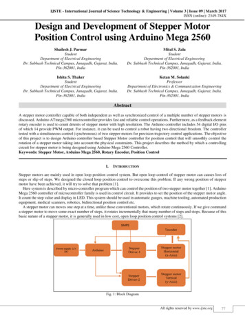
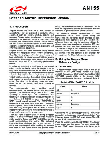
CHAPTER VIRESULTS6.1 IntroductionIn this work a sensorless technique for controlling the stepper motor using a Kalman filterhas been developed. Such a controller doesn’t need a sensor or encoder to measure thespeed or position of the motor; it estimates the speed and position using the measuredstates in form of either current or voltage. Here it estimates the speed and position fromthe measured states and uses that value for control by comparing it against the referencevalue. We can use P, PD or PID control, and we can tune the parameter values to getbetter control after getting the estimated states.In this chapter we simulate the system by using the proper system model and input inMATLAB, and then we implement the control algorithm in actual hardware to getexperimental test results.6.2 Simulation ResultsA number of simulations were carried out to verify the performance of the stateestimation, particularly of the speed estimation with EKF. First of all we run the systemopen-loop without any controller and check the steady state of the system as shown inFigs. 6.1 and 6.2. For open loop we run the system by applying the test input in the form77
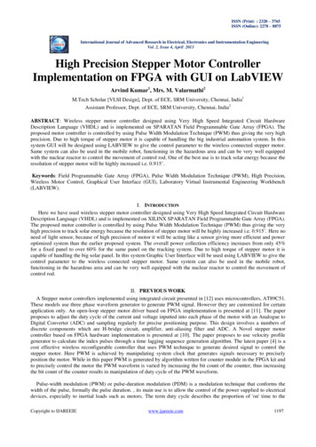
78of sine and cosine of 100 Hz frequency with given motor parameters. From Fig 6.1 wecan see that it stabilizes at 6.28 rad/sec value of speed. The current waveform of thewindings also looks smooth.8PositionVelocityPosition(radians) And .250.30.35Winding Current A (Amps)and Winding Current B(Amps)Fig. 6.1 Position and Velocity for Open Loop Configuration0.25Winding Current AWinding Current ime(sec)0.250.3Fig. 6.2 Winding Currents for Open Loop Configuration0.35
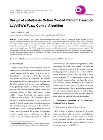
79Then we simulate the system with a proportional controller where the frequency of thesine and cosine is the control variable of the system. Fig. 6.3 shows the position andvelocity response of the system where the reference speed is 4 rad/sec. Fig. 6.4 shows thevelocity error response with time and Fig. 6.5 shows the winding current response.16Position(radians) And .52time(sec)2.533.5Fig. 6.3 Velocity and Position Response for Proportional Controller
Winding Current A (Amps)and Winding Current B(Amps)80Winding Current AWinding Current time(sec)0.160.180.2Fig. 6.4 Winding Currents for Proportional ControllerThen we simulate the system with PD Controller introducing 5% white noise (onestandard deviation) in the measurement of speed as shown in Fig. 6.6 6.8. Here, Isimulate the system for longer time until it gets steady state. We can see that at about 3sec the velocity response getting steady state condition.
8116Position(radians) And .52time(sec)2.533.5Winding Current A (Amps)and Winding Current B(Amps)Fig. 6.5 Position and Velocity Response with 5% White Noise Using PD ControlWinding Current AWinding Current time(sec)0.160.18Fig. 6.6 Winding Currents with 5% White Noise Using PD Control0.2
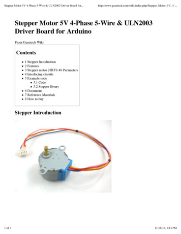
82Then we simulate the system with a continuous time Kalman filter. Here we used thefollowing noise parameters for the simulations.Control Noise 0.001 volts (Std dev of uncertainty in control inputs)AccelNoise 0.05 rad/sec 2 (Std dev of shaft acceleration noise)Meas. Noise 0.1 amps (Standard deviation of measurement noise)The standard deviation of the estimation error is shown below.EstimationErrorPosition(radians) Velocity(rad/sec) dingCurrentB(amps)0.0026641TABLE V Standard Deviation of Estimation Error for continuous time KFFig. 6.7 shows the true and estimated position response. We can see from the table andsimulation that the standard deviation of error is 0.00035. Figure 6.8 shows the true andestimated velocity response. Here, we can see that the estimated velocity is fairly close tothe actual velocity. Fig 6.9 shows winding currents error (actual minus estimated) forboth currents. We can see from the figure that error is very small in both the cases.
.60.8time(sec)11.21.4Fig. 6.7 True and Estimated (Position) Response Using Continuous Time 60.8time(radians)11.21.4Fig. 6.8 True and Estimated (Velocity) Response Using Continuous Time KF
Winding Current A(Amps) and Winding Current B Error(Amps)840.06Winding Current A ErrorWinding Current B .20.40.60.8time(sec)11.21.4Fig 6.9. Winding Current A and B Error (True minus Estimated) Response UsingKFThen we simulate the system with the hybrid extended Kalman filter with the same noise.The simulation result is shown in Figs. 6.10 6.12. Fig 6.10 shows the true and estimatedresponse for position. We can see that estimated result is very close to the actual results.Fig 6.11 shows the true and estimated velocity response. We can observe that estimatedresponse is more close to the actual response compare to the Kalman filter. The standarddeviation of velocity error is 0.051. Fig 6.12 shows the winding currents error (actual –estimated) response for both windings. We can see from the response that error value isless compared to the Kalman filter.
ime(sec)0.30.350.40.45Fig. 6.10 True and Estimated (Position) Response Using Hybrid 45Fig. 6.11 True and Estimated (Velocity) Response Using Hybrid EKF
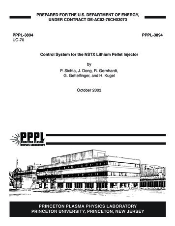
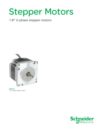
Winding Current A(Amps) and Winding Current B Error(Amps)860.06Winding Current A ErrorWinding Current B .050.10.150.20.25time(sec)0.30.350.40.45Fig. 6.12 Winding Current A and B Error (True minus Estimated) Response UsingHybrid EKFThen we simulate the system with the discrete time extended Kalman filter with asampling time of 0.001 sec. The simulation results are shown in Fig. 6.13 and Fig. 6.14.Fig. 6.13 shows the true and estimated velocity and position response using discrete timeextended Kalman filter. We can see from figures that estimated results are very closelyfollowing the actual results. Fig. 6.14 shows the error response of velocity and position.We can see from that the error value is really smaller and its magnitude is in power of10 (-5) , which is really small compared to the KF and EKF. Fig. 6.15 shows the errorPPresponse for winding current A and B. From the figures we can see that the error value ismuch smaller compared to the continuous time EKF and hybrid EKF.
0.150.20.25time(sec)0.30.350.4Fig. 6.13 True and Estimated (Position and Velocity) Response Using DEKF-5position Error(radians)x .350.40.45velocity Error(rad/sec)x Fig. 6.14 Position and Velocity Error (True minus Estimated) Response UsingDEKF
Winding Current A (Amps)and Winding Current B(Amps) Error88-4x 102.5Winding Current A ErrorWinding Current B me(sec)0.30.350.4Fig. 6.15 Winding Current A and B Error (True minus Estimated) Response UsingDEKFThen we simulate the system using PD control with the discrete time extended Kalmanfilter. Figure 6.16 shows the true and estimated position and velocity response usingdiscrete time extended Kalman filter with PD control for velocity loop. We can see fromfigures that velocity control loop is working really good with estimated result and veryclose to true results. Figure 6.17 shows error response for position and velocity betweentrue and estimated value. We can see from the figure that magnitude of error iscomparably smaller than KF and EKF. Figure 6.18 shows the winding currents errorresponse
.522.5time(sec)Fig. 6.16 True and Estimated (Position and Velocity) Response Using DEKF withPD Controlposition Error(radians)-52x 1010-1-200.511.522.51.522.5velocity 0.51time(sec)Fig. 6.17 Position and Velocity Error (True minus Estimated) Response UsingDEKF with PD Control
Winding Current A (Amps)and Winding Current B(Amps) Error90-4x 10²Winding Current A ErrorWinding Current B e(sec)0.30.35Fig. 6.18 Winding Current A and B Error (True minus Estimated) Response UsingDEKF with PD Control0.00035278Error norm ofError normVelocity (rad/sec) of WindingCurrent A(amps)0.135470.0020486Error normof WindingCurrent 060.00279870.000105870.00010662Error normof position(radians)ContinuousKalman FilterHybrid ExtendedKalman FilterDiscrete timeExtended KalmanFilterDiscrete timeExtended KalmanFilter With PDcontrolTABLE VI Comparison Table of Error Norm Using Different Filter
91The above table shows the comparison of the error norm between the true value andestimated value of stepper motor position, velocity and winding currents while applyingthe Kalman filter, hybrid extended Kalman filter and discrete time extended Kalman filterand discrete time extended Kalman filter with PD control. Here, we keep the controlnoise equal to 0.001, process noise 0.05 and measurement noise 0.1 for all thesimulations. From the results we can see that the error norm using the hybrid and discreteKalman filter is small compared to the continuous Kalman filter. This may be because theintegration step size for the continuous time Kalman filter was too large (recall that thecontinuous time Kalman filter assumes continuous dynamics and measurements). Thediscrete time extended Kalman filter and discrete time EKF with PD control haveapproximately the same error norm. So we can say that discrete time extended Kalmanfilter works well for this model and we can implement it in hardware using amicrocontroller.The above MATLAB results are simulated by assuming some standard test inputs andapproximating the noisy measurements by introducing some noise to the true simulatedwinding currents. But now we simulate the same system in MATLAB by using the actualsine and cosine that are input to the motor and using the current waveforms that wemeasured from the hardware-based system. Here we used the steady value of Kalmangain which we get by simulating the system until it reached steady state. Figure 6.19shows the velocity and position response using the discrete time extended Kalman filter.We can see that estimated value is closely following the true value. Figure 6.20 shows
92position and velocity error response using the DEKF. Figure 6.21 shows the windingcurrent A and B error response using the discrete time extended Kalman filter. Here wesimulated the whole system in the two parts that we are trying to achieve in real time. Werun the motor equation (time update) for 6 ms with a 0.2 ms sampling time. After that weupdate the estimation of the states (i.e., measurement update every 6 ms) using the steadystate value of Kalman gain, which we can later use to control the speed or position. Thesevalues were obtained on the basis of the microcontroller timing that was required for thetime update imated13121110900.050.10.150.20.25time(sec)Fig. 6.19 Position and Velocity Response of the DEKF Using Actual Measurements
93position Error(radians)-31.6x 101.41.2100.050.10.150.20.250.150.20.25velocity 1time(sec)Fig. 6.20 Position and Velocity Error (True minus Estimated) Response of theWinding Current A(Amps)and Winding Current B(Amps) ErrorDEKF Using Actual Measurements0.1Winding Current A ErrorWinding Current B 50.10.150.20.25time(sec)Fig. 6.21 Winding Current A and B Error (True minus Estimated) Response of theDEKF Using Actual Measurements
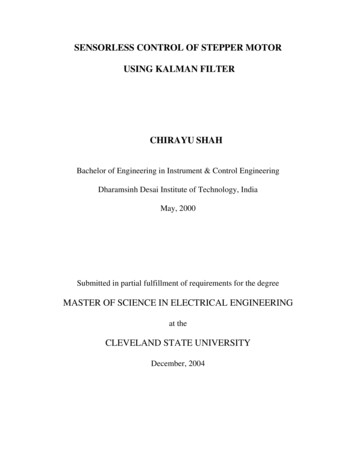
94We then simulated the same system using PD speed control. Figure 6.22 shows theposition velocity response using PD control where we use the EKF estimate of speed toobtain speed control of the motor. Figure 6.23 shows position and velocity error responsefor the discrete time extended Kalman filter with PD control. Figure 6.24 shows thewinding current A and B error (true minus estimated) response for the DEKF using PDcontrol. Here from the figures we can see that error value is large compared to thatobtained through simulated Estimated13121110900.050.10.150.20.25time(sec)Fig. 6.22 Position and Velocity Response Using PD Control of the DEKFUsing Actual Measurements
95position Error(radians)-415x 101050-500.050.10.150.20.250.150.20.25velocity 1time(sec)Fig. 6.23 Position and Velocity Error (True minus Estimated) Response of theWinding Current A (Amps)and Winding Current B(Amps) ErrorDEKF Using PD Control0.1Winding Current A ErrorWinding Current B 50.10.150.20.25time(sec)Fig. 6.24 Winding Current A and B Error (True minus Estimated) Response of theDEKF Using PD Control
96Error normof position(Radian)
stepper motor. The control design is an output-feedback design that utilizes stator current and rotor position measurements. The goal of this work is to design a controller that is robust to load torques, cogging forces, and other disturbances satisfying certain bounds . CHAPTER VI - RESULTS .