Transcription
IntroductionThe management and staff at CMH have been designing and building permanent mold casting machines since1959 and the resulting machine is one of the highest profit makers in the field today. We have combined ouryears of experience to bring you the following “Tilt Pour Permanent Mold Casting Guide.”CMH has continuously strived to improve its products and improve the productivity of our customers.Automated hydraulic, electronic and electric operations of all phases of the casting process, including castingremoval and ladeling, have dramatically increased production.The ProcessAluminum casting alloys are the most versatile of all common foundry alloys and generally have the highestcastibility ratings. Aluminum is adaptable to many of the commonly used casting methods and can be readilycast in metal molds mounted on CMH casting machines for high volume, cost-effective castings.In general, aluminum alloys have the following characteristics: Good fluidity – important for filling thin sections Low melting point – lower melting and casting temperatures relative to those required for many othermaterials Lower density – the lighter weight of aluminum allows for easier handling in the foundry, compared toferrous alloys Fast heat exchange – heat transfer from the molten aluminum to the mold is relatively fast, providingfaster castings cycles in metal molds Good chemical reproduction – chemical stability is relatively good Good as-cast surface finish – surfaces are lustrous and have few blemishesThe tilt pour process using CMH tilting devices involves the production of castings by pouring liquid aluminuminto permanent molds and tilting the mold, allowing a controlled flow of liquid aluminum to fill the mold cavityby gravity. Basically the process involves the following steps: A refractory mold wash is sprayed onto the surfaces of a preheated mold that will be in direct contactwith the molten metal alloy Cores, if applicable, are inserted, and the mold is closed by the ram cylinder The alloy, heated above its melting temperature, is poured into a pouring cup The tilting device tilts down allowing the liquid alloy to fill the mold cavity at a controlled rate After the alloy has been allowed to solidify, metal cores and other loose mold members are withdrawn,the mold is opened, and the casting is ejected (usually with the casting machine in the tilted up position) Steps two and four are repeated until repair of the mold coating is required, at which time step one isrepeated Usual foundry practices are followed for trimming gates and risersWhen permanent mold casting is combined with nonmetallic cores, such as sand cores, the process is referred toas semi permanent mold.Applications for Permanent Mold CastingsAluminum permanent mold castings are widely used throughout industry. As the United States governmentmandates more fuel-efficient cars, the demand for permanent mold castings has steadily increased. Suspensionlinks, intake manifolds, pistons, and other functional parts of internal-combustion engines are typicalapplications. Other applications include aviation engines, missiles, motor housings, portable tools, nozzles, fancases, outdoor lighting standards, gear cases, lawn mower chassis, barbeque grills, and kitchen pots and pans.
Advantages and DisadvantagesBecause of the various factors that must be considered when choosing a casting process the decision to usetilt pour permanent molding should be based on thorough engineering and production cost studies. Properlyengineered well- made tilt pour castings will have the following advantages: Dimensional accuracy is superior to sand or shell mold castings, because the mold is rigid and does notallow mold wall movement during solidification. Additionally, dimensional repeatability is improved.The reduction in casting variations allows a reduction in machining allowances, which will lower thedown stream cost. Ferrous and nonferrous inserts can be accurately cast in place. Typical insert materials can be iron, steel,stainless steel, or copper base alloys. In some cases, threaded inserts can be cast in place, eliminatingthe need for machining and related costs. Because permanent mold castings are chilled castings, they are generally sounder than sand castings.Permanent mold castings are generally stronger than sand or die-castings and are less porous than diecastings. Castings produced in the permanent mold process have finer dendritic arm spacing (DAS) andgrain structure. The finer structure displays better strength properties than those cast in similar alloysin sand castings. Permanent mold castings have fewer inclusion defects than sand castings. Therefore,the casting designer has the freedom to use thinner sections and lighter weight designs. Permanent moldcastings have a higher degree of reliability with regard to pressure applications of fluids and gases. The tilt pour process allows the molten metal to flow to the bottom of the mold, forcing the air out thetop. As the molten aluminum flows through the runner a static skin of aluminum oxide forms whichallows clean metal to enter the mold cavity. Automatic pour machines eliminate many of the variables found in hand pouring. Generally, permanent mold castings require less finishing than sand castings. Permanent moldcastings have a smoother as cast surface finish than sand casting and finishes approaching 100rms canbe achieved. In many cases casting buyers can use as cast surfaces without subsequent finishing forcooking utensils, hardware items, automotive parts, and ornamental work. Studs, nuts, bushings, pipes and other inserts may be cast as integral parts of the casting. The insertsmust be held in positive position in the mold to prevent movement during casting process. The insertsshould be scored, knurled, or under cut to provide a locking surface.There are limitations to the size of castings produced in the permanent mold process. Most castings weight lessthan twenty pounds, however castings as large as 350 pounds have been poured. The casting design may be socomplex that it is not practical in permanent mold processes.Mold DesignIn permanent mold casting, solidification occurs much more rapidly than in sand casting. However tilt pouringallows better filling of the mold with minimum turbulence and controlled thermal gradients to establishdirectional solidification towards a riser. The rigidity of a permanent mold necessitates some differences in theapplication of these principles. It is essential that the entire casting and its gating system be removed with asimple parting from the mold. Removal must be possible without excessive mechanical force on the casting or
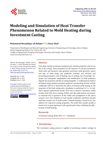
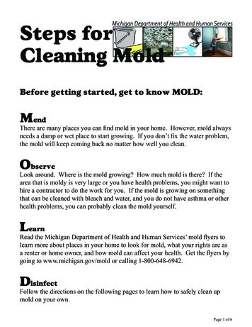
without excessive abrasion of the mold coating. A CMH front ejector will ensure that the casting draws straightand pulls with the movable mold half.Heavy sections are generally placed on the parting line to permit feeding. Sprues, runners, gates and risers arealso placed on the parting line so they can be stripped with the casting. The casting and gating system mustbe arranged to promote directional solidification starting in the remote areas and progressing towards the riser.Due to the wide variation in cross sectional area of commercial castings it may be necessary to use highlyconductive chills, air cool, water cool or take advantage of varying the mold wall thickness in order to promotedirectional solidification. Adequate gravity head should be provided to ensure filling of all parts of the cavity.Ample flat area should be allowed to seal against metal leakage atthe parting line. Two inches at the bottom and one and one halfinches at the sides is normally enough to seal molds up to thirtyinches square. Caution must be used when designing molds notto make them too rigid. The parting line is the hottest portionof a mold, and each face of the mold/platen assembly will runprogressively cooler (see fig. 1). Different heating of the mold willcause the mold to open at the parting line. In order to preventmold warping at the parting line, over all mold thickness should beheld to a minimum and stiffening ribs should not be used.Figure 1Mold design can dramatically affect casting quality as well. When designing a mold, the following factors mustbe considered. Venting Gating and risering ChillsVenting – All the air in the mold must escape as the mold is filling. Natural outlets, such as the parting line,and clearances around ejector pins, usually provide adequate venting. A properly designed gating system in thetilt pour process can reduce the venting necessity. The molten metal can be taken to the bottom of the mold,there by forcing the air out the top as the mold is tilted. In some cases, supplemental venting must be added.Commonly used venting methods include:1. Slot or “scratch” vents usually .005 to .010 inches deep, cut along the parting line leading to the outsideof the mold2. Very small holes drilled through the mold in areas where they will not affect the casting surface or theability to strip the casting3. Plug vents, which are holes that are drilled in the mold and filled with a slotted plugGating/risering – As the mold is tilted, molten aluminum enters the permanent mold and loses heat rapidlycompared to sand molds. The rapid cooling also necessitates rapid filling. In general, the gating/risering systemin the tilt pour process should accomplish the following: Fill the mold cavity in a tranquil manner reducing turbulence and the formation of dross Feed the casting during liquid contraction Provide fast solidification to increase production by reducing cycle time Promote progressive solidification to the riser Minimize further down stream processing (decrease finishing time for gate removal)
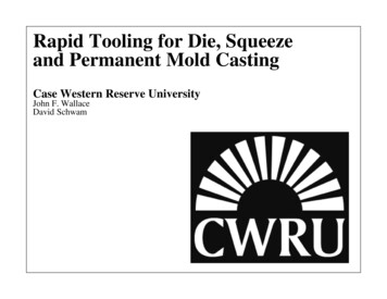
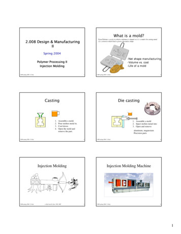
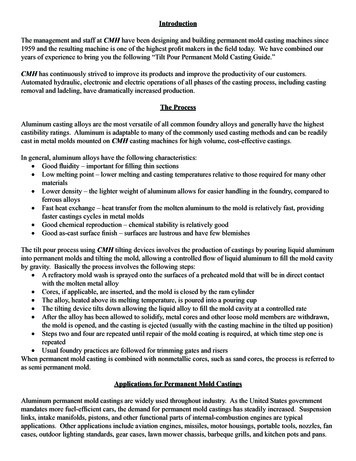
Figure two illustrates three types of tilt pourgating. The multi ingate system has lowerfinishing cost, but can cause turbulenceand dross defects. If high quality levels arerequired, the continuous ingate might bedesirable. This system could be used witha top riser and/or shrink bobs as necessary.Direct gating can be used very effectivelyin tilt pouring because the automatic tiltingof the mold eliminates human variabilityin the pour rate. Additionally, as the liquidaluminum enters the mold it flows through Figure 2a static skin of aluminum oxide. The oxideacts as a barrier allowing only clean metal to enter the mold cavity.The use of a side riser permits more control over distribution of the metal into the casting cavity through thegates. With castings of irregular cross section, it may be desirable to vary the rate of fill to sections of greateror less mass. The CMH programmable tilt option was designed to allow the caster to very the tilt rate, thereforethe mold fill rate, as necessary. In such cases multi ingates may be placed at various levels to allow metalto flow at the most desirable rate. For large castings, the gating system might be placed on both sides. Inapplications when a runner/riser is being used, a runner extension should be used to prevent the backwashing ofdross contaminated first metal of the pour.The actual dimensions of the mold and gatingsystem will depend on the weight and dimensionsof the casting to be produced. Figure four is givenas a guideline. All the dimensions are based on thethickness of the casting which is referred to as “T”. Inpermanent mold casting riser sizing is critical. Theriser must be large enough to eliminate shrinkagedefects. In some cases an over size riser van superheatthe mold and actually cause a shrinkage defect in thecasting. Furthermore, a riser in which metal freezestoo slowly may delay the opening of the mold untilexcessive contraction stresses have developed in theFigure 3casting. An oversize riser will increase cycle time and reduce productionChills – In absence of other variables, the thin sections(sections of low modulas) will naturally solidify before theheavy sections (sections of higher modulas). When the shapepermits, it is preferred to place the casting in the mold so thatsolidification starts in the thinner sections and progresses tothe heavier sections. Due to the wide variation in castings,this is not always possible and a hot spot will form. Somerelief may be obtained by adding ribs to a boss to introducemore feed metal into the heavy section. Ribbing is not alwayseffective or the casting may not be modifiable. In such cases,it is prudent to cool the heavy section of the mold so that the Figure 4casting will solidify quickly.
Localized chilling can be obtained by installing copper inserts (fig. 4). Extending them outside the mold andcutting cooling fins into the chill can increase their effects. Air chills are holes drilled into the mold and ablast of air is blown into to the relief. Moderate control of solidifications can be accomplished by varying thethickness of the mold coating.Mold MaterialsMold materials for permanent castings are usually chosen on the basis of the number of castings to be producedand the cost of mold materials plus machining. Regardless of the mold material selected, all materials mustinclude the following properties: The mold material must have adequate machinability. Machining the cavity is often the most significantcost factor. Tool wear, breakage, peed and feed rates all influence mold cost. Gray iron die blocks canusually be machined for less cost than tool steels. The mold must have good dimensional stability, high temperature strength, and thermal shock andfatigue resistance. The mold should not warp or change uncontrollably in size during the cycle. Themold must be able to withstand prolonged and repeated thermal cycling without softening, cracking oroxidizing. The mold material must be ear resistant to reduce dimensional changes caused by sand blasting, handcleaning, liquid metal erosion, abrasion from moving mold components and abrasion from castingremoval. Molds must display good thermal conductivity properties. Thermal conductivity is the rate heat flowsthrough a unit area of material under a given temperature gradient. Higher thermal conductivities reducecycle time and produces finer cast aluminum structure by cooling the casting faster.Good quality hot work tool steel is preferred for most medium to high production permanent mold applications.As noted above, the steel should have the following properties. Low thermal expansion coefficient High yield strength High temper resistance Good resistance to erosion High thermal conductivityThe thermal expansion coefficient should be low in order to maintain low thermal stresses. A high thermalconductivity reduces the thermal gradients and thereby the thermal stresses. High hot yield strength isbeneficial in resisting heat checking. Although the mold may begin with high hot yield strength, it may softenduring use due to constant exposure to heat from the casting metal. As the mold material softens, the risk ofheat checking damage increases. The softening associated with temper resistance is clearly accelerated bymechanical load. The mold is exposed to both high temperature and mechanical load.In permanent mold casting of aluminum, certain factors are critical to mold life and the need for moldmaintenance and repair. Some of the factors are: Heat checking Erosion Gross cracking Plastic deformationHeat checking is a thermo-mechanical fatigue process caused by thermal cycling, which creates cyclic stressesand strains in the cavity surface. Typical damage is the gradual growth of a network of fine cracks. Heatchecking is considered as the normal mold life-limiting factor. As noted above, high hot strength, as well as a
high tempering resistance are important mechanical properties of the mold material to obtain resistance to heatcracking. Additionally, toughness and ductility have shown to produce beneficial effects. Among physicalproperties of the mold material, low thermal expansion and high thermal conductivity are fundamental for heatcracking resistance.Erosion is a complex phenomenon, which includes both chemical and mechanical wear processes. It is a verycommon failure mechanism in permanent mold casting. It occurs first in the exposed parts of the mold, suchas gate areas, and special maintenance is required to prevent erosion. Besides good chemical resistance to themolten casting metal, high hot strength in the mold material is necessary for corrosion resistance.Gross Cracking is the catastrophic cracking of the die, due to mechanical or thermal overloading. Thisphenomenon can occur suddenly, completely destroying the mold. In practice, gross cracking is rare, butbecause of its abrupt and devastating consequences, it must be avoided.Plastic deformation, or indentations in the cavity, is a matter of insufficient hot strength in the mold in relationto actual mechanical strain. Hot strength and tempering resistance in the die material are of crucial importancein avoiding plastic deformation.The demands on the mold material used in permanent mold casting are heat and thermal fatigue cracks are themost common cause of mold failure. Thermal fatigue cracks are caused by a combination of thermal cyclicstress and plastic strain on the surface. The plastic strain starts the crack and tensile stresses propagate the crackgrowth. The following factors influence thermal fatigue: Preheating temperature Surface temperature Holding time at peak temperature Cooling rateThe preheating temperature should be a minimum of 300 F (150 C). At this temperature the fracture toughnessis almost twice as high as room temperature. At surface temperatures of 1100 F (600 C), the stresses aremoderate for normal tool steel, but at higher temperatures the risk of heat checking is significant. Longerholding time implies an increased risk of over tempering a mold. This will result in a reduction of themechanical strength and accordingly a lower resistance to mechanical and thermal loading. More rapid coolingresults in greater stresses and will lead to premature cracking.During casting the metal enters the mold as a liquid. Under certain conditions it can lead to a reaction betweenthe molten metal and the mold steel and can dissolve the steel. This phenomenon is known as erosion orcorrosion of the mold. Factors that influence erosion are: Temperature of the casting metal Composition of the casting metal Design of the mold Heat treatment of the mold Surface treatment of the moldCasting alloys have critical temperatures above which erosion attack increase. In most aluminum alloys,the critical temperature is 1330 F (720 C). Pure aluminum attacks the mold material at a greater rate thancommercial alloys. Gating and mold design is critical in preventing erosion. A thin directed jet of molten metalfrom a gate can cause hot spots and erosion problems. Care should be taken to avoid designs where jettinggates are near a core or cavity wall. If metallic contact between the mold and the molten metal can be avoided,the risk of mold erosion can be reduced. It is imperative that molds be properly coated with a refractory coatingat all times. Mold coating touch up must be performed during the workday to ensure that the risk of erosion is
minimized. In extreme cases molds can be nitrided to give extra protection.Other types of mold materials include: Cast iron Ceramics Graphite Tungsten (normally a core material) Beryllium copper (normally a chill material)
Mold CoatingPermanent mold coating is one of the operational parameters of the casting process that is often overlooked ormisunderstood. Permanent mold coatings are necessary for three basic reasons. Coatings provide a protective barrier between the mold and the casting to prevent mold erosion andwear. Coatings provide some degree of control over the solidification rate and direction. Coatings provide a barrier between the mold and the casting so that the casting will release from themold.With proper use, a permanent mold coating can be used to control the thermal gradients such that directionalsolidification can be achieved. This allows a pathway for feed metal to flow into the solidifying structure andcompensate for normal metal shrinkage during solidification. This is particularly important in castings with thinsections changing to think sections. The thin areas must remain open to ensure that shrinkage will not occur inthe adjacent thick section.In some casting designs there might be two or more characteristics working against one another. For example,a design might have a thin walled section in need of additional insulation to prolong solidification yet is alsoin an area that is difficult to release from the mold. In this case a compromise must be reached. By their verynature release coatings are not insulative and insulative coatings will not aid in the release of tight or difficultgeometries. In such cases a choice must be made as to which of the two operational characteristics is mostimportant. One choice may be to use a combination coating that will allow for some insulation and somerelease. Another option is to use an insulating coating as a base coat and a release top coat.Insulation coatings can vary greatly in insulating qualities as well as the surface finish the coating will impartto the casing. The insulating qualities of a coating are a function of the type of refractory filler that is used andtheir thermal conductivity and heat capacity. Also contributing to a coating’s insulative capabilities, as well assurface finish, is the amount of binder and the dilution rate. Typically binders are a sodium silicate. Typicalrefractory materials found in mold coatings include: Vermiculite Bentonite Talc Titanium dioxide Alumina Olivine GraphiteRelease and chill coatings both contain materials that act as heat conductors to allow for more rapidsolidification while protecting the mold against wear. Release coatings typically contain graphite as thelubricant, which is non-wetting by aluminum.
Mold Coating ApplicationAs in any coating application, surface preparation is critical. New molds should be thoroughly cleaned (seePreparation of a New Mold, next section). Molds that have been in service must have all the old coatingscompletely removed. The type of cleaning media used varies and includes sand, metal shot, grit, class beadsand dry ice (CO2). The choice depends on availability as well as how difficult the coating is to remove. In mostcases it is recommended the dry ice blasting be used for routine cleaning with periodic sand blasting to restorethe mold surface finish for mold coating. Over blasting, especially with sand, shot, or grit, can erode molddetail and shorten mold life.Mold coatings should be sprayed onto the mold surface with an airless spray gun or an aspiration type spaygun. Spraying equipment may be one of many different styles and types of spray guns. Use of a paint gun isnot recommended as the heavy materials in the mold coating easily clog the small ports. A siphon type gunthat has one straight fluid tube with replaceable fluid tips works well. Some siphon guns are available withinterchangeable pots. With extra pots, two or three different types of coating may be kept on hand, mixed andready. As the need arises for a particular coating, it may be snapped on the spray head and used immediately.In areas where a high degree of insulation is required, such as gates, runners, risers and pouring cups, brushingthe coating on will provide more insulating capability. In addition to the insulating properties of the coatingitself, brushing will trap air bubbles, which enhance insulation. Additionally, the rough surface caused bybrushing can aid in molten metal flow through the gating system by continuously disrupting the oxide skin asthe metal flows.Thoroughly mix the coating in its original container before diluting or using only a portion of the can weight.This will alleviate any settling problems that can occur during transit and storage. When diluting, soft warmwater works best, but cold water is acceptable. In either case, adequate mixing with any equipment such as aLighting miser or a bent rod in a hand drill is required. Excessive shear should be avoided.The mold should be heated to 600 F (315 C). Care must be taken to heat the mold uniformly. Opticalpyrometers should be used to determine if the mold is heating evenly. While the mold is hot it should besprayed lightly with water. This will increase a porous oxide film on the mold, which will provide a goodsurface for the mold coating to bond to. The water spray also cools the mold to the desired coating applicationtemperature, 350 - 400 F (75 - 200 C). If the molds are too hot, the rapid expanding water vapor frontmoving away from the mold will cause a phenomenon known as “kick back,” and very little coating will adhereto the mold. Even the coating that does adhere will not be properly bonded. If the mold is too cold the coatingmight run resulting in an uneven surface.Depending on the brand of coating, a primer coat may be required. This could be a specifically designed primeror a diluted version of the main coating. The purpose of the primer coat is to create the best possible adherenceof the coating to the mold. This occurs because very diluted sodium silicate solutions allow for bonds thatare more parallel to the mold face. This structure forms a stronger bond, which is more resistant to wear. Incontrast, high sodium silicate solutions create bonds that are perpendicular to the mold face and can be shearedoff. Care must be taken not to over dilute the primer coating, as sufficient sodium silicate must be present togenerate the bond. Once the primer is applied, the main coating can be applied at higher concentrations. Donot try to cover the mold face with one heavy coating. A gradual build up of the coating is preferred over oneheavy coat. The number of coats and the exact coating thickness will vary with the casting design and mayvary within the mold itself. A working profile should be developed for where a heavier or thinner application ofcoating should be applied to aid solidification. After the coating has cured, excess coating should be removedfrom the parting line and core prints with a wire brush or soft brass scraper.
As noted, most all commercial mold coating materials are bonded by sodium silicate with carious fillermaterials for their insulative, lubricative or cosmetic qualities. Mold coating is supplied in five-gallon cans orfifty-five gallon drums. The coatings should be stored in their original covered containers with the lids firmly inplace when not in use. Mold coating should be stored in a dry place away from excessive heat or cold or drastictemperature change. Ideal storage temperatures range from 50 -75 F (10 -25 C). Under no circumstancesshould the coating material be allowed to freeze, as subsequent thawing may not restore the coating to itsoriginal condition. Refer to the coating manufacturer’s instructions for additional storage information.Preparation of a New MoldA new mold should be first heated to approximately 600 F (345 C), with the ejector pins retracted, using agas burner and a gentle flame. The rate of heating should be very slow, taking about six hours for a 24 x 24mold. A magnetic thermometer, optical pyrometer, or a temple stick should be used to check the temperatureperiodically.Make sure all oil and other products of machining are burned off. The mold should be lightly sand blastedwith 100 mesh or finer silica or glass beads. Ejector pins should be extended after removing from the heat, butretracted before sandblasting.While the mold is still above 300 F (150 C), the primer spray may be started. If not, it may be necessary to reheat the mold with the burner. If re-heating soots the mold, additional sand blasting will be necessary.Proper original mold priming temperature is 300 -375 F (150 -190 C) for the original primer coat. Additionalcoats of spray may be put on at higher temperatures. If brushing is used to build up insulative coatings on gates,it should be done at 160 -220 F (70 -105 C). Gates that are brush painted should first be coated with primer.Touching up a mold while in use goes much the same as preparing a new mold, but some extra rules must beused. Make sure any sheared or stuck on aluminum is removed before adding the touch up coat. If coating areais spalled, cracked, or blistered, be sure to remove it with sand paper, steel wool, or steel brush.Specific Gravity to Control SolidificationIn aluminum permanent mold casting the solidification rates are typically faster than in sand casting, dueprimarily to the greater thermal conductivity of the metal mold as compared to the sand mold. This fastersolidification rate allows for a much finer and more densely compact grain structure. Because of the tightergrain structure, castings can be made with higher levels of dissolved hydrogen, since the faster solidificationrate will not allow the gas to come out of solution in such a way as to cause a porosity defect, but rather themicro porosity will remain dispersed. By making a casting with micro dispersed hydrogen gas, the casting has alower specific gravity. Typical commercial aluminum castings have a specific gravity rating of 2.4 to 2.5 whilereduced specific gravity castings can be as low as 1.9. The benefit of this practice is that reducing the specificgravity can eliminate some solidification shrink defects.Grain RefinementAluminum alloys will normally form coarse, equiaxed and columnar grains during solidification. The degreeof coarseness or the length of the columnar grains depends on the pouring temperature of the metal, thermalgradients set up within the mold, and the naturally occurring grain nuclei, such as nonmetallics or mold surfacefeatures. All common alloying elements added to aluminum decrease grain size. The more soluble the element
is, the greater the decrease in grain size is.Grain
into permanent molds and tilting the mold, allowing a controlled flow of liquid aluminum to fill the mold cavity by gravity. Basically the process involves the following steps: . Dimensional accuracy is superior to sand or shell mold castings, because the mold is rigid and does not allow mold wall movement during solidification .