Transcription
Artistic LicenceThe DALI GuideThe DALI GuideVersion 3-3
This guide has been written to explain DALI and DSI to those who are more familiar withDMX. While DMX, DALI and DSI are all digital protocols, there are some fundamentaldifferences between them that can cause confusion. The guide was prepared in conjunctionwith the training days Artistic Licence offers to the industry.As the Architectural, Entertainment & Commercial Lighting industries continue tomerge, a knowledge gap has appeared for those who work in these sectors.The guide will start at the beginning of DSI and DALI. It will explain the evolution ofthe two protocols, how they work and how to use them. It will also cover DMX / DALIconversion, detailing the common pitfalls and how to avoid them.At the back of this guide there is an overview of terms and expressions used in DALI.While the information contained in this guide is provided in good faith and is believedto be correct, no responsibility for its accuracy is accepted by the author or by ArtisticLicence Engineering Ltd.The rights and ownership of all Trademarks are acknowledged.Copyright Artistic Licence Engineering Ltd. All rights reserved.Download the guide by scanning the following QR code:The DALI GuideVersion 3-3Page 2
ContentsThe History of DSI & DALI.4Why DALI?.4Overview of a DALI System.4Typical Applications.5Physical Connections.5DALI Topology.5Cable Type.5Polarity.6DALI Bus PSU.6Electrical Signals.7Data Structure.7Commissioning.7DALI Commissioning Tools.8Commissioner dali.8Tridonic USB DALI Interface/Programmer.8DALI Commands.8DMX and DALI as Partners.10DMX to DALI Conversion.10DMXtoDALI quad.10DALI to DMX Conversion.10DALItoDMX.10Dimming Curves.11Glossary of Terms.11DALI Specification.12Appendix - LSi Help Desk articles.13The DALI GuideVersion 3-3Page 3
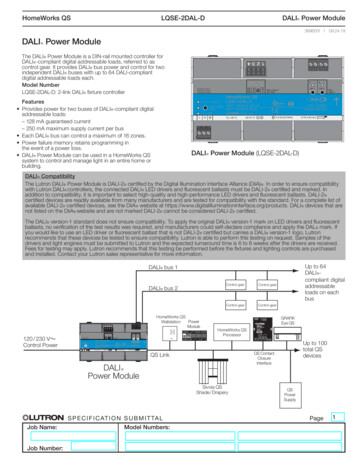
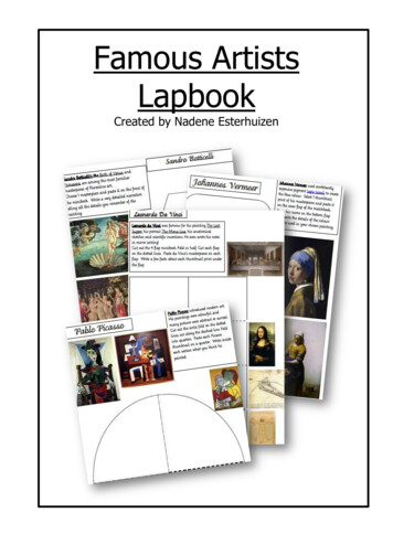
The History of DALI & DSIIn the 1980s there was a strong requirementto make commercial lighting more controllableso that it could become more energy efficient.Initially this was done with analogue control,allowing fluorescent ballasts to be controlledfrom a central source. This was a step in theright direction, but cabling was complicatedand therefore not cost effective.Tridonic was the first company to go digitalwith their broadcast protocol, DSI, in 1991.DSI was a basic protocol as it transmittedone control value to change the brightnessof all the fixtures attached to the line. Whatmade this protocol more attractive, and ableto compete with the established analogueoption, was the simple wiring.A DSI circuit requires only two wires and thefixtures are connected serially, reducing theamount of cabling compared to analogue.In addition the specification of the cablewas relatively low tech (compared to DMX)and even the polarity was not an issue. Thisallowed people with no formal training in DSIto do the installation and achieve a controllablesystem.This satisfied the initial requirement of centralcontrol that was also cost effective. However,as the protocol was owned by Tridonic, othercompanies were unwilling to use it. Anotherlimitation was the lack of individual control.In the late 1990s a controls group, DALI-ag,was set up to design an industry-wide opendigital protocol for the commercial lightingmarket. The members of this working groupwere made up of people from companiessuch as Osram, Tridonic and other leaders inthe commercial lighting world.The requirements were:1. Low cost, simple wiring2. Individual Control3. Feedback from the fixtures4. Ability to add sensors and other proprietaryequipmentThe DALI GuideVersion 3-3DALI was released in 2001 and becamewidely adopted. Since then, its popularity hasincreased and it is now used in more thanjust commercial lighting - so much so thatit is becoming commonplace to have DMXand DALI systems integrated for centralisedcontrol.For more details, s DSI and DALI are very similar, this guidewill concentrate mainly on the DALI protocol.The physical system can be considered thesame, but the data differs as DSI can onlytransmit broadcast values.Why DALI?DALI was created to provide central controlover fixtures, enabling commercial lightingto become more efficient. While the initialdevelopment focused on fluorescent ballasts,applications now encompass a range ofdevices such as LED drivers, HID and lowvoltage halogen.Also, it’s not just lighting - for example, theArtistic Licence daliSwitch product is a DALIcontrolled 6-channel mains relay. In the future,we can expect to see rotaries, light sensorsand more.DALI stands for Digital Addressable LightingInterface. It is technically managed under IEC62386.Overview of a DALI SystemThere are four main components required fora DALI subnet (a subnet or circuit is the DALIequivalent of a DMX universe).1. A DALI controller (may be a gateway, hubor router)2. A DALI Bus Power Supply3. Some kind of DALI device4. CablingThe system in Figure 1 can be consideredone subnet of DALI.yy A DALI subnet can have up to 64 DALIdevices/ballastsPage 4
yy A DALI Bus PSU must always be presenton each DALI subnetThere are a number of limitations to DALI thatrestrict its applications:yy Each device has a short address (0 to 63)yy Slow speedyy There should be no duplicate shortaddressesyy Relatively low number of devices on asubnetyy Each device can be assigned to any of the16 groupsyy Type of DALI equipment on the marketyy Each device can have 16programmed into its memoryPhysical ConnectionsscenesFigure 1: Basic DALI SystemDALI ControllerIn terms of cabling and topology, there aredistinct differences between DMX and DALI.DALI TopologyDALIWhile DMX is cabled on a strict daisy chainsystem, DALI is a simple bus that can go indifferent directions and split into branches.DSI has the same physical connections asDALI.DALI allows many different kinds of cablingschemes, although for traceability it is alwaysrecommended that a logical approach is taken.Below are two example of cabling approachesthat can be used (“D” represents Device).DALI Bus PSUDDALIDDDDeviceDDDeviceStar ConnectionsDeviceTypical ApplicationsDALI can be used in any environment thatrequires central control over lighting fixtures.The most common applications are:yy Commercial office lightingyy House lighting in theatresyy Public building lighting (such as hospitals,airports etc.)The DALI GuideVersion 3-3DDDDDDSerial TypeCable TypeStandard 2-core cable of minimum gauge1.5 mm2 is recommended. The total cablingdistance should be limited to 300 m.Page 5
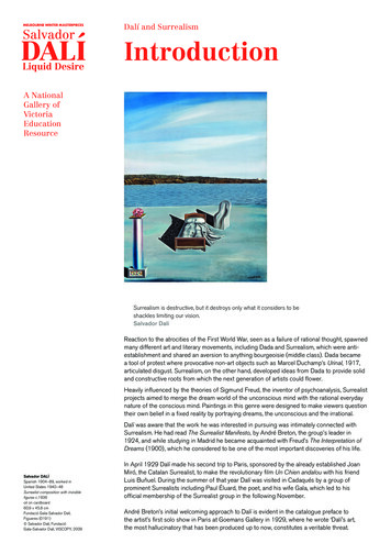
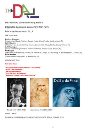
DMXControllerDevicesPolarityDevice 1Device 3Device 4DALIDevice 2Max 300 mDALI specifies polarity-free installation. Thismakes installation easier because the controlcables do not need any kind of identification(the two cores can be put into any terminal).On the majority of equipment the terminalsare identified with the same text.DALIControllerDALI BusPSUDALITo minimise voltage drop on the cable, theDALI Bus PSU can be installed at the middleof the system so the cable is split into twoequal lengths (see Figure 2).Figure 2: Comparison of DMX and DALIsystemsDMXThe total device current consumption shouldnot exceed 250 mA. The voltage drop mustnot exceed 2V anywhere on the system.Device 31DALI Bus PSUIn the DALI specification, power and data arecarried on the same pair of wires.Electrically, the voltage on the line is toggledat high speed between low (logic level ‘0’)and high (logic level ‘1’) to achieve datacommunication.Unlike DMX, the DALI controller does nothave to provide the voltage on the line, so anexternal DALI Bus PSU is generally required(unless the controller has an integrated PSU).Artistic Licence offers Rail-PSU-D4, a fourcircuit power supply. The DALI specificationrequires that the DALI PSU should providea voltage of 16V and is current-limited at250mA.The DALI GuideVersion 3-3Device 32TerminatedTo achieve the logic levels of ‘0’ and ‘1’ thetransmitting device (controller or fixture) willshort the DALI lines together creating a logiclow level – ‘0’. When it is not shorted thelogic level will be high – ‘1’. This is one of thereasons why the PSU needs to be limited to250 mA.The main reasons why DALI is arranged inthis manner are:1. It allows greater flexibility in the wiringof the system as the PSU can be at thecentre of the subnet to minimise voltagedrop. It might not be possible to put thecontroller at the centre.Page 6
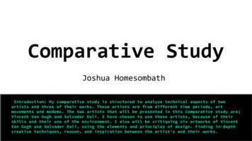
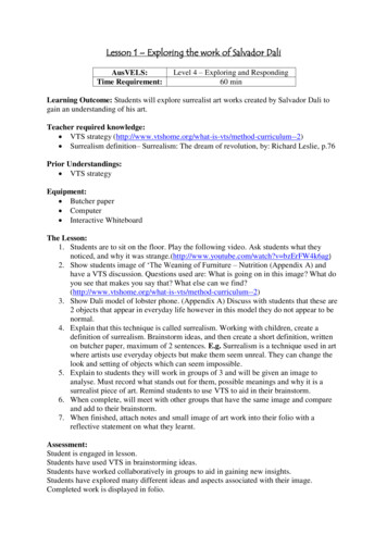
2. The arrangement can reduce voltagedrop.3. Sensors can be powered from the DALIline.Without the power supply, there is nocommunication as the DALI devices interpretthis as a fault condition and go into a faultstate.Electrical SignalsEarthMains - NeutralMains - LiveTo achieve the flexibility in the wiringspecification, the voltage used forcommunication needs to be higher than otherprotocols to compensate for the voltage dropthat might occur.The DALI specification states;yy High Logic Value shall be 16V (9.5V to22.5V DC)yy Low Logic Value shall be 0V (-4.5V to 4.5V DC)yy A 2V difference is allowed between PSUand end of cableyy The nominal voltage is 16VDevicesDALIControllerPSUData StructureDALI is a serial protocol based on ManchesterCoding. It has a baud rate of 1,200 bits persecond (in comparison, DMX has a baud rateof 250,000 bits per second).A DALI controller can send differentcommands to a fixture and therefore needsa different method to DMX to achieve this.Below is the simplified packet that DALI uses.DALIAddress(who)DALIDALI BusPSUCommand(what)Data(how much)A DALI controller will send a packet for everychange it needs to make. The first part ofthe packet is the short address of the fixture,unless it is broadcasting its message. Thesecond part is the type of command andfinally the third part is the value (this is notalways needed).This allows the controller to send a vastnumber of different commands - such as level,discovery and queries - to a device using thesame structure.CommissioningAll DALI devices need to be commissioned forthe first time before they will work correctly.This requires specialised equipment, such asDali-Scope (see below).Figure 3: Complete DALI system withelectrical wiringThe DALI GuideVersion 3-3Commissioning involves giving every DALIdevice a unique short address. This is toPage 7
allow two-way communication between thecontroller and devices.Normal Discoveryfor Pre-AddressedDevicesCommissioningDiscovery sentNew Devices foundwith RandomAddressesIf new devices are added to an existingnetwork, short addresses already in use willbe avoided.New Devicesgiven new shortaddressesThe commissioning process is separate to theconfiguration of the devices and only needsto be done once.Verification ofAddressAssignments sentDALI Commissioning ToolsSimilarly to RDM, a specialised programmingtool is required to commission DALIdevices. There are not many on the marketas commissioning is usually done by acommissioning company. However asDALI becomes more widely used, moreprogramming tools are becoming available.Commissioner daliCommissioner dali is small handheld DALI commissioning tooldesigned by Artistic Licence.It is capable of performingauto-discovery, commissioning,programming, channel, groupand scene assignments, test andanalysis functions.Tridonic USB DALI Interface/ProgrammerThis tool provides all the functions requiredfor DALI commissioning and programming.It also has a detailed Data Monitor that canbe useful to track down issues with DALIcontrollers. Requires a PC.The DALI GuideVersion 3-3Used addressesstoredDALI devices contain a random numbergenerator that enables them to be individuallydiscovered during commissioning. After thecommissioning tool performs the discoverystage, it sequentially assigns individualshort addresses to each device on the DALIsubnet. At the end of the process, the devices’short-addresses can be reprogrammed ifrequired to achieve a more logical order. (Thecommissioning tool will normally identify theballast to be reprogrammed by switching it onor off).System Connected,Controller disabledReport onCommissioningFigure 4: Commissioning FlowchartDALI CommandsWhen controlling ballast/device levels, thereare four commonly used addressing modes.These are:yy Broadcast – A broadcast message can besent to all devices to respond to the givenvalue, e.g. Broadcast 50%yy Channel – Individual control over the 64separate devices (Values: 0% to 100%)e.g. Channel 32 @ 100%yy Group – Each device can be assigned toany of 16 groups. It can be assigned tomore than one group, e.g. Group 10 @95%yy Scene - Every device can store up to 16scenes that can be controlled via a singlecommand, e.g. Scene 2 GoPage 8
Only one command can be sent per packet so,in order to refresh all 64 devices with differentvalues, 64 separate commands must be sent.This can take up to a second, so DMX-stylefast dimming cannot be achieved. Instead,DALI allows a fade time to be specified.Light output levels are commonly referred toas percentages (fluorescent lamps usuallyhave low resolution fade profiles which do notrequire the precision of a decimal number).Table 1 below lists the DALI commands thatare commonly used. Several of these can besent to individual channels or broadcast to theentire subnet.A key feature of DALI is its ability to getinformation back from the ballasts; therefore,some commands can be queries or ‘set’instructions.Note that DALI commands that are used fordiscovery and programming are not includedin Table 1.CommandDirect Arc ValueOffUpAddressing ModeBroadcast / Groups / ChannelsBroadcast / Groups / ChannelsBroadcast / Groups / ChannelsDownBroadcast / Groups / ChannelsStep UpBroadcast / Groups / ChannelsStep DownBroadcast / Groups / ChannelsRecall Max LevelRecall Min LevelStep Down and OffOn and Step UpGo to Scene xStatusBroadcast / Groups / ChannelsBroadcast / Groups / ChannelsBroadcast / Groups / ChannelsBroadcast / Groups / ChannelsBroadcast / Groups / ChannelsChannelsDeviceLamp Power OnVersion NumberDevice TypeActual LevelMax LevelMin LevelPower On LevelSystem Failure LevelFade Time / Fade RateScene sSend direct level valuesSend the off commandIncrease value by 1 until MaxLevel, honouring the fade timeDecrease value by 1 until MinLevel, honouring the fade timeIncrease value by 1 until MaxLevel, ignoring the fade timeDecrease value by 1 until MinLevel, ignoring the fade timeOutput Max ValueOutput Min ValueDecrease value by 1 /Turn offTurn on / Increase by 1Go to Scene CommandIs there a Device using thisShort Address?Status of the DeviceIs the Lamp on?Replies: Current VersionReplies with the device typeQuery Current LevelQuery or SetQuery or SetQuery or SetQuery or SetQuery or SetQuery or SetTable 1: Common DALI CommandsThe DALI GuideVersion 3-3Page 9
DMX and DALI as PartnersWith increasing crossover between theentertainment, architectural and commerciallighting sectors, environments that requireintegration between DMX and DALI equipmentare becoming more common.Careful planning is required as a numberof issues must be considered to ensure asuccessful system. These include the speeddifferences between the two protocols, thetype of control, dimming curves and thecommissioning of fixtures.DMX-to-DALI ConversionThere are situations in which one would liketo control DALI ballasts with a DMX controllerthat is simultaneously being used to controlDMX fixtures. An example would be a lightingdesk in a theatre that is also used to dim thehouse lights.DALI-to-DMX ConversionConversely, there are also situations inwhich it is useful to convert DALI into DMX.Consider the following scenario:A cinema foyer contains an existing DALIcontroller which is being used to controlwhite fluorescent overhead lighting. Thecustomer wishes to use it to control somenew DMX colour-changing lights that arebeing installed in the foyer. Additionally,there is a media wall on the outside of thebuilding, which is being run by a dedicatedDMX controller. The customer would like tobe able to trigger shows on the media wallfrom the DALI controller located in the foyer.DALItoDMXAll the above-mentioned functionality can beachieved using the Artistic Licence product,DALItoDMX, in conjunction with the existingcontrollers.DMXtoDALI quadDALIIn such scenarios, a conversion product suchas DMXtoDALI quad from Artistic Licenceprovides a convenient solution.DMX RGB FixturesDALIControllerRail-PSU-D4DALIDMXtoDALI quad converts packets from aDMX controller to DALI commands, enablingcontrol of up to four circuits of 64 DALI ballastseach.The product supports DALI discovery toidentify devices on the network, and enablesballasts to be controlled with the usualBroadcast, Channel, Group and Scenecommands.Given the speed differences between DMXand DALI, best results tend to be achievedby sending the lowest number of commands- the Scene command is particularly efficientin this regard, as it enables all the ballasts ona circuit to change using only one command.The DALI GuideVersion 3-3DALItoDMXDMXBallast ModeDMX record/playback unitTrigger ModeDMXFigure 5: Data flow for DALItoDMX inBallast and Trigger ModesPage 10
The product has two modes of operation,Ballast or Trigger, as shown in Figure 5 onthe previous page. Ballast mode is used tocontrol the DMX colour-changing lights, whileTrigger mode is used for the media wall.In Ballast Mode, DALItoDMX simulates virtualballasts, each of which has control over asingle DMX channel. The usual Broadcast,Channel, Group and Scene commands aresupported, and the product offers a choice of1, 4, 16 or 64 virtual ballasts.In Trigger mode, the DALI commands serveas data streams that enable sophisticatedtriggering options.Dimming CurvesThe majority of DMX devices operate using alinear dimming curve with the level selectedby a decimal value between 0 and 255.DALI works with a non-linear (exponential)curve. As the graph shows, each methodproduces a different output.CircuitCommissioningDALIDALI Bus PSUDeviceDMX512DSIGatewayGroupBallast Power100%HubDMXDALI0Router0Control Value255DMXtoDALI quad and DALItoDMX offer theability to translate between the two curves.SceneShort AddressGlossary of TermsBallastBusThe DALI GuideTechnically, a driverfor a light source thatcommunciates using DALI.Often taken to mean thelight source itself. Usedinterchangeably with Device.The wire that data travelsdown.Version 3-3SubnetA single DALI line - seeSubnet.The phase that sets up DALIdevices for the first time toenable them to be used in aDALI subnet.Digital Addressable LightingInterfaceA PSU that must be presentfor DALI communication.These are often separate tothe controller. Ideally theyshould be centrally locatedon a DALI bus.DALI equipment - usuallya light or a sensor. It willrequire one short address.See also Ballast.Lighting Protocol usedin Entertainment styleapplications.Digital Signal InterfaceA device that allows datatransmission betweendifferent systems (see alsoHub and Router).A collection of devices thatcan respond to the samecommandA device that allows datatransmission betweendifferent systems (see alsoGateway and Router).A device that allows datatransmission betweendifferent systems (see alsoGateway and Hub).A level held in devicememory that can be recalledwith a ‘Scene’ commandThe indentification numberof a DALI device - must beunique on the network andbetween 0 and 63Synonymous with Circuit.It comprises the DALIcontroller, a DALI Bus PSUand the device(s).Page 11
DALI Specificationyy Cable- maximum distance: 300 m- minimum gauge: 1.5 mm2- two-wire systemyy Maximum number of devices: 64yy Polarity - Noneyy Serial Communication- Baud rate: 1200 baud- Serial Data: 8 bits, 1 start bit, 4 stop bits- Manchester codingyy PSU- Nominal voltage: 16V- Maximum voltage drop allowed: 2V- Maximum supplied current: 250 mAArtistic LicenceThe Mould Making WorkshopSoby MewsBovey TraceyTQ13 9JGUnited KingdomTelephone 44 (0) 20 8863 cLicence.comSupport@ArtisticLicence.comDue to our policy of continuing product improvementspecifications are subject to change without notice
Appendix - LSi Help Desk articlesi TECHhelp deskDALI: Trials & Tribulations By Wayne Howellmanufacturer in an ‘un-commissioned’ state.Commissioning is the process by which each ofthese fixtures is assigned a number in the range1-64 (the so-called ‘short-address’). This shortaddress is used by the controller to individuallycontrol each fixture.In almost all situations, you will need tocommission the DALI fixtures before the controllercan do anything. The commissioning process isnot complex, simply connect a commissioningtool to the DALI circuit and press the button.There is one situation where commissioningis not essential: if the DALI controller does notneed individual control and all the fixtures areto be controlled as a group. In this situation,the controller can operate in broadcast modeand commissioning is not needed.Ten years ago, DALI was nota lighting control protocol thatregularly came up on my radar.DMX512 was king and DALI was perceived as acheap solution for switching fluorescent lamps.Today, my company, Artistic Licence,ships the same quantity of DMX512 and DALIinfrastructure products. So what changed? Theanswer can be simply put as ‘convergence’. Wehave seen the commercial and retail marketsconverging with the feature and theatricalmarkets. It is now perfectly normal for a theatreto want to control their DALI house lights fromthe lighting console. Equally, a corporate foyerwith DALI controlled lights may well need totake control of a DMX512 fixture.From a technology perspective this is all very‘do-able’. What has not kept pace is knowledgeand education for specifiers and installers. It is fairto say that our support desk sees a much higherlevel of DALI questions compared to DMX512 - andthe questions seem to repeat. This article distilsthe regular questions and hopefully will providea cheat-sheet for installers and specifiers . . .POWERThe single biggest cause of confusion with DALI is the bus powersupply. DALI controllers can be thought of as similar to volt-freerelays. The controller is sending data by repeatedly shorting the twowires together. Absolutely no data will travel over those wires unlesssomeone connects a voltage, and this is the purpose of the buspower supply. It is a 16V DC power supply designed witha special current limiting circuit. A DALI circuit must have a buspower supply connected somewhere. There are no exceptions - it willnot work otherwise. The good news is that the bus power supply canbe attached anywhere on the DALI circuit. It may even be built in tothe DALI controller - so you need to check the user guide.When looking at a system drawing for a DALI installation,expect to see three categories of power supply. There should bepower for the fixtures. There should be a DALI bus power supply.And there should be a power supply for the DALI controller.Sometimes these are merged together, but if you count fewerthan three power supply categories - be sure you know why!CONVERSIONThe next most frequent support issue is usually phrasedsomething like: “The fades seem awfully steppy . . .”DALI is over 200 times slower than DMX512. It was notdesigned for subtle, real-time colour mixing. If you try to makea simplistic conversion from DMX512 to DALI and run bigcolour wave effects, it will look rubbish!That is not to say you can’t link DMX and DALI, you certainlycan. But it requires some planning. DALI has some cleveraddressing modes called groups. Each DALI circuit has16 groups and they can be controlled fairly quickly. Whenconverting DMX512 to DALI, think in terms ofeither broadcast or group addressing.COMMISSIONINGThe phrase that sends shivers through oursupport team is “So what is commissioningthen”?Each DALI circuit can contain up to 64fixtures. These fixtures will be supplied by the72APRIL 2017 WWW.LSIONLINE.COMCABLE & POLARITYThe cable used for DALI is not specialist - youcan use mains cable. The maximum distanceis 300m but the gauge of the cable needs toincrease as distance increases. Using 1.5mm2will cover most situations.DALI is polarity independent. The two wirescan be connected either way around.ADDRESSING MODESI mentioned the DALI group addressing modes earlier, but it isuseful to have an overview of DALI addressing when designingan installation. For those familiar with DMX512: DALI is totallydifferent. DMX512 is a streaming protocol, which means that all512 channels are continuously refreshed. DALI is a vector protocolwhich means that commands are sent to a fixture when a changeoccurs. DALI has four different methods of sending data to the 64fixtures that can be connected to a DALI circuit, as follows . . .Scene: It is important to understand that the designers ofDALI viewed it as a system where commands would be issuedand fixtures would respond. Scene control underlines thisconcept. Each fixture can be programmed to hold levels for upto 16 different scenes. The controller can then trigger replay ofthose scenes with variable fade rates. This is the most effectiveDALI addressing mode as it requires very little bandwidth.Broadcast: DALI evolved out of earlier and simpler protocols.Broadcast addressing is how those earlier protocols (such asDSI) worked. Essentially, all fixtures will follow each other. Thisdoesn’t give much artistic freedom, but is very useful when youjust want to set the level of all fixtures in one room. It is verybandwidth efficient and so provides very responsive control.Channel: This allows the controller to set the level of each ofthe 64 possible fixtures individually. This is a very bandwidthintensive process and trying to use this for real-time effects willalmost certainly not give good results.Group: All of the 64 fixtures can be allocated to any of the 16possible groups. This provides a good compromise betweenBroadcast and Channel addressing. This is themode most widely used when using DALI fordynamic real time effects.Wayne Howell is the CEO of ArtisticLicence, the lighting controlscompany that he founded in 1988.Wayne invented Art-Net andis actively involved in the ESTAtechnical standards programme.SUMMARYArtistic Licence has written a DALI Guidewhich covers the above in more detail. It canbe downloaded from the link below . . . IP //tinyurl.com/the-dali-guide
i TECHhelp deskDALI & Colour By Wayne Howell“DALI-2 adds additional addresses for control interfaces, which means thatyour control panels no longer need eat into the 64-fixture address space . . .”My first Help Desk column last April covered thebasics of DALI. Since then, DALI has been evolving,and so have the questions asked on our Help Desk.So, now seems like a good time to look at what has changed . . .DALI stands for Digital Addressable Lighting Interface andis a control protocol used widely in architectural andcommercial lighting. It has a number of benefits, such as notrequiring specialist cable, having polarity independent wiringand low cost.For those readers more used to entertainment lightingcontrol with DMX512, DALI has two key drawbacks: it onlycontrols 64 fixtures per circ
DALI stands for Digital Addressable Lighting Interface. It is technically managed under IEC 62386. Overview of a DALI System There are four main components required for a DALI subnet (a subnet or circuit is the DALI equivalent of a DMX universe). 1. A DALI controller (may be a gateway, hub or router) 2. A