Transcription
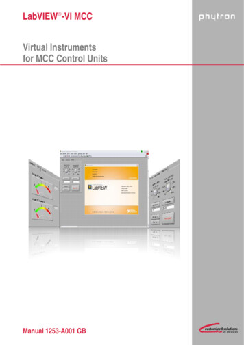
LabVIEW -VI MCCVirtual Instrumentsfor MCC Control UnitsManual 1253-A001 GB
phytronLabVIEW Virtual Instrumentsfor MCC Control UnitsTRANSLATION OF THE GERMAN ORIGINAL MANUAL6/2010Manual MA 1253-A001 GB
Manual LabVIEW -VI MCC 2010All rights with:Phytron GmbHIndustriestraße 1282194 Gröbenzell, GermanyTel.: 49 8142/503-0Fax: 49 8142/503-190Every possible care has been taken to ensure the accuracy of this technical manual. Allinformation contained in this manual is correct to the best of our knowledge and belief butcannot be guaranteed. Furthermore we reserve the right to make improvements andenhancements to the manual and / or the devices described herein without priornotification. You find the updated version of this manual on the website of www.phytron.de.We appreciate suggestions and criticisms for further improvement. Please send yourcomments to the following email address: doku@phytron.deMA 1253-A001 GB4
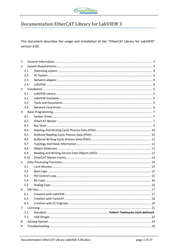
phytronContents1 What is LabVIEW ? . 61.1Requirements . 61.2Extent of Supply . 62 To Consider Before Installation . 72.1Qualified Personnel . 72.2Warning Regarding Use of Software Products . 73 General VI Description . 84 Description of the MCC.llb . 94.1General . 94.2AD-MCC.VI . 94.3COMM-MCC.vi. 104.4Counter-MCC.vi . 104.5Directmode-MCC.vi . 114.6Drive-MCC.vi . 124.7Encoder-MCC.vi . 134.8Init-MCC.vi . 144.9Input-MCC.vi . 154.10Output-MCC.vi . 164.11Parameter-MCC.vi . 174.12Register-MCC.vi . 184.13Status-MCC.vi . 195 Demo-MCC.vi . 205.1General Description . 205.2A/D Inputs and Encoder Timer Reading . 215.3Application for Direct Mode and Motor Driving . 225.4Internal Distance Counter Reading and Displaying . 245.5The MCC Inputs / Outputs Reading / Setting . 255.6Parameters Reading / Writing . 265.7Register Reading and Writing . 275.8Initiator and Controller Status Reading . 286 Parameters. 297 Copyright and Disclaimer of Warranty . 358 Index . 365MA 1253-A001 GB
Manual LabVIEW -VI MCC1 What is LabVIEW ?This manual describes the LabVIEW graphical programming language from NationalInstruments, which uses icons to create the application.LabVIEW stands for „Laboratory Virtual Instrument Engineering Workbench“.LabVIEW programs are called Virtual Instruments or VIs. These VIs content the frontpanel, the user interface and the block diagram. The block diagram is a graphical programcode, which is compiled like other high level programming languages.This manual describes the LabVIEW use for the Phytron controllers MCC-1, MCC-2 andMCC-2 LIN.LabVIEW is a Trademark of National Instruments Corporation. See chap. 7.1.1 RequirementsA well-trained LabVIEW user is expected for using the Phytron MCC controller VIs. Heknows the programming environment. Basic knowledge in programming like data types,loops etc. are required.The MCC VIs are built for LabVIEW 8.0 or higher.1.2 Extent of SupplyThe package contents two LabVIEW libraries: MCC.llbEncloses the VIs to be applied for the MCC controllers Demo-MCC.llb Demo-applications which make the VIs clearMA 1253-A001 GB6
phytron2 To Consider Before InstallationRead all manuals very carefully before installing and operating.Observe the safety instructions in the following chapter!2.1 Qualified PersonnelDesign, installation and operation of systems may only be performed by qualifiedand trained personnel.These persons should be able to recognize and handle risks emerging fromelectrical, mechanical or electronic system parts.The qualified personnel must know the content of this manual and be able tounderstand all documents belonging to the product. Safety instructions are to beplanned.The trained personnel must know all valid standards, regulations and rules for theaccident prevention, which are necessary for working with the product.WARNINGWithout proper training and qualifications damages to devices and injury mightresult!2.2 Warning Regarding Use of Software Products1. In any application the reliability of operation of the software products can beimpaired by adverse factors, e. g. differences in electrical power supply or,computer hardware malfunctions.To avoid damage by system failures the user must take appropriate safetymeasures, including back-up or shut down mechanism.2. Malfunctions are possible while programming the instruction codes – e. g.sudden run of a connected motor, braking etc.Please test the program flow step by step!3. Each end user system is customized and differs from the testing platform.Therefore the user or application designer is responsible for verifying andvalidating the suitability of the application.7MA 1253-A001 GB
Manual LabVIEW -VI MCC3 General VI DescriptionLabVIEW programs are called virtual instruments or VIs.Every VI can be used as a stand-alone program or as a subroutine called sub VI.The user defines the data flow by connecting the VIs with connection lines (wires).The VI executes when all input data are available.If the complete VI is finished, the results will be on the outputs. The sequence of theexecution is defined by the dependency of the data. There is no predefined sequence(e. g. from right to left).MA 1253-A001 GB8
phytron4 Description of the MCC.llb4.1 GeneralInputs and outputs which are the same for all VIs in the library:NameI/OMeaningVISA resource name inInputTransfer of the interface parametersError inInputInput of the error clustersVISA resource name outOutputDisplay of the interface parametersError outOutputOutput of the error clusterInputs and outputs have the same function. They are only described once.A cluster is the bundling of different data types in LabVIEW. It can be used as an input oroutput.4.2 AD-MCC.VIRead the A/D value of the MCC.This VI provides the current A/D converter value as a 16-bit unit to the output whileexecuting.Fig. 1: AD-MCC.viNameI/OMeaningAddressInputAdjusted address at the controller (0 -15 8-bit unit)ChannelInputChannel of the A/D converter, which should be read(1 or 2, 8-bit unit)A/D ValueOutputA/D value in increments (0 – 1023, 10-bit)9MA 1253-A001 GB
Manual LabVIEW -VI MCC4.3 COMM-MCC.viThis VI is internal used by other VIs. It should not be applied for programming user specificapplications.4.4 Counter-MCC.viThis VI reads the selected axis counter.It displays the counter value of the selected axis by reading the parameter 20 (P20).You ll find the parameter description in chapter 6.Fig. 2: Counter-MCC.viNameI/OMeaningAddressInputAdjusted address at the controller (0 -15 8-bit unit)AxisInputThe counter of the axis should be read(1 or 2, 8-bit unit)Counter ValueOutputCounter value of the axis (Double)MA 1253-A001 GB10
phytron4.5 Directmode-MCC.viAn instruction is transmitted to the controller.The VI transmits the string at the input Send String to the controller and picks up theanswer from the controller.For detailed description of the controller commands see chap.6.Fig. 3: d address at the controller (0 -15 8-bit unit)Send StringInputCommand, which is transmitted to the controller(e. g. X 1000 corresponds to drive 1000 steps)Transmission OKOutputTrue, if the controller acknowledged the command (ACK)False, if the command was invalid (NAK)Receive StringOutputAnswer string of the controller (without control characterand ACK)It s empty when the commands have no response.11MA 1253-A001 GB
Manual LabVIEW -VI MCC4.6 Drive-MCC.viThis VI sends drive instructions to the MCC.This functional module reads the values adjusted in the cluster and generates a driveinstruction for the MCC.Fig. 4: Drive-MCC.viNameI/OMeaningCluster:InputIt has the following data types:Axis Axis (8-bit unit): axis, where the drive instruction isdisplayed (1 or 2)Address Address (8-bit unit): Controller address (0-15)Position Mode Position Mode (ENUM): the following adjustments areavailable:o Relative, generates and transmits a relative driveinstructiono Absolute, generates and transmits an absolutedrive instructiono Initialization Plus, generates and transmits aninitialization toward the positive directiono Initialization Minus, generates and transmits aninitialization toward the negative directiono Free Run Plus, starts a free run toward the positivedirectiono Free Run Minus, starts a free run toward thenegative direction Distance (DLB): this input is used as a distance forrelative and absolute drive instructionsDistanceTransmission OKMA 1253-A001 GBOutputTrue: the controller accepts the instructionFalse: invalid command12
phytron4.7 Encoder-MCC.viThe encoder counter reads the selected axis.Parameter 22 (P22) is read out for the corresponding axis.You ll find the description of the parameters in chapter 6 parameters.Fig. 5: Encoder-MCC.viNameI/OMeaningAddressInputAdjusted address at the controller(0 -15 8-bit unit)AxisInputThe count of the axis is to be read (1 or 2, 8-bit unit)Encoder ValueOutputRead Encoder value of the axis (Double)13MA 1253-A001 GB
Manual LabVIEW -VI MCC4.8 Init-MCC.viThis VI displays the initiator status.The MCC initiator status is imported and displayed as Boolean Cluster.Fig. 6: Init-MCC.viNameI/OMeaningAddressInputAdjusted address at the controller(0 -15 8-bit unit)Cluster:Initiator StatusOutputThe Initiator Status consists of four elements (BOOL) Axis 1 , activated TRUE, free FALSE Axis 1-, activated TRUE, free FALSE Axis 2 , activated TRUE, free FALSE Axis 2 -, activated TRUE, free FALSEMA 1253-A001 GB14
phytron4.9 Input-MCC.viReads the MCC input status.The status of the MCC is displayed as a Boolean Cluster.Fig. 7: Input-MCC.viNameI/OMeaningAddressInputAdjusted address at the controller(0 -15 8-bit unit)Cluster: InputsOutputInputs, consist of eight elements (Boolean)TRUE Input HighFALSE Input Low15MA 1253-A001 GB
Manual LabVIEW -VI MCC4.10 Output-MCC.viThis VI sets the outputs at the MCC.The status at the input is set as output status during execution.Fig. 8: Output-MCC.viNameI/OMeaningAddressInputAdjusted address at the controller(0 -15 8-bit unit)Cluster: OutputsInputOutputs, consist of eight elements (Boolean)TRUE Output HighFALSE Output LowTransmission OKMA 1253-A001 GBOutputTrue: the controller accepts the instructionFalse: invalid command16
phytron4.11 Parameter-MCC.viThis VI reads or sets the MCC parameters.The MCC reads or transmits the parameter which is adjusted in the Parameter Number.Fig. 9: Parameter-MCC.viNameI/OMeaningCluster:InputIt has the following data types:Address Address (8-bit unit): controller address (0-15)Axis Axis (8-bit unit): Axis, of which the parameter isread/written (1 or 2)Parameter Number Parameter Number (8-bit unit): Parameter numberto be read or written Parameter Value (Double): Parameter value to bewritten. Only with the choice ‚write‘! Read / Write (Enum):Contains the items Read and Write.Read: Parameter is read and is displayedat the Parameter Value output.Write: Parameter is written with the value fromthe Parameter Value input.Parameter ValueRead / WriteTransmission OKOutputTrue: the controller accepts the instructionFalse: invalid command(Boolean)Parameter ValueOutputThe Read function displays the parameter value of theselected parameter (Double).17MA 1253-A001 GB
Manual LabVIEW -VI MCC4.12 Register-MCC.viReads or sets the MCC register.The register set in Register Number is read or transmitted to the MCC.Fig. 10: Register-MCC.viNameI/OMeaningCluster:InputIt has the following data types:Address Address (8-bit unit): controller address (0-15)Register Number Register Number (16-bit unit): Register number, to beread or written.Register Value Register Value (Double): Register value to be written.Only with the choice ‚write‘!Read / Write Read / Write (Enum):Contains the items Read and Write.Read: Parameter is read and is displayedat the Register Value output.Write: Parameter is written with the value fromthe Register Value input.Transmission OKOutputTrue: the controller accepts the instructionFalse: invalid command (Boolean)Register ValueOutputThe Read function displays the register value of theselected parameter (Double).MA 1253-A001 GB18
phytron4.13 Status-MCC.viReads the MCC status and displays the result as Boolean Cluster.Fig. 11: Status-MCC.viNameI/OMeaningAddressInputAdjusted address at the controller(0 -15 8-bit unit)Cluster: StatusOutputDisplays the MCC status as Boolean cluster.The status is read binary.You ll find further information in the MINILOGProgramming Manual for MCC available under theSB instruction.19MA 1253-A001 GB
Manual LabVIEW -VI MCC5 Demo-MCC.vi5.1 General DescriptionThe VI demos use the VIs from the MCC.llb. These are demos of register cards withdifferent tabs.The first register card (Settings) is equal in all demos and only described once.Settings of the register card:Here general settings for the interface are made:COM PortConfigures the used interface.In this case the serial interface COM4.AddressThe Address adjusted at the controllerBaud RateConfiguration of the controller s baud rate, e. g. 57 600.TimeoutThe time waiting for an answer.If there is no answer in the specified time, VISA-VI outputs an error.ErrorThis output displays an error message, which occurs duringcommunication.StopStops the program.MA 1253-A001 GB20
phytron5.2A/D Inputs and Encoder Timer ReadingThis demo has one register card with three tabs: Settings, A/D and Encoder.(For the description of Settings register card please see above.)A/D register card:This register card shows the present voltage at channel 1and 2 of the MCC A/D inputs.These are both graphically displayed as well as a number in the text box.Encoder register card:The MCC encoder counters and the counter value are imported and displayed in the textboxes.21MA 1253-A001 GB
Manual LabVIEW -VI MCC5.3Application for Direct Mode and Motor DrivingThis demo is a small application to demonstrate- Directmode-MCC.vi- Parameter-MCC.vi and- Drive-MCC.vi files.Direct Mode register card:Send StringInput of the transmitting commandSendTransfer of the commandReceive StringDisplay of the MCC answerTransmission OKCommand recognized:LED on (ACK)command not recognized: LED off (NAK)MA 1253-A001 GB22
phytronOperation register card:Velocity Hz (P14)Sets the driving speed of the MCC. Free Run or – enables tochange the velocity also during the run.Ramp Hz/S (P15)Sets the acceleration- and axes ramp. The value can only betransferred when the motor is at a standstill.Go RelativeMoves from the actual position by entered value (textbox).Go AbsoluteMoves the entered value (textbox) referred to the zero point.Free Run Starts a free run toward positive directionFree Run -Starts a free run toward negative direction! Motor STOP !Cancels each running positioning and stops the motor.23MA 1253-A001 GB
Manual LabVIEW -VI MCC5.4Internal Distance Counter Reading and DisplayingThis demo reads the internal MCC distance counter (P20) and displays it as a countervalue as well as a diagram.Counter register card:Counter Value Axis 1Counter value display of axis 1 (X)Counter Value Axis 2Counter value display of axis 2 (Y)ResetDeletes the graphXY GraphDiagram of the varying counter value at axis 1 and in the systemof coordinates.MA 1253-A001 GB24
phytron5.5The MCC Inputs / Outputs Reading / SettingThis demo reads and displays the MCC inputs and activates the outputs.I/O register card:InputsDisplay of the MCC input status:LED on Status HighLED off Status LowOutputsThe respective MCC outputs can be switched.25MA 1253-A001 GB
Manual LabVIEW -VI MCC5.6Parameters Reading / WritingThis demo reads and writes the MCC parameters.Parameter register card:Read/WriteReading or writing the parametersAxisAxis, whose parameters are changedParameter Number Parameter number, which is modifiedParameter Value(Write Only)Value to which the parameter is changed (write only)Parameter ValueRead parameter of the controller ( read only)MA 1253-A001 GB26
phytron5.7Register Reading and WritingThis demo reads and writes the MCC Register.Read/Write Registers register card:Read/WriteReads or writes the registersRegister NumberRegister number which is read or writtenRegister Value(Write Only)Value that is written in the register. (write only)Register ValueValue that is written out of the register. (read only)27MA 1253-A001 GB
Manual LabVIEW -VI MCC5.8Initiator and Controller Status ReadingThis demo reads and displays the initiator status and the general MCC status.Status register card:Initiator StatusInitiator status of the controller.The LED is on, when the initiator is activated.The SUI command is used.StatusGeneral status of the controller.The LEDs display the status.The SB command is used.The LED colors are described in the MiniLog Programming Manual.MA 1253-A001 GB28
phytron6 ParametersFor operating a stepper motor controller different presettings as speed, acceleration rampsor waiting time are required which are called Parameters.Default parameters are stored at delivery which can be used in several applications. Youcan read and edit these parameters with LabVIEW Parameter-VI or MiniLog-Comm.Counters also belong to the list of parameters, which will be continuously actualized by theprogram. The counters can be read and some of them can be edited, too. For each axis separate parameters have to be set. Insert an X or Y to mark the axis infront of the parameter number (also valid: 1 or 2).Example: XP15 is the acceleration ramp value for axis X. Parameters (e.g. speeds) may be modified several times within a program, too. Parameter values can be entered or read. P48 and P49 can only be read. P19 to P22 are counters. They will be actualized by the program during axismovement. P27 to P49 are special parameters for MCC-2.29MA 1253-A001 GB
Manual LabVIEW -VI MCCList of ParametersNo. MeaningDefaultP01 Type of movement0 rotationalRotating table, 1 limit switch for mechanical zero(referencing)1 linearfor XY tables or other linear systems,2 limit switches:Mechanical zero and limit direction –Limit direction 0P02 Measuring units of movement1 step2 mm3 inch4 degree1P03 Conversion factor for the thread1 step corresponds to .1If P03 1 (steps) the conversion factor is 1.Computing the conversion factor:Conversion factor ThreadNumber of steps per revolutionExample:4 mm thread pitch200-step motor 400 steps/rev. in the half step modeConversion factor 4 0.01400P04 Start/stop frequencyThe start/stop frequency is the maximum frequency tostart or stop the motor without ramp. At higher frequencies, step losses or motor stop would be the result of astart or stop without ramp. The start/stop frequencydepends on various factors: type of motor, load,mechanical system, power stage.400The frequency is programmed in Hz.P05not usedP06P07Emergency stop rampThe frequency is programmed in 4000-Hz/sec-steps.MA 1253-A001 GB30100 000
phytronNo. MeaningDefaultP08 fmax MØP (mechanical zero point)Run frequency during initializing (referencing)4000Enter in Hz (integer value)P09 Ramp MØPRamp during initializing, associated to parameter P084000Enter in 4000-Hz/sec-stepsP10 fmin MØP Run frequency for leaving the limit switch range400Enter in HzP11 MØP offset for limit switch direction 0Distance between reference point MØP and limit switchactivationUnit: is defined in parameter P02P12 MØP offset for limit switch direction –0Distance between reference point MØP and limit switchactivationUnit: is defined in parameter P0220P13 Recovery time MØPTime lapse during initializationEnter in msecP14 fmax Run frequency during program operation4000Enter in Hz (integer value) (40 000 maximum)4000P15 Ramp for run frequency (P14)Input in 4000-Hz/sec-steps (4000 to 500 000 Hz/sec)P16 Recovery time positionTime lapse after positioning20Input in msec31MA 1253-A001 GB
Manual LabVIEW -VI MCCNo. MeaningDefaultP17 Boost (defined in P42)00 off1 on during motor run2 on during acceleration and deceleration rampRemarks:The boost current can be set in parameter P42.You can select with parameter P17 in which situation thecontroller switches to boost current.P17 1 means, the boost current always is switched onduring motor run. During motor standstill the controllerswitches to stop current.P18 not used0P19 Electronically zero counterUsed for setting operating points. At standstill of the axis,P19 can be read or programmed during programexecution.0P20 Mechanical zero counterThis counter contains the number of steps referred to themechanical zero (MØP). Can be read at axis standstill. Ifthe axis reaches the MØP, P20 will be set to zero.0P21 Absolute counterIndicates the true position. At any time P21 can be asked,programmed or modified.P21 is not automatically set to zero when the MØP isreached.P22 Encoder counter0Indicates the true encoder position.P23 Axial limitation pos. direction 0If the number of steps is reached, the run in direction isaborted.0 no limitationMA 1253-A001 GB32
phytronNo. MeaningDefaultP24 Axial limitation neg. direction –0If the number of steps is reached, the run in – direction isaborted.0 no limitationP25 Compensation for play0Indicates the step number, the target position in theselected direction is passed over and afterwards is startedin reverse direction.0 no compensation for playP26 not usedP27 Initiator type00 PNP normally closed contact (NCC)1 PNP normally open contact (NOC)P 28 to P33 not usedP34 Encoder type00 no1 incremental2 serial interface SSI binary Code3 serial interface SSI Gray CodeConnect the correct encoder type!Do not parameterize an incremental encoder asSSI. Danger of damage!P35 Encoder resolution for SSI encoder10Enter max. encoder resolution in bit (max. 31 Bit)P36 Encoder function00 counterP37 not usedP38 Encoder preferential direction of rotation00 (positive)1 – (negative)P39 Encoder conversion factor11 increment corresponds to .33MA 1253-A001 GB
Manual LabVIEW -VI MCCNo. MeaningDefaultP40 Stop current in 0.1 A stepsValues:Input:20 to 2.5 A0 to 25P41 Run current in 0.1 A stepsValues:Input:60 to 2.5 A0 to 25P42 Boost current in 0.1 A stepsValues:Input:100 to 2.5 A0 to 25P43 Current delay time in msec20P44 not usedP45 Step resolution 1 to 2561 Full step2 Half step4 1/4 step8 1/8 step410 1/10 step16 1/16 step128 1/128 step256 1/256 stepP46 Current Shaping (CS), also see appendix A10 Off1 OnRecommended setting: P46 1P47 Chopper frequency0 low11 highThe chopper frequency value depends on P46:If P46 0, then is applied: P47 0:16 kHzP47 1: 22.5 kHzIf P46 1, then is applied:P47 0:P47 1:Recommended setting:P47 150 kHz75 kHzP48 Power stage type (read only)(read only)0 linear 1 chopperP49 Power stage temperature in C (read only)(only for linear power stage type)MA 1253-A001 GB34(read only)
phytron7 Copyright and Disclaimer of WarrantyThe LabVIEW communication software and its documentation are protected by copyrightlaw. The manual must not be copied, reproduced, put into machine readable form, neithercomplete nor in parts, without the prior written permission of National InstrumentsCorporation. It is permitted to create backups of the Phytron Freeware VIs for personaluse. However, the program must not be modified or sold.Disclaimer of warrantyThe Phytron specific VIs and the associated manual were made with great care andreproduced with the involvement of effective control measures. Each CD-ROM is checkedbefore delivery with a well-known scanner program for viruses of all kinds. Neverthelesserrors can exist.Phytron does not warrant that the software is free of errors.Phytron is not liable for any damages arising by using this software. The user orapplication designer is ultimately responsible for the suitability of the software.We refer to our terms of delivery and payment, in particular to item VII liability and item IXsoftware use.You’ll agree to our delivery and payment conditions by installing, copying or using thesoftware otherwise. If you disagree to these conditions you aren’t authorized to install oruse the software.TrademarksIn this manual several trademarks are used which are no longer explicitly marked astrademarks within the text. The lack of this signs may not be used to draw the conclusionthat these products are free of rights of third parties.Some product names used herein are for instance: Microsoft is a registered trademark and WINDOWS is a trademark of theMicrosoft Corporation in the USA and other countries. LabVIEW is a registered trademark of National Instruments Corporation.35MA 1253-A001 GB
Manual LabVIEW -VI MCC8 IndexALA/D converter 9A/D Inputs 21LabVIEW 6Limit switch 30BMBoolean Cluster 14, 15MCC.llb 6MINILOG 19COCluster 9Compensation for play 33Copyright 35Counter 10, 24, 32Operation 23PDParameter 17, 26Parameter Number 17Demo 20Demo-MCC.llb 6Direct mode 22Directmode 11Drive 12Drive instruction 12RRead / Write register 27Register 18Register card 20Register Number 18ESEncoder 13Encoder Counter 21Error cluster 9Settings 20Start-/Stop frequency 30Status 19, 28FTFreeware 35Trademarks 35IVI/O 25Init 14Initiator Status 14Input 15Inputs / Outputs 25Installation 7Interface 29Interface parameter 9MA 1253-A001 GBVI 6Virtual instruments 6WWarning 7Warranty 3536
Phytron GmbH Industrie straße 12 82194 Gröbenzell, GermanyTel. 49(0)8142/503-0 Fax 49(0)8142/503-190 E-Mail info@phytron.de www.phytron.dePhytron, Inc. 600 Blair Park Road Suit e 220 Williston, VT 05495 U SATel. 1-802-872-1600 Fax 1-802-872-0311 Email info@phytron.com www.phytron.com
Manual LabVIEW -VI MCC . MA 1253-A001 GB 8. 3 General VI Description . LabVIEW programs are called virtual instruments or VIs. Every VI can be used as a stand-alone program or as a subroutine called sub VI. The user defines the data flow by connecting the VIs with connection lines (wires). The VI executes when all input data are available.