Transcription
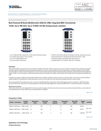
USB-1608G Series16-Bit High-Speed Multifunction DAQ DevicesFeatures 16-bit high-speed USB devices Acquisition rates up to 500 kS/s 8 differential (DIFF) or 16 singleended (SE) analog inputs Up to 2 analog outputs 8 digital I/O Two 32-bit counter inputsUSB-1608G Series provides eight differential or 16 single-ended analog inputs,two analog outputs (USB-1608GX-2AO), 8 digital I/O, and one counter input. One timer output OEM version availableOverviewSupported Operating SystemsUSB-1608G Series devices are low-cost, high-speed, analog and digital I/O USBdevices. All of these devices offer up to eight DIFF or 16 SE analog inputs, eightdigital I/O channels, two counter inputs, and one timer output. Windows 10/8/7/Vista XP32/64-bit Linux The USB-1608GX-2AO standard and OEM version offers two, 16-bit analog outputchannels with DAC rates up to 500 kS/s.Analog Input Android Retrigger ModeUSB-1608G Series devices provide 16-bitanalog inputs that are software-selectableas eight DIFF or 16 SE inputs. These devicesalso support input ranges of 10 V, 5 V, 2 V, and 1 V that are software-selectableper channel.Users can set up repetitive analog inputtrigger events. The trigger is automatically re-armed after it is activated. TheA/D trigger count (the number of samplesyou want per trigger) is configurable withsoftware.Analog Output(USB-1608GX-2AO only)Digital I/OThe USB-1608GX-2AO standard/OEMboard has two 16-bit analog outputs thatcan be updated at a rate of 250 kS/s perchannel; one output can be updated ata rate of 500 kS/s. The output range isfixed at 10 V.Trigger InputUSB-1608G Series devices have an external digital trigger input. The triggermode is software-selectable for edge- orlevel-sensitive mode. You can configureedge-sensitive mode for either rising orfalling edge. In level-sensitive mode, youcan configure for either high or low level.The default setting at power up is edgesensitive, rising edge.Eight bidirectional digital I/O lines areindividually configurable for input oroutput. The DIO terminals can detect thestate of any TTL-level input. Users canconfigure for pull-up ( 5 V) or pull-down(0 V) with an onboard jumper.Counter InputTwo 32-bit event counters are providedto count TTL pulses. The counters acceptinputs of up to 20 MHz.Timer OutputThe PWM timer output generates a pulseoutput with a programmable frequencyin the range of 0.0149 Hz to 32 MHz. Thetimer output parameters are softwareselectable.USB-1608G Series Selection ChartModelAnalogInputsSampleRate (max)AnalogOutputsSignalI/OUSB Cableand SW CDUSB-1608G16 SE/8 DIFF250 kS/s0ScrewTerminal USB-1608GX16 SE/8 DIFF500 kS/s0ScrewTerminal USB-1608GX-2AO16 SE/8 DIFF500 kS/s2ScrewTerminal USB-1608G-OEM16 SE/8 DIFF250 kS/s0Header–USB-1608GX-OEM16 SE/8 DIFF500 kS/s0Header–USB-1608GX-2AO-OEM16 SE/8 DIFF500 kS/s2Header–1
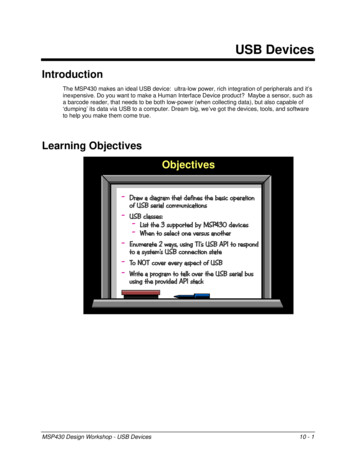
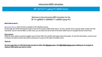
USB-1608G SeriesOverviewUSB-1608G Series Block 1608GX-2AO standard/OEM werSuppliesFPGASPIBitwiseProgrammableDIOVBUS(5 V) 16.5 V- 16.5 V1.2 V3.3 V5VSPIUSBD /D–FIFO DataClockBus BusTriggerA/D Clock InA/D Clock OutCounter In 0Counter In 1Timer OutSignal I/O ConnectorSignal I/O ConnectorAIAID/A Clock InD/A Clock OutUSB-1608GX-2AOstandard/OEMonlyMicrocontroller withHigh-SpeedUSB 2.0Compliant Interface3.3 VAlways OnENABLEsEEPROMClock OutputCrystalOscillatorUSB-1608G Series OEM VersionsThe AI clock pin outputs the signal from the internal clock.OEM versions have board-only form factors with header connectors for OEM and embedded applications (no case, CD, orUSB cable included). All devices can be further customized tomeet customer needs.CalibrationThe USB-1608G Series is factory-calibrated using a NIST-traceablecalibration process. Specifications are guaranteed for one year.The USB-1608G Series also supports field calibration for usersto calibrate the device locally with the InstaCal utility.The OEM versions have the same specifications as the standarddevices, but come in a board-only form factor with header connectorsinstead of screw terminals.2
USB-1608G SeriesSoftwareSoftware SupportUSB-1608G Series devices are supported by the software in the table below.Ready-to-Run ApplicationsDAQami InstaCal TracerDAQ andTracerDAQ ProData acquisition companion software with drag-and-drop interface that is used to acquire,view, and log data, and generate signals. DAQami can be configured to log analog, digital, andcounter channels, and to view that data in real-time or post-acquisition on user-configurabledisplays. Logged data can be exported for use in Excel or MATLAB . Windows OSDAQami is included with the free MCC DAQ Software bundle. Install DAQami and try thefully-functional software for 30 days. After 30 days, all features except for data logging and dataexport will continue to be available – data logging and data export features can be unlocked bypurchasing the software.An interactive installation, configuration, and test utility for MCC hardware. Windows OSInstaCal is included with the free MCC DAQ Software bundle.Virtual strip chart, oscilloscope, function generator, and rate generator applications used togenerate, acquire, analyze, display, and export data. Supported features may vary by hardware.The Pro version provides enhanced features. Windows OSTracerDAQ is included with the free MCC DAQ Software bundle.TracerDAQ Pro is available as a purchased software download.General-Purpose Programming SupportUniversal Library (UL) for WindowsLibrary for developing applications in C, C , VB, C# .Net, VB .Net, and Python on Windows.The UL for Windows is included with the free MCC DAQ Software bundle.The UL Python API for Windows is available on GitHub (https://github.com/mccdaq/mcculw).Library for developing applications in C, C , and Python on Linux.UL for Linux UL for Linux is available on GitHub (https://github.com/mccdaq/uldaq).Open-source, third-party Linux drivers are also available for supported MCC devices.UL for Android Library of Java classes for programmers who develop apps for Android-based mobile devices.UL for Android communicates with select MCC DAQ devices. Supports Android project development on Windows, Linux, Mac OS X.UL for Android is included with the free MCC DAQ Software bundle.Application-Specific Programming SupportULx forNI LabVIEW DASYLab MATLAB driver A comprehensive library of VIs and example programs for NI LabVIEW that is used to developcustom applications that interact with most MCC devices. Windows OSULx for NI LabVIEW is included with the free MCC DAQ Software bundle.Icon-based data acquisition, graphics, control, and analysis software that allows users to createcomplex applications in minimal time without text-based programming. Windows OSDASYLab is available as a purchased software download. An evaluation version is available for28 days.High-level language and interactive environment for numerical computation,visualization, and programming. The Mathworks Data Acquisition Toolbox allows users toacquire data from most MCC PCI and USB devices.Visit www.MathWorks.com for more information about the Data Acquisition Toolbox.3
USB-1608G SeriesSpecificationsSpecificationsCommon mode rejection ratiofIN 60 Hz, all input ranges: 86 dBCrosstalkAdjacent differential mode channels, DC to 100 kHz: –75 dBInput coupling: DCSampling rate (software-selectable)USB-1608G: 0.0149 Hz to 250 kHzUSB-1608GX/1608GX-2AO: 0.0149 Hz to 500 kHzTrigger source: TRIG (refer to “External Trigger” on page 5)Sample clock source: Internal A/D clock or external A/D clock (AICKI terminal)Burst mode: Software-selectable using the internal A/D clock; always enabledwhen using the external clock (AICKI terminal)USB-1608G: 4 µsUSB-1608GX/1608GX-2AO: 2 µsThroughputSoftware paced: 33 to 4000 S/s typ, system dependentHardware pacedUSB-1608G: 250 kS/s maxUSB-1608GX/1608GX-2AO: 500 kS/s maxChannel gain queue: Up to 16 elements; software-selectable range for each channelWarm-up time:15 minutes minThese specifications apply to both standard and OEM versions unless noted.Analog InputA/D converter type: Successive approximationADC resolution: 16 bitsNumber of channels: 8 DIFF, 16 SE; software-selectableInput voltage range: 10 V, 5 V, 2 V, 1 V; software-selectable per channelAbsolute maximum input voltageCHx relative to AGND: 25 V max (power on); 15 V max (power off)Input Impedance: 1 GΩ (power on); 820 Ω (power off)Input bias current: 10 nAInput bandwidth, all input ranges, small signal (–3 dB)USB-1608G: 750 kHzUSB-1608GX/1608GX-2AO: 870 kHzInput capacitance: 60 pfMaximum working voltage (signal common mode) 10 V range: 10.2 V max relative to AGND 5 V range: 10.2 V max relative to AGND 2 V range: 9.5 V max relative to AGND 1 V range: 9.0 V max relative to AGNDAnalog Input DC Voltage MeasurementAll Values are ( )RangeGain Error(% of Reading)Offset Error(µV)INL Error(% of Range)Absolute Accuracyat Full Scale(µV)Gain TemperatureCoefficient(% reading/ C)Offset TemperatureCoefficient(µV/ C) 10 V0.0249150.007640750.001447 5 V0.0246860.007622660.001424 2 V0.0243360.00769680.001410 1 V0.0242450.00765610.00145** Settling time is defined as the expected accuracy after one conversion whenswitching from a channel with a DC input at one extreme of full scale to anotherchannel with a DC input at the other extreme of full scale. Both input channelsare configured for the same input range.Noise Performance*Range 10 V 5 V 2 V 1 VCounts6679LSBrms0.910.911.061.36Analog Output (USB-1608GX-2AO only)Number of channels: 2 (leave unused AOUTx output channels disconnected)Resolution: 16 bitsOutput range: 10 V (calibrated)Output transientHost computer is reset, powered on, suspended, or a reset command isissued to the deviceDuration: 500 µsAmplitude: 2 V pk-pkPowered offDuration: 10 msAmplitude: 7 V peakDifferential non-linearity: 0.25 LSB typ; 1 LSB maxOutput currentAOUTx: 3.5 mA maxOutput short-circuit protectionAOUTx connected to AGND: Unlimited durationOutput coupling: DCPower on and reset stateDACs cleared to zero-scale: 0 V, 50 mV (AOUTx defaults to 0 V when the hostis reset, powered on, suspended, or a reset command is issued to the device)Output noise: 30 µVrmsTrigger source: TRIG (refer to “External Trigger” on page 5)Sample clock source: Internal D/A clock or external D/A clock (AOCKI terminal)Output update rate: 500 kHz/number of channels in the scanSettling TimeTo rated accuracy, 10 V step: 40 µsSlew rate: 9 V/µsThroughputSoftware paced: 33 S/s to 4000 S/s typ, system-dependentHardware paced: 500 kS/s max, system-dependent* For the peak-to-peak noise distribution test, a differential input channel is connected to AGND at the input terminal block, and 32,000 samples are acquired atthe maximum rate available at each setting.Settling Time**USB-1608GRange 10 V 5 V 2 V 1 VRange 10 V 5 V 2 V 1 V4 µS settlingaccuracy(% FSR)6 µS settlingaccuracy(% 31USB-1608GX/1608GX-2AO2 µS settlingaccuracy(% FSR)0.12510.06870.06870.06874 µS settlingaccuracy(% FSR)0.00310.00310.00310.003110 µS settling accuracy(% FSR)0.00150.00150.00150.00159 µS settlingaccuracy(% FSR)0.00150.00150.00150.00154
USB-1608G SeriesSpecificationsInput type: Schmitt trigger, 33 Ω series resistor, 47 kΩ pull-down to groundSchmitt trigger hysteresis: 0.4 V to 1.2 VInput high voltage: 2.2 V min, 5.5 V absolute maxInput low voltage: 1.5 V max, –0.5 V absolute min, 0 V recommended minOutput high voltage: 4.4 V min (IOH –50 µA), 3.76 V min (IOH –2.5 mA)Output low voltage: 0.1 V max (IOL 50 µA), 0.44 V max (IOL 2.5 mA)Output current: 2.5 mA maxCalibrated Absolute AccuracyRange: 10 VAbsolute accuracy ( LSB): 16.0Calibrated Absolute Accuracy ComponentsRange: 10 V% of reading: 0.0183Offset ( mV): 1.831Offset Tempco (µV/ C): 12.7Gain Tempco (ppm of range/ C): 13Counter InputTerminal names: CTR0, CTR1Number of channels: 2 channelsResolution: 32-bitCounter type: Event counterInput type: Schmitt trigger, 33 Ω series resistor, 47 kΩ pull-down to groundInput source:CTR0 (terminal 52)CTR1 (terminal 51)Counter read/Writes rates (Software-paced) : 33 to 8000 reads/writes per secondtyp, system dependentInput high voltage: 2.2 V min, 5.5 V maxInput low voltage: 1.5 V max, –0.5 V minSchmitt trigger hysteresis: 0.4 V min, 1.2 V maxInput frequency: 20 MHz, maxHigh pulse width: 25 ns, minLow pulse width: 25 ns, minAnalog Output Relative AccuracyRange: 10 VRelative accuracy (INL): 4.0 typAnalog Input/Output CalibrationRecommended Warm-up Time: 15 minutes minCalibration method: Self-calibration (firmware)Calibration interval: 1 year (factory calibration)AI calibration reference 5 V, 2.5 mV max (actual measured values stored in EEPROM)Tempco: 5 ppm/ C maxLong term stability: 15 ppm/1000 hoursAOUTx calibration procedure (USB-1608GX-2AO only)The AOUTx terminals are internally routed to the AI circuit. For best results,disconnect AOUTx connections at the terminal block before calibrating.Timer OutputDigital I/OTimer terminal name: TMRTimer type: PWM output with count, period, delay, and pulse width registersOutput value: Idle low with pulses high, software-selectable output invertInternal clock frequency: 64 MHzRegister widths: 32-bitHigh pulse width: 15.625 ns minLow pulse width: 15.625 ns minOutput high voltage: 4.4 V min (IOH –50 µA), 3.76 V min (IOH –2.5 mA)Output low voltage: 0.1 V max (IOL 50 µA), 0.44 V max (IOL 2.5 mA)Output Current: 2.5 mA maxDigital type: CMOSNumber of I/O: 8Configuration: Bit-configurable as input (power on default) or outputPull-up configuration: 47 kΩ resistors configurable as pull-up/down (default)via internal jumper (W1).Digital I/O transfer rate (system-paced): 33 to 8000 port reads/writes or singlebit reads/writes per second typ, system dependent.Input high voltage: 2.0 V min, 5.5 V absolute maxInput low voltage: 0.8 V max, –0.5 V absolute min, 0 V recommended minOutput high voltage: 4.4 V min (IOH –50 µA), 3.76 V min (IOH –2.5 mA)Output low voltage: 0.1 V max (IOL 50 µA), 0.44 V max (IOL 2.5 mA)Output current: 2.5 mA maxMemoryData FIFO:USB-1608G/1608GX: 4 kS analog inputUSB-1608GX-2AO: 4 kS analog input, 2 kS analog outputNon-volatile memory: 32 KB (28 KB firmware storage, 4 KB calibration/user data)External TriggerTrigger source: TRIG inputTrigger mode: Software configurable for edge or level sensitive, rising or fallingedge, high or low level. Power on default is edge sensitive, rising edge.Trigger latency: 1 µs 1 clock cycle maxTrigger pulse width: 100 ns minInput type: Schmitt trigger, 33 Ω series resistor and 49.9 kΩ pull-down to groundSchmitt trigger hysteresis: 0.4 V to 1.2 VInput high voltage: 2.2 V min, 5.5 V absolute maxInput low voltage: 1.5 V max, –0.5 V absolute min, 0 V recommended minPowerSupply currentThe total quiescent current requirement includes up to 10 mA for the Status LED; this does not include any potential loading of the digital I/O bits, 5 V terminal, or the AOUTx outputs (USB-1608GX-2AO only).Quiescent CurrentUSB-1608G/1608GX: 230 mAUSB-1608GX-2AO: 260 mA 5 V user output voltage range (available at Terminal 43): 4.5 V min to 5.25 V max 5 V user output current (available at terminal 43): 10 mA maxExternal Clock I/OTerminal namesAICKI, AICKOUSB-1608GX-2AO: AICKI, AICKO AOCKI, AOCKOTerminal typesAxCKI: Input, active on rising edgeAxCKO: Output, power on default is 0 V, active on rising edgeTerminal descriptionsAxCKI: Receives sampling clock from external sourceAxCKO: Outputs the internal sampling clock (D/A or A/D clock) or the pulsegenerated from AxCKI when in external clock mode.Input clock rateUSB-1608G: 250 kHz maxUSB-1608GX/1608GX-2AO: 500 kHz maxClock pulse widthAxCKI: 400 ns minAxCKO: 400 ns minEnvironmentalOperating temperature range: 0 C to 55 C maxStorage temperature range: –40 C to 85 C maxHumidity: 0% to 90% non-condensing maxMechanicalSignal I/O connector-OEM models: Two 28-pin, 0.1 in. pitch headersAll other devices: 2 banks of screw-terminal blocks (wire gauge range16 AWG to 30 AWG)Dimensions (L W H):Standard version: 127 89.9 35.6 mm (5.00 3.53 1.40 in.)OEM version: 121.92 86.36 15.24 (4.80 3.40 0.60 in.)5
USB-1608G SeriesOrderingOrder InformationHardwareSoftware also Available from MCCDAQamiEasy-to-use advanced data logging software toacquire, view, and log dataPart No.DescriptionTracerDAQ ProUSB-1608G16-channel, 250 kS/s sampling DAQ device withtwo 32-bit counter inputs, one timer output, andeight digital I/O lines. Includes a USB cable andMCC DAQ software.Out-of-the-box virtual instrument suite with stripchart, oscilloscope, function generator, and rategenerator – professional versionDASYLabIcon-based data acquisition, graphics, control,and analysis softwareUSB-1608GX16-channel, 500 kS/s sampling DAQ device withtwo 32-bit counter inputs, one timer output, andeight digital I/O lines. Includes a USB cable andMCC DAQ software.USB-1608GX-2AO16-channel, 500 kS/s sampling DAQ device withtwo analog outputs, two 32-bit counter inputs,one timer output, and eight digital I/O lines.Includes a USB cable and MCC DAQ software.USB-1608G-OEMBoard-only DAQ device with 16-channels,250 kS/s sampling, two 32-bit counter inputs,one timer output, and eight digital I/O lines.USB-1608GX-OEMBoard-only DAQ device with 16-channels,500 kS/s sampling, two 32-bit counter inputs,one timer output, and eight digital I/O lines.USB-1608GX-2AO-OEMBoard-only DAQ device with 16-channels,500 kS/s sampling, two analog outputs, two32-bit counter inputs, one timer output, andeight digital I/O lines.
NI LabVIEW A comprehensive library of VIs and example programs for NI LabVIEW that is used to develop custom applications that interact with most MCC devices. Win dows OS ULx for NI LabVIEW is included with the free MCC DAQ Software bundle. DASYLab Icon-based data acquisition, graphics, control, and analysis software that allows users to .