Transcription
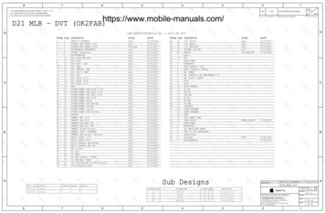
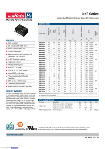
NKE Serieswww.murata-ps.comIsolated Sub-Miniature 1W Single Output DC-DC ConvertersSub-miniature SIP & DIP styles 3kVDC isolation ‘Hi Pot Test’ UL60950 recognised Wide temperature performance at full 1 Watt load, –40 C to 85 CUL 94V-0 package material Footprint at 0.69cm 2Industry standard pinout 3.3V, 5V & 12V inputs 3.3V, 5V, 9V, 12V & 15V outputs Internal SMD construction Fully encapsulated with toroidal magneticsMTTF up to 2.4 million hours Custom solutions available No electrolytic or tantalum capacitors PRODUCT OVERVIEWThe NKE sub-miniature series of DC-DC Convertersis particularly suited to isolating and/or convertingDC power rails. A smaller package size, improvedefficiency, lower output ripple and 3kVDC isolationcapability through state of the art packaging andimproved technology. The galvanic isolation allowsthe device to be configured to provide an isolatednegative rail in systems where only positive railsexist. The wide temperature range guaranteesstartup from –40 C and full 1 watt output at 85 C.For full details go 550576035505760MIL.Tel.kHrs4337 46,9694105 46,7831904 28,9184337 46,9694105 46,7831904 28,9183710 36,2344277 34,8972686 35,9193729 76,5532910 73,5232211 71,7253710 36,2344277 34,8972686 35,9193729 76,5532910 73,5232211 71,7253981 58,2023482 57,8951982 77,8062122 56,4043981 58,2023482 57,8951982 77,8062122 56,404PackageStylemAMTTF1VIsolation CapacitanceVEfficiencyInputCurrent at Rated LoadRoHS compliant Output CurrentFEATURESOutputVoltageOrder CodeNominal InputVoltageSELECTION GUIDEDIPSIPDIPSIPDIPSIPNKE0505SEC/NKE0505DEC offers higher efficiency than NKE0505SC/NKE0505DC but over a narrower operating temperature range.See temperature characteristics graph.INPUT CHARACTERISTICSParameterVoltage rangeReflected ripple currentConditionsMin.Typ.Max.Continuous operation, 3.3V input typesContinuous operation, 5V input typesContinuous operation, 12V input types3.3V input types2.974.510.83.35.012.0403.635.513.260UnitsVmA p-p1.Calculated using MIL-HDBK-217 FN2 and Telcordia SR-332 calculation model with nominal input voltage at full load.All specifications typical at TA 25 C, nominal input voltage and rated output current unless otherwise specified.www.murata.comKDC NKE.L01 Page 1 of 9Downloaded from Arrow.com.
NKE SeriesIsolated Sub-Miniature 1W Single Output DC-DC ConvertersOUTPUT CHARACTERISTICSParameterConditionsRated PowerVoltage Set Point AccuracyLine regulationTA -40 C to 120 C, see derating graphsSee tolerance envelopeHigh VIN to low VIN10% load to rated load, 3.3V output types & 030910% load to rated load, 5V output types10% load to rated load, 9V output types10% load to rated load, 12V output types10% load to rated load, 15V output typesBW DC to 20MHz, 3.3V output types & 0305, 0505SEC, 0505DECBW DC to 20MHz, other 5V output typesBW DC to 20MHz, 9V output typesBW DC to 20MHz, 12V output typesBW DC to 20MHz, 15V output typesLoad Regulation1Ripple and 321.21515109.58.580100906555%/%Typ.Max.%mV p-pISOLATION CHARACTERISTICSParameterConditionsMin.Isolation test voltageResistanceFlash tested for 1 secondViso 1000VDC3000ParameterConditionsMin.Switching frequencyAll output typesUnitsVDCGΩ10GENERAL CHARACTERISTICSTyp.Max.115UnitskHzTEMPERATURE onStorageAll output types, See safety approval section for UL temperature specification1-40-50Case temperature rise aboveambientCooling0505D/S, 1205D/SAll other output typesFree air convectionTyp.Max.Units851304132 CABSOLUTE MAXIMUM RATINGSLead temperature 1.5mm from case for 10 secondsWave SolderInput voltage VIN, NKE03 typesInput voltage VIN, NKE05 typesInput voltage VIN, NKE12 types260 CWave Solder profile not to exceed the profile recommended in IEC 61760-1Section 6.1.3. Please refer to application notes for further information.5.5V7V15V1. 12V input types have typically 3% less load regulation.www.murata.comKDC NKE.L01 Page 2 of 9Downloaded from Arrow.com.
NKE SeriesIsolated Sub-Miniature 1W Single Output DC-DC ConvertersTECHNICAL NOTESISOLATION VOLTAGE‘Hi Pot Test’, ‘Flash Tested’, ‘Withstand Voltage’, ‘Proof Voltage’, ‘Dielectric Withstand Voltage’ & ‘Isolation Test Voltage’ are all terms that relate to the same thing, a test voltage,applied for a specified time, across a component designed to provide electrical isolation, to verify the integrity of that isolation.Murata Power Solutions NKE series of DC-DC converters are all 100% production tested at their stated isolation voltage. This is 3000V DC for 1 second.A question commonly asked is, “What is the continuous voltage that can be applied across the part in normal operation?”The NKE series has been recognised by Underwriters Laboratory for functional insulation. Both input and output should normally be maintained within SELV limits i.e. less than42.4V peak, or 60VDC. The isolation test voltage represents a measure of immunity to transient voltages and the part should never be used as an element of a safety isolation system. The part could be expected to function correctly with several hundred volts offset applied continuously across the isolation barrier; but then the circuitry on both sides of thebarrier must be regarded as operating at an unsafe voltage and further isolation/insulation systems must form a barrier between these circuits and any user-accessible circuitryaccording to safety standard requirements.REPEATED HIGH-VOLTAGE ISOLATION TESTINGIt is well known that repeated high-voltage isolation testing of a barrier component can actually degrade isolation capability, to a lesser or greater degree depending on materials, construction and environment. While manufactured parts can withstand several times the stated test voltage, the isolation capability does depend on the wire insulation. Anymaterial, including this enamel (typically polyurethane) is susceptible to eventual chemical degradation when subject to very high applied voltages thus implying that the number oftests should be strictly limited. We therefore strongly advise against repeated high voltage isolation testing, but if it is absolutely required, that the voltage be reduced by 20% fromspecified test voltage.RoHS COMPLIANCE INFORMATIONThis series is compatible with RoHS soldering systems with a peak wave solder temperature of 260 C for 10 seconds. Please refer toapplication notes for further information. The pin termination finish on the SIP package type is Tin Plate, Hot Dipped over Matte Tin with NickelPreplate. The DIP types are Matte Tin over Nickel Preplate. Both types in this series are backward compatible with Sn/Pb soldering systems.For further information, please visit www.murata-ps.com/rohsSAFETY APPROVALThe NKE series has been recognised by Underwriters Laboratory (UL) to UL 60950 for functional insulation in a maximum ambient temperature of 85ºC and/or case temperaturelimit of 130ºC. Case temperature measured on the face opposite the pins. File number E151252 applies.PART NUMBER STRUCTURENKE XX XX X CSeries nameRoHS compliantInput voltagePackage typeOutput voltageS - SIPD - DIPM - Surface mountZ - ZIPwww.murata.comKDC NKE.L01 Page 3 of 9Downloaded from Arrow.com.
NKE SeriesIsolated Sub-Miniature 1W Single Output DC-DC ConvertersCHARACTERISATION TEST METHODSRipple & Noise Characterisation MethodRipple and noise measurements are performed with the following test configuration.C11μF X7R multilayer ceramic capacitor, voltage rating to be a minimum of 3 times the output voltage of the DC-DC converter10μF tantalum capacitor, voltage rating to be a minimum of 1.5 times the output voltage of the DC-DC converter with an ESR of lessthan 100mΩ at 100 kHzC3100nF multilayer ceramic capacitor, general purposeR1450Ω resistor, carbon film, 1% toleranceR250Ω BNC terminationT13T of the coax cable through a ferrite toroidRLOADResistive load to the maximum power rating of the DC-DC converter. Connections should be made via twisted wiresMeasured values are multiplied by 10 to obtain the specified values.C2Differential Mode Noise Test SchematicDC/DC ConverterOSCILLOSCOPEC1 C2 C3 SUPPLYInput- R1T1R2Y INPUTOutput-R LOADAPPLICATION NOTESMinimum loadThe minimum load to meet datasheet specification is 10% of the full rated load across the specified input voltage range. Lower than 10% minimum loading will result inan increase in output voltage, which may rise to typically double the specified output voltage if the output load falls to less than 5%.Capacitive loading and start upTypical start up times for this series, with a typical input voltage rise time of 2.2μs and output capacitance of 10μF, are shown in the table below. The productseries will start into a capacitance of 47μF with an increased start time, however, the maximum recommended output capacitance is 10μF.Typical Start-Up Wave KE0505SECNKE0509SCStart-up NKE1205SCNKE1209SCNKE1212SCNKE1215SCStart-up timeμs504099401671283552958475www.murata.comKDC NKE.L01 Page 4 of 9Downloaded from Arrow.com.
NKE SeriesIsolated Sub-Miniature 1W Single Output DC-DC ConvertersAPPLICATION NOTES (Continued)Output Ripple ReductionBy using the values of inductance and capacitance stated, the output ripple at the rated load is lowered to 5mV p-p max.Component selectionCapacitor: It is required that the ESR (Equivalent Series Resistance) should be as low as possible, ceramic types are recommended.The voltage rating should be at least twice (except for 15V output), the rated output voltage of the DC-DC converter.Inductor: The rated current of the inductor should not be less than that of the output of the DC-DC converter. At the rated current, the DC resistance of the inductorshould be such that the voltage drop across the inductor is 2% of the rated voltage of the DC-DC converter. The SRF (Self Resonant Frequency) should be xCNKE1205xCNKE1209xCNKE1212xCNKE1215xCL, 3C82473C82683C82104CCLoadDCThrough itorC, 2μF4.7μF1μF0.47μF2.2μFwww.murata.comKDC NKE.L01 Page 5 of 9Downloaded from Arrow.com.
NKE SeriesIsolated Sub-Miniature 1W Single Output DC-DC ConvertersTOLERANCE ENVELOPESThe voltage tolerance envelope shows typical load regulation characteristics for this product series. The tolerance envelope is the maximum output voltage variation due tochanges in output loading.3.3V OUTPUT TYPESALL OTHER TYPESTypical Load9%Line1%1%-7%-7%Output VoltageOutput Voltage10%Typical5%Load Line2.5%-2.5%0%-7.5%-15%102550751001025Output Load Current (%)5075100Output Load Current (%)TEMPERATURE DERATING GRAPHS1.00.50-401.5All other types.Output Power (W)UL recognition to amaximum ambienttemperature of 85ºC and/or case temperature limit of130ºC.1.5Output Power (W)NKE 0303DC/SC, 0305DC/SC, 0309DC/SC, 0503DC/SC,0505DEC/SEC types only.85 CSafe Operating Area100500Ambient Temperature ( C)1501.00.585 CSafe Operating Area120 C0-40100500Ambient Temperature ( C)150www.murata.comKDC NKE.L01 Page 6 of 9Downloaded from Arrow.com.
NKE SeriesIsolated Sub-Miniature 1W Single Output DC-DC ConvertersPACKAGE SPECIFICATIONSMECHANICAL DIMENSIONSPIN CONNECTIONS - 8 PIN DIPDIP PackageSIP PackagePinXXXXFunction1-VIN4 VIN5 VOUT7-VOUTPIN CONNECTIONS - 4 PIN SIP11.53 0.2 [0.454 0.008]0.40 [0.016] MINPinNKEXXXXSC7.46 0.25 [0.294 0.010]XYYWW14.10 0.5 [0.161 0.020]2.54 [0.100](1.95 [0.077])(1.13 [0.044])23S4Function1-VIN2 VIN3-VOUT4 VOUT0.50 0.05 [0.020 0.002]0.25 0.05 [0.010 0.002]6.10 0.15-0.25-0.010 ][0.240 0.006All dimensions in mm (inches) Controlling dimension is mm.All pins on a 2.54 (0.100) pitch and within 0.1 (0.004) of true position from pin 1 at seating plane ‘S’Weight: 1.09g (SIP) 1.25g (DIP)www.murata.comKDC NKE.L01 Page 7 of 9Downloaded from Arrow.com.
NKE SeriesIsolated Sub-Miniature 1W Single Output DC-DC ConvertersPACKAGE SPECIFICATIONS (Continued)RECOMMENDED FOOTPRINT DETAILS8 Pin DIP Package4 Pin SIP Package2.54 [0.100]x4 HOLESØ 0.0450.039Ø 1.151.00[]2.54 [0.100]TUBE OUTLINE DIMENSIONS4 Pin SIP Tube8 Pin DIP Tube12.60 (0.496)11.60 (0.457)7.7 [0.303]9.3 [0.366]14.8 [0.583]5.40 (0.213)5.00 (0.197)0.60 0.15 (0.0236 0.006)Unless otherwise specified all dimensions in mm [inches] 0.55mm [0.022].Tube length (8 Pin DIP) : 520mm 2mm (20.47).Tube length (4 Pin SIP) : 525mm 2mm (20.67).4.45 [0.175]Tube Quantity : 40www.murata.comKDC NKE.L01 Page 8 of 9Downloaded from Arrow.com.
NKE SeriesIsolated Sub-Miniature 1W Single Output DC-DC ConvertersDISCLAIMERUnless otherwise stated in the datasheet, all products are designed for standard commercial and industrial applications and NOT for safety-critical and/or life-criticalapplications.Particularly for safety-critical and/or life-critical applications, i.e. applications that may directly endanger or cause the loss of life, inflict bodily harm and/or loss or severedamage to equipment/property, and severely harm the environment, a prior explicit written approval from Murata is strictly required. Any use of Murata standard products for any safety-critical, life-critical or any related applications without any prior explicit written approval from Murata shall be deemed unauthorised use.These applications include but are not limited to: Aircraft equipment Aerospace equipment Undersea equipment Power plant control equipment Medical equipment Transportation equipment ( automobiles, trains, ships, etc.) Traffic signal equipment Disaster prevention / crime prevention equipment Data Processing equipmentMurata makes no express or implied warranty, representation, or guarantee of suitability, fitness for any particular use/purpose and/or compatibility with any application or device of the buyer, nor does Murata assume any liability whatsoever arising out of unauthorised use of any Murata product for the application of the buyer. Thesuitability, fitness for any particular use/purpose and/or compatibility of Murata product with any application or device of the buyer remain to be the responsibility andliability of the buyer.Buyer represents and agrees that it has all the necessary expertise to create and implement safeguards that anticipate dangerous consequences of failures, monitor failures and their consequences, lessen the likelihood of failures that might cause harm, and take appropriate remedial actions. Buyer will fully indemnify and holdMurata, its affiliated companies, and its representatives harmless against any damages arising out of unauthorised use of any Murata products in any safety-critical and/or life-critical applications.Remark: Murata in this section refers to Murata Manufacturing Company and its affiliated companies worldwide including, but not limited to, Murata Power Solutions.This product is subject to the following operating requirementsand the Life and Safety Critical Application Sales Policy:Refer to: ementsMurata Power Solutions (Milton Keynes) Ltd. makes no representation that the use of its products in the circuits described herein, or the useof other technical information contained herein, will not infringe upon existing or future patent rights. The descriptions contained herein donot imply the granting of licenses to make, use, or sell equipment constructed in accordance therewith. Specifications are subject to changewithout notice. 2021 Murata Power Solutions (Milton Keynes) Ltd.www.murata.comKDC NKE.L01 Page 9 of 9Downloaded from Arrow.com.
ISOLATION VOLTAGE Hi Pot Test , Flash Tested , Withstand Voltage , Proof Voltage , Dielectric Withstand Voltage & Isolation Test Voltage are all terms that relate to the same thing, a test voltage, applied for a speci ed time, across a component designed to provide electrical isolation, to verify the integrity of that isolation.
![CHIP FERRITE BEAD BLM15 Murata Standard Reference Specification [AEC-Q200]](/img/53/qnfa9103.jpg)