Transcription
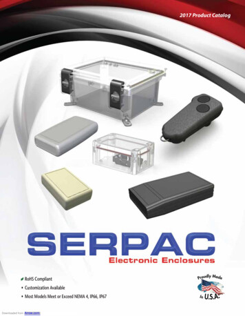
MEJ1 Serieswww.murata-ps.com5.2kVDC Isolated 1W DC-DC 5512121524243.353.35912153.3591215591215591215 3.3 5 9 12 9 12 15 9 8366 151 100 55 42 55 42 33 55 349234852908291124403208269751212121515152424 15 3.3 5 15 5 9 12 5 12 33 151 100 33 100 55 42 100 rnativeEfficiency (Typ)Efficiency (Min)Ripple & Noise (Max)3Ripple & Noise (Typ)3Load Regulation (Max)Load Regulation (Typ)Output VoltageOutput CurrentNominal InputVoltageOrder CodeInput Current (Typ)SELECTION GUIDEkHrsFEATURES Basic/supplementary isolation toUL609502 ANSI/AAMI ES60601-1 Single and dual outputs UL 94V-0 package material 5.2kVDC isolation ‘Hi Pot Test’ 3.3V, 5V, 12V, 15V & 24V inputsSingle SIP package style 3.3V, 5V, 9V, 12V & 15V outputs Internal SMD construction Fully encapsulated with toroidal magnetics Pin compatible with the MEV, NMV, NMK,MEJ2 & NMJ series Continuous barrier withstand voltage2.4kVDCDual Characterised CMTI 200kV/μSPRODUCT OVERVIEWDualThe MEJ1 series are single and dual output DC-DCconverters in a 7 pin SIP package style offering anisolation and insulation upgrade path from the NMV& MEV1 series’. The MEJ1 series has UL60950and ANSI/AAMI ES60601-1 recognition, whichmakes it ideal for applications where safety andminiaturisation are of paramount importance.For full details go J1D1509SCMEJ1D1512SCMEJ1D2405SCMEJ1D2412SCContact 1. Calculated using MIL-HDBK-217 FN2 calculation model with nominal input voltage at full load.2. See safety approvals section for limitations of use.3. See ripple & noise test method.All specifications typical at TA 25 C, nominal input voltage and rated output current unless otherwise specified.www.murata.comKDC MEJ1 I01 Page 1 of 11Downloaded from Arrow.com.
MEJ1 Series5.2kVDC Isolated 1W DC-DC ConvertersINPUT CHARACTERISTICSParameterVoltage rangeInput reflected rippleConditionsMin.Typ.Max.UnitsContinuous operation, 3V input typesContinuous operation, 5V input typesContinuous operation, 12V input typesContinuous operation, 15V input typesContinuous operation, 24V input types3.3V input types5V input types12V & 15V input types24V input .216.526.4VmAOUTPUT CHARACTERISTICSParameterConditionsTA -40ºC to 85ºCRated Power2Voltage Set Point AccuracySee tolerance envelopesLine regulationHigh VIN to low ION CHARACTERISTICSParameterIsolation test voltageResistanceIsolation capacitanceContinuous barrier withstand voltageUL60950-1Safety standard ANSI/AAMIES60601-1ConditionsMin.Production tested for 1 secondQualification tested for 1 secondQualification tested for 1 minuteViso 500VDC520070005200VDC13Non-safety barrier applicationBasic/supplementary24002001 MOOP200GΩpFVVrmsGENERAL CHARACTERISTICSParameterConditionsSwitching frequencyAll typesMin.Typ.Max.50UnitskHzTEMPERATURE onStorageAll output types, (see safety approval section for limitations)-40-55Case Temperature above ambientCoolingMEJ1S1212SC, MEJ1S1512SC, MEJ1S2412SC, MEJ1D1215SC, MEJ1D1512SC,MEJ1D2412SC, MEJ1D2415SC, MEJ1S1215SC, MEJ1S1509SC, MEJ1S2409SCMEJ1D1205SC, MEJ1D1209SC, MEJ1D2405SC, MEJ1D2409SC, MEJ1S1209SC,MEJ1S1515SC, MEJ1S2415SC, MEJ1D1212SC, MEJ1D1509SC, MEJ1S0515SC,MEJ1S2405SC, MEJ1D0512SC, MEJ1D0515SC, MEJ1D1515SC, MEJ1S1505SC ,MEJ1D0505SC, MEJ1D0509SC, MEJ1D1203SC, MEJ1D1505SC, MEJ1S0509SC,MEJ1S0512SC, MEJ1S1205SCMEJ1S0505SC, MEJ1S1203SC, MEJ1D0503SC, MEJ1S0303SC, MEJ1S0305SC,MEJ1S0503SCFree air convectionTyp.Max.Units8512513 C1721ABSOLUTE MAXIMUM RATINGSShort-circuit protectionLead temperature 1mm from case for 10 seconds48 Hours260 CWave SolderWave Solder profile not to exceed the profile recommended in IEC 61760-1Section 6.1.3. Please refer to application notes for further information.Input voltage VIN, MEJ1x03xxSCInput voltage VIN, MEJ1x05xxSCInput voltage VIN, MEJ1x12xxSCInput voltage VIN, MEJ1x15xxSCInput voltage VIN, MEJ1x24xxSC5V7V15V18V28Vwww.murata.comKDC MEJ1 I01 Page 2 of 11Downloaded from Arrow.com.
MEJ1 Series5.2kVDC Isolated 1W DC-DC ConvertersTECHNICAL NOTESISOLATION VOLTAGE‘Hi Pot Test’, ‘Flash Tested’, ‘Withstand Voltage’, ‘Proof Voltage’, ‘Dielectric Withstand Voltage’ & ‘Isolation Test Voltage’ are all terms that relate to the same thing, a testvoltage, applied for a specified time, across a component designed to provide electrical isolation, to verify the integrity of that isolation.Murata Power Solutions MEJ1 series of DC-DC converters are all 100% production tested at 5.2kVDC for 1 second and qualification tested at 7kVDC for 1 second,5.2kVDC for 1 minute.The MEJ1 series is recognised by Underwriters Laboratory, please see safety approval section for more information. When the insulation in the MEJ1 series is not usedas a safety barrier, i.e. provides functional isolation only, continuous or switched voltages across the barrier up to 2.4kV are sustainable. This is established by measuringthe partial discharge Inception voltage in accordance with IEC 60270. Please contact Murata for further information.REPEATED HIGH-VOLTAGE ISOLATION TESTINGIt is well known that repeated high-voltage isolation testing of a barrier component can actually degrade isolation capability, to a lesser or greater degree depending onmaterials, construction and environment. We therefore strongly advise against repeated high voltage isolation testing, but if it is absolutely required, that the voltage bereduced by 20% from specified test voltage.SAFETY APPROVALANSI/AAMI ES60601-1The MEJ1 series have recognised by Underwriters Laboratory (UL) to ANSI/AAMI ES60601-1 and provides 1 MOOP (Means Of Operator Protection) based upon a working voltage of200 Vrms max and 280 Vpk max., between Primary and Secondary and between Primary and its Enclosure, in a maximum ambient temperature of 85 C and/or case temperaturelimit of 130 C (case temperature measured on the face opposite the pins).File Number E202895 applies.UL60950The MEJ1 series have been recognised by Underwriters Laboratory (UL) to UL60950 for basic/supplementary insulation to a working voltage of 200Vrms in a maximum ambienttemperature of 85 C and/or case temperature limit of 130 C (case temperature measured on the face opposite the pins).File number E151252 applies.Creepage and clearance 2mmWorking altitude 4000mFUSINGThe MEJ1 Series of converters are not internally fused so to meet the requirements of UL an anti-surge input line fuse should always be used with ratings as defined below.MEJ1x03xxSC 1AMEJ1x05xxSC 1AMEJ1x12xxSC 500mAMEJ1x15xxSC 500mAMEJ1x24xxSC 200mAAll fuses should be UL recognised and rated to at least the maximum allowable DC input voltage.RoHS COMPLIANCE INFORMATIONThis series is compatible with RoHS soldering systems with a peak wave solder temperature of 260ºC for 10 seconds. Please refer to applicationnotes for further information. The pin termination finish on this product series is Tin Plate, Hot Dipped over Matte Tin with Nickel Preplate. Theseries is backward compatible with Sn/Pb soldering systems. For further information, please visit www.murata-ps.com/rohswww.murata.comKDC MEJ1 I01 Page 3 of 11Downloaded from Arrow.com.
MEJ1 Series5.2kVDC Isolated 1W DC-DC ConvertersENVIRONMENTAL VALIDATION TESTINGThe following tests have been conducted on this product series, as part of our design verification process. The datasheet characteristics specify user operating conditions for thisseries, please contact Murata if further information about the tests is required.TestStandardConditionTemperature cyclingMIL-STD-883 Method 1010, Condition B10 cycles between two chambers set to achieve -55 C and 125 C. The dwell time shall not beless than 10min.Humidity biasStorage lifeJEDEC JESD22-A101JEDEC JESD22-A103, Condition A85 C 2 C, 85% 5% R.H. for 1000 hours.125 C 10/-0 C for 1000 hours.VibrationMIL-STD-883 Method 2007, Condition A1.5mm pk-pk / 20g pk min, 20-2000Hz, 4 sweeps in each of 3 mutually perpendicular axis at 3oct/min.ShockESDBumpMIL-STD-883 Method 2002, Condition AJEDEC JESD22-A114IEC Class 4M5 ofETS 300 019-2-4500g 1.0ms half sine, 5 shocks in each direction of 3 mutually perpendicular axes.HBM Testing Standard at 3 stress levels; 2.0kV, 4.0kV and 8.0kV.Shock Spectrum Type II, 6mS duration, 250m/s2 500 bumps in 6 directions.SolderabilityIPC/ECA J-STD-002, Test A and A1SnPb (Test A) For leaded solderability the parts are conditioned in a steam ager for 8 hours 15min. at a temperature of 93 3 C. Dipped in solder at 245 C 5 C for 5 0/-0.5 seconds.Pb-free (Test A1) For lead free solderability the parts are conditioned in a steam ager for 8 hours 15 min. at a temperature of 93 3 C. Dipped in solder at 255 C 5 C for 5 0/-0.5 seconds.Solder heatJEDEC JESD22-B106The test sample is subjected to a molten solder bath at 260 5 C for 10 seconds (96SC tin/silver/copper).Solder heat (hand)MIL-STD-202 Method 210, Condition AThe soldering iron is heated to 350 C 10 C and applied to the terminations for a duration of 4to 5 seconds.Solvent cleaningSolvent ResistanceLead Integrity (Adhesion)Lead Integrity (Fatigue)Resistance to cleaning agents.MIL-STD-883 Method 2015MIL-STD-883 Method 2025MIL-STD-883 Method 2004, condition B2Solvent – Novec 71IPA & Topklean EL-20A. Pulsed ultrasonic immersion 45 C- 65 C.Separate samples subjected to solvent A, solvent B and solvent D.Leads are bent through 90º until a fracture occurs.The leads are bent to an angle of 15º. Each lead is subjected to 3 cycles.Lead Integrity (Tension/Pull)MIL-STD-883 Method 2004, Condition A1Pull of 0.227kg applied for 30 seconds. The force is then increased until the pins snap.PART NUMBER STRUCTUREMEJ 1 X XX XX S CSeries nameRoHS compliantPower ratingPackage typeOutput typeS - SIPD - DIPM - Surface mountZ - ZIPS - SingleD - DualT - TripleQ - QuadOutput voltageInput voltagewww.murata.comKDC MEJ1 I01 Page 4 of 11Downloaded from Arrow.com.
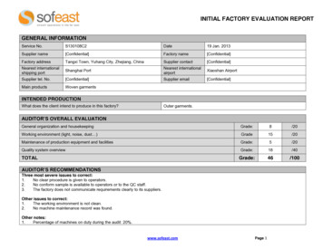
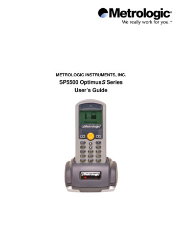
MEJ1 Series5.2kVDC Isolated 1W DC-DC ConvertersCHARACTERISATION TEST METHODSRipple & Noise Characterisation MethodRipple and noise measurements are performed with the following test configuration.C11μF X7R multilayer ceramic capacitor, voltage rating to be a minimum of 3 times the output voltage of the DC-DC converter10μF tantalum capacitor, voltage rating to be a minimum of 1.5 times the output voltage of the DC-DC converter with an ESR of lessthan 100mΩ at 100 kHzC3100nF multilayer ceramic capacitor, general purposeR1450Ω resistor, carbon film, 1% toleranceR250Ω BNC terminationT13T of the coax cable through a ferrite toroidRLOADResistive load to the maximum power rating of the DC-DC converter. Connections should be made via twisted wiresMeasured values are multiplied by 10 to obtain the specified values.C2Differential Mode Noise Test SchematicDC/DC ConverterOSCILLOSCOPEC1 C2 C3 SUPPLYInput-R1T1R2 Y INPUTOutput-R LOADAPPLICATION NOTESMinimum loadThe minimum load to meet datasheet specification is 10% of the full rated load across the specified input voltage range. Lower than 10% minimum loading will result in anincrease in output voltage, which may rise to typically double the specified output voltage if the output load falls to less than 5%.Gate Drive Applications Advisory NoteFor general guidence for product usage in gate drive applications please refer to “gate drive application notes”.Capacitive loading and start upTypical start up times for this series, with a typical input voltage rise time of 2.2μs and output capacitance of 10μF, are shown in the table below. The product serieswill start into a capacitance of 47μF with an increased start time, however, the maximum recommended output capacitance is 10μF.Typical Start-Up Wave rt-up Start-up 2405SCMEJ1D2409SCMEJ1D2412SCMEJ1D2415SCStart-up 06400www.murata.comKDC MEJ1 I01 Page 5 of 11Downloaded from Arrow.com.
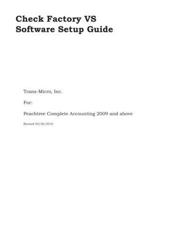
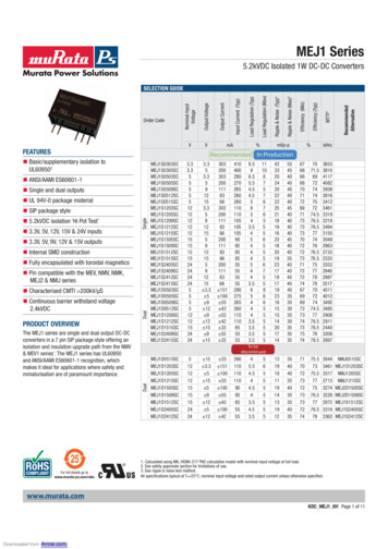
MEJ1 Series5.2kVDC Isolated 1W DC-DC ConvertersTOLERANCE ENVELOPESThe voltage tolerance envelope shows typical load regulation characteristics for this product series. The tolerance envelope is the maximum output voltage variation due tochanges in output loading.DUAL 1209, 1509, 24095%2%-1%Output VoltageOutput VoltageDUAL 1203, 1515, 2412, SINGLE 0303, 0305, 12033%1%0%-3%-7%102550751001025Output Load Current (%)0%-5%5075Output VoltageOutput VoltageDUAL 1512, SINGLE 1212, 1512, 24122%-1%252%0%0%-4%1001025Output Load Current (%)-4%5075100Output VoltageOutput Voltage-1%Output Load Current (%)75100DUAL 1212, 1215, 2415, SINGLE 0509, 0512, 1215, 24092%1%2550Output Load Current (%)DUAL 0512, SINGLE 1209, 15091010075Output Load Current (%)DUAL 0515, SINGLE 1515, 241510505%2%-1%-4%10255075100Output Load Current (%)www.murata.comKDC MEJ1 I01 Page 6 of 11Downloaded from Arrow.com.
MEJ1 Series5.2kVDC Isolated 1W DC-DC ConvertersTOLERANCE ENVELOPES (Continued)DUAL 1205, 0505, 1505, 24054%2%0%-3%10255075Output VoltageOutput VoltageSINGLE 1205, 1505, 2405, 05151005%3%1%-2%10Output Load Current (%)255075100Output Load Current (%)Output VoltageDUAL 0509, 0503, SINGLE 0503, 05056%1%1%-4%10255075100Output Load Current (%)Output Power (W)TEMPERATURE DERATING GRAPH1.00.50.2-40SafeOperating Area04085Ambient Temperature (ºC)www.murata.comKDC MEJ1 I01 Page 7 of 11Downloaded from Arrow.com.
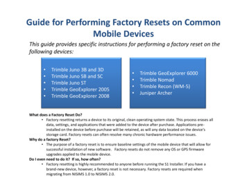
MEJ1 Series5.2kVDC Isolated 1W DC-DC ConvertersEFFICIENCY VS LOAD Single Output5V Input907070Efficiency (%)Efficiency (%)3.3V 0203040506070809010001020304012V EJ1S1512SCMEJ1S1215SCMEJ1S1515SC1007015V Input90Efficiency (%)Efficiency (%)50Load (%)Load (%)100102030405060708090100Load (%)001020304050607080Load (%)24V Input90Efficiency 5SC1000102030405060708090100Load (%)www.murata.comKDC MEJ1 I01 Page 8 of 11Downloaded from Arrow.com.
MEJ1 Series5.2kVDC Isolated 1W DC-DC ConvertersEFFICIENCY VS LOAD Dual Output12V Input90707050Efficiency (%)Efficiency (%)5V 0010203040Load (%)15V EJ1D1515SCMEJ1D2415SC1007024V Input90Efficiency (%)Efficiency (%)50Load (%)1001020304050Load (%)60708090100001020304050607080Load (%)www.murata.comKDC MEJ1 I01 Page 9 of 11Downloaded from Arrow.com.
MEJ1 Series5.2kVDC Isolated 1W DC-DC ConvertersPACKAGE SPECIFICATIONSMECHANICAL DIMENSIONSPIN CONNECTIONSSingle OutputPinFunction1257 Vin-Vin-Vout VoutDual OutputPinFunction1256*7 VIN-VIN-VOUTOV VOUT*All dimensions in mm 0.25mm (inches 0.01). All pins on a 2.54 (0.1) pitch and within 0.25 (0.01) of true position.* Pin not fitted on single output variants.6.00TUBE OUTLINE DIMENSIONS(0.236)Weight: 4.3gRECOMMENDED FOOTPRINT DETAILS14.20 (0.559)5.00 (0.197)*5.20 (0.205)1.50 (0.059)0.6 0.15(0.024 0.006)Unless otherwise stated all dimensions in mm 0.5mm (inches 0.02).Tube length : 20.669 0.079 (525mm 2mm).Tube Quantity : 25* Hole not required for single output variants.All dimensions in mm 0.25mm (inches 0.01).www.murata.comKDC MEJ1 I01 Page 10 of 11Downloaded from Arrow.com.
MEJ1 Series5.2kVDC Isolated 1W DC-DC ConvertersDISCLAIMERUnless otherwise stated in the datasheet, all products are designed for standard commercial and industrial applications and NOT for safety-critical and/or life-criticalapplications.Particularly for safety-critical and/or life-critical applications, i.e. applications that may directly endanger or cause the loss of life, inflict bodily harm and/or loss or severedamage to equipment/property, and severely harm the environment, a prior explicit written approval from Murata is strictly required. Any use of Murata standard products for any safety-critical, life-critical or any related applications without any prior explicit written approval from Murata shall be deemed unauthorised use.These applications include but are not limited to: Aircraft equipment Aerospace equipment Undersea equipment Power plant control equipment Medical equipment Transportation equipment ( automobiles, trains, ships, etc.) Traffic signal equipment Disaster prevention / crime prevention equipment Data Processing equipmentMurata makes no express or implied warranty, representation, or guarantee of suitability, fitness for any particular use/purpose and/or compatibility with any application or device of the buyer, nor does Murata assume any liability whatsoever arising out of unauthorised use of any Murata product for the application of the buyer. Thesuitability, fitness for any particular use/purpose and/or compatibility of Murata product with any application or device of the buyer remain to be the responsibility andliability of the buyer.Buyer represents and agrees that it has all the necessary expertise to create and implement safeguards that anticipate dangerous consequences of failures, monitor failures and their consequences, lessen the likelihood of failures that might cause harm, and take appropriate remedial actions. Buyer will fully indemnify and holdMurata, its affiliated companies, and its representatives harmless against any damages arising out of unauthorised use of any Murata products in any safety-critical and/or life-critical applications.Remark: Murata in this section refers to Murata Manufacturing Company and its affiliated companies worldwide including, but not limited to, Murata Power Solutions.This product is subject to the following operating requirementsand the Life and Safety Critical Application Sales Policy:Refer to: ementsMurata Power Solutions (Milton Keynes) Ltd. makes no representation that the use of its products in the circuits described herein, or the useof other technical information contained herein, will not infringe upon existing or future patent rights. The descriptions contained herein donot imply the granting of licenses to make, use, or sell equipment constructed in accordance therewith. Specifications are subject to changewithout notice. 2021 Murata Power Solutions (Milton Keynes) Ltd.www.murata.comKDC MEJ1 I01 Page 11 of 11Downloaded from Arrow.com.
ISOLATION VOLTAGE Hi Pot Test , Flash Tested , Withstand Voltage , Proof Voltage , Dielectric Withstand Voltage & Isolation Test Voltage are all terms that relate to the same thing, a test voltage, applied for a speci ed time, across a component designed to provide electrical isolation, to verify the integrity of that isolation.