Transcription
Basic Welding SymbolsandTheir Location Significance
ObjectivesAfter completing this chapter, the student should be able to: Understand the basics of welding symbolsList the major parts of a welding symbolInterpret weld locationsInterprets welding symbol information 2012 Delmar, Cengage Learning
Welding Symbols Enable a designer to indicate detailed information– Shorthand language– Standardized by AWS– Tail is added to the basic symbol for placement ofspecific information 2012 Delmar, Cengage Learning
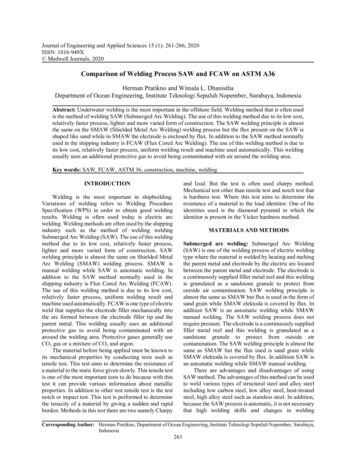
Reference Line (Required element)Always Horizontal
Reference Line (Required element)Arrow
Reference Line (Required element)ArrowTail
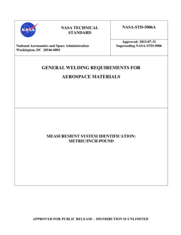
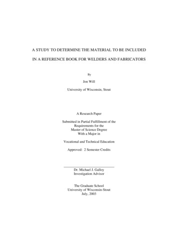
Reference Line must always be horizontal,Arrow points to the line or lines on drawing which clearly identify the proposed joint orweld area.Reference Line (Required element)ArrowTailThe tail of the welding symbol is used to indicate the welding or cutting processes,as well as the welding specification, procedures, or the supplementary informationto be used in making the weld.
FIGURE 20-19 Locations of specifications, processes,and other references on weld symbols. Cengage Learning 2012 2012 Delmar, Cengage Learning
Location Significance of Arrow Fillet and groove welding symbols– Arrow connects welding symbol reference line toone side of the joint Joint illustrated as a single line– Arrow of a symbol is directed to the line– Arrow side of joint is the near side of the joint Plug, slot, spot, seam, resistance, flash, upset, orprojection symbols– Arrow connects reference line to outer surface 2012 Delmar, Cengage Learning
Indicating Types of Welds Weld type roovesFlangePlugSlotSpot or projectionSeamBack or backingSurfacing 2012 Delmar, Cengage Learning
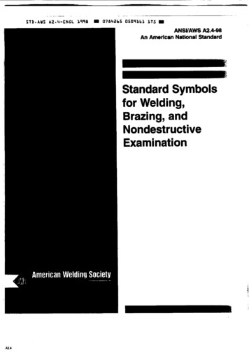
Weld Location Arrow side, other side, and both sides– Used to indicate the weld location Weld deposited on arrow side– Symbol placed below the reference line Weld deposited on the other side of the joint– Symbol is placed above Tail is added to designate welding specifications 2012 Delmar, Cengage Learning
OTHER SIDEARROW SIDE
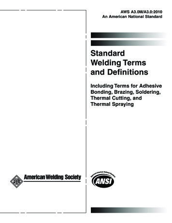
Fillet Weld Symbol Notice the Vertical lineIs alwayslocated on the Left! And the angled line it leanstowards the reference line.Arrow SideOther SideBoth SidesNo Arrow side orOther side SignificanceNot Used
Fillet Welds Dimensions of fillet welds– Shown on same side of reference line as weldsymbol Size of a fillet weld with unequal legs– Shown in parentheses to left of symbol Intermittent fillet welds– Length and pitch increments are placed to the right– Used to reduce amount of welding, possible welddistortion, and to prevent a crack from spreading 2012 Delmar, Cengage Learning
Plug or Slot Rectangle shapeArrow SideOther SideBoth SidesNo Arrow side orOther side SignificanceNot UsedNot Used
Plug Welds Holes in arrow side member of a joint for plugwelding– Indicated by placing weld symbol below thereference line Holes in the other side member– Indicated by placing weld symbol above the line Diameter or size– Located to the left of the symbol 2012 Delmar, Cengage Learning
Spot or Projection Resistance welderArrow SideOther SideBoth SidesNo Arrow side orOther side SignificanceNot Used
Spot Welds Dimensions of resistance spot welds– Indicated on same side of reference line as theweld symbol– Dimensioned by size or strength Size: designated as weld diameter Strength: shown as minimum shear strength inpounds per spot and is shown to the left of thesymbol 2012 Delmar, Cengage Learning
Stud Stud – nail/boltArrow SideOther SideNot UsedBoth SidesNot UsedNo Arrow side orOther side SignificanceNot Used
SeamArrow SideOther SideBoth SidesNo Arrow side orOther side SignificanceNot Used
Seam Welds Dimensions of seam welds– Shown on same side of reference line as the weldsymbol– Size is shown with or without the inch marks to theleft of the weld symbol– Strength is designated as minimum acceptableshear strength in pounds per linear inch 2012 Delmar, Cengage Learning
Back or BackingArrow SideOther SideBoth SidesNo Arrow side orOther side SignificanceNot UsedNot Used
Backing Piece of metal placed on back side of a weld joint– Must be thick enough to withstand the heat of theroot pass– May be used on butt joints, tee joints, and outsidecorner joints– May be left on the finished weld or removed 2012 Delmar, Cengage Learning
SurfacingArrow SideOther SideNot UsedBoth SidesNot UsedNo Arrow side orOther side SignificanceNot Used
EdgeArrow SideOther SideBoth SidesNo Arrow side orOther side SignificanceNot Used
Flanged Welds Weld symbols used where edges joined are bentto form a flange– Edge flange: shown by edge flange weld symbol– Corner flange welds: indicated by corner flangeweld symbol– Dimensions: shown on same side of reference lineas weld symbol– Size of flange weld: shown by a dimension placedoutward from flanged dimensions 2012 Delmar, Cengage Learning
Groove Welds Joint strength– Can be improved by making some type of groovepreparation– Seven types of grooves Can be made in one or both plates or on one or bothsides Cutting the groove: weld can penetrate deeper Can be cut in base metals in a number of ways 2012 Delmar, Cengage Learning
SquareArrow SideOther SideBoth SidesNo Arrow side orOther side Significance
VArrow SideOther SideBoth SidesNo Arrow side orOther side SignificanceNot Used
BevelArrow SideOther SideBoth SidesNo Arrow side orOther side SignificanceNot Used
UArrow SideOther SideBoth SidesNo Arrow side orOther side SignificanceNot Used
JArrow SideOther SideBoth SidesNo Arrow side orOther side SignificanceNot Used
Flare-VArrow SideOther SideBoth SidesNo Arrow side orOther side SignificanceNot Used
Flare-BevelArrow SideOther SideBoth SidesNo Arrow side orOther side SignificanceNot Used
Scarf for Brazed JointArrow SideOther SideBoth SidesNo Arrow side orOther side SignificanceNot Used
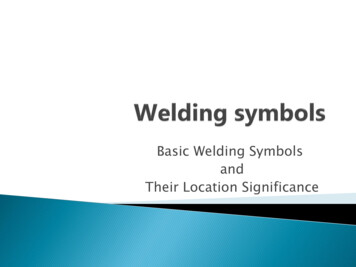
Weld all AroundField weldMelt thruConsumable Insert(Square)Backing/Spacer (Rectangular)ContourFlush or FlatBackingSpacerConvexConcave
A circle at the tangent of the arrow and the reference linemeans welding to be all around.
A flag at the tangent of the reference line and arrowmeans Field Weld.
1/41/4
Depth ofpreparation orgroove1/4 (5/16)1/4 (5/16)Depth of penetration
5/165/16
Weld both sides each end and 10inches center to center in between1/42-101/42-1010 in
Weld ends than 10 inch centers staggered each side1/42-101/42-1010 in10 in
Code or Standards Requirements Type, depth angle, and location of the groove– determined by a code or standard Welder skill– Can be a limiting factor in joint design Acceptable cost– Joint design: one major way to control welding cost 2012 Delmar, Cengage Learning
Summary Welding symbols– Meanings must be interpreted– Understanding prevents over-welding– Weldments must be flexible within limits 2012 Delmar, Cengage Learning
Fillet and groove welding symbols –Arrow connects welding symbol reference line to one side of the joint Joint illustrated as a single line –Arrow of a symbol is directed to the line –Arrow side of joint is the near side of the join