Transcription
This international standard was developed in accordance with internationally recognized principles on standardization established in the Decision on Principles for theDevelopment of International Standards, Guides and Recommendations issued by the World Trade Organization Technical Barriers to Trade (TBT) Committee.Designation: F711 17Standard Specification forFiberglass-Reinforced Plastic (FRP) Rod and Tube Used inLive Line Tools 1This standard is issued under the fixed designation F711; the number immediately following the designation indicates the year of originaladoption or, in the case of revision, the year of last revision. A number in parentheses indicates the year of last reapproval. A superscriptepsilon ( ) indicates an editorial change since the last revision or reapproval.1. Scope3. Terminology1.1 This specification covers insulating rods and foam-filledtubes made from fiberglass-reinforced plastic (FRP) that areintended for use in live line tools.3.1 Definitions of Terms Specific to This Standard:3.1.1 acceptance test—a type of test made at the option ofthe purchaser.3.1.2 design test—a type of test made on a sample treated asrepresentative of an industrial product. These tests will notgenerally be repeated in quantity production.3.1.3 insulating tubes and rods—fiberglass-reinforced plastic (FRP) products manufactured using processes so that thetubes and rods produced will meet the electrical and mechanical tests prescribed in this specification.3.1.4 interior foam-filled tube—homogeneous unicellularthermosetting foam filling with closed cells blown with noncombustible gases. The foam filling shall be bonded to theinterior tube wall. The foam filling should be free of voids,separations, holes, cracks, etc.3.1.5 routine test—a type of test made regularly on production material.3.1.6 visual inspection—a visual check made to detectconstructional defects.1.2 This specification does not include insulating foamfilled tubes and rods from other materials. Specifications forfittings and attachments to rods and foam-filled tubes forcomplete tools are not covered in this specification.1.3 This specification establishes the technical characteristics that the tubes and rods must satisfy.1.4 The following safety hazards caveat pertains only to thetest method portion, Section 12, of this specification. Thisstandard does not purport to address all of the safety concerns,if any, associated with its use. It is the responsibility of the userof this standard to establish appropriate safety, health, andenvironmental practices and determine the applicability ofregulatory limitations prior to use.1.5 This international standard was developed in accordance with internationally recognized principles on standardization established in the Decision on Principles for theDevelopment of International Standards, Guides and Recommendations issued by the World Trade Organization TechnicalBarriers to Trade (TBT) Committee.4. Ordering Information4.1 Outside Diameter Sizes—Foam-filled FRP tube andsolid FRP rod shall meet the outside diameter dimensionsshown in Table 1. The tolerances shown will assist in ensuringinterchangeability with interfacing equipment.2. Referenced Documents2.1 ASTM Standards:2D149 Test Method for Dielectric Breakdown Voltage andDielectric Strength of Solid Electrical Insulating Materialsat Commercial Power FrequenciesD638 Test Method for Tensile Properties of PlasticsD695 Test Method for Compressive Properties of RigidPlastics4.2 Inspection of the material shall be agreed upon betweenthe purchaser and the seller as part of the purchase contract.5. Materials and Manufacture5.1 Except for those test methods leading to destruction,neither the FRP tube, foam, or the bond between them shalldeteriorate during the prescribed mechanical and electricaltests of this specification.1This specification is under the jurisdiction of ASTM Committee F18 onElectrical Protective Equipment for Workers and is the direct responsibility ofSubcommittee F18.35 on Tools & Equipment.Current edition approved Nov. 1, 2017. Published December 2017. Originallyapproved in 1981. Last previous edition approved in 2013 as F711 – 02 (2013).DOI: 10.1520/F0711-17.2For referenced ASTM standards, visit the ASTM website, www.astm.org, orcontact ASTM Customer Service at service@astm.org. For Annual Book of ASTMStandards volume information, refer to the standard’s Document Summary page onthe ASTM website.6. Physical Requirements6.1 The materials shall conform to the diameters prescribedin Table 1 for tube and rod.6.2 The standard sizes listed by nominal diameter arerecommended and do not preclude the manufacture of othersizes or shapes.Copyright ASTM International, 100 Barr Harbor Drive, PO Box C700, West Conshohocken, PA 19428-2959. United States1
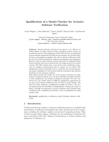
F711 17TABLE 1 Standard Tube and Rod Outside DiametersTYPETubeRodNominal DiameterMin Diameterin.(mm)in.(mm)in.(mm)11 1 41 1 21 3 422 1 233 81 25 83 routineroutineVisualMax 10.2 Electrical:TestDielectric current (leakage)(before moisture conditioning)Dielectric current (leakage)(after moisture conditioning)Withstand (either method 1 or 2)7. . Number of Tests and Samples (Three each)7.1 It has not been found necessary to specify the weight ofthe product produced under this specification in order for it tocomply with performance requirements.11.1 Tubes:11.1.1 Wicking Test—Three samples, each 1-in. (25-mm)long.11.1.2 Bending Deflection Test—8 ft, 5 in. (2.6 m) or longer.See Fig. 13.11.1.3 Horizontal Crush Test—Three diameters long. SeeFig. 14.11.1.4 Tension Test—12-in. (300-mm) long, prepared inaccordance with Fig. 1 and Test Method D638.8. Workmanship, Finish, and Appearance8.1 The external surface shall be uniform, symmetrical, andfree of abrasions, scratches, blemishes, and surface defects.8.2 Any defect that may capture an impurity or impair thedielectric integrity of the product shall be cause for rejection.8.3 FRP rod or tube material after which a finish coating,such as paint, is applied must meet all physical, electrical, andmechanical requirements.9. Sampling9.1 Design Test—Perform the test on a minimum of threesamples only when changes are made to a new or existingdesign of the product that may affect the mechanical andelectrical characteristics.9.1.1 The design test will be used to qualify a specific itemand normally will not be repeated during production.9.2 Sample Test—A test specimen shall consist of one ormore items, dependent on 1 % of the lot being tested.9.2.1 A lot is represented either by all items produced in oneproduction run or in one shipment.9.2.2 Lots of new, unused items shall have test specimensselected at random.9.3 Routine Test—Perform the test on all pieces delivered tothe purchaser.9.4 Acceptance Test—A test made at the option of thepurchaser.10. Conduct of Tests on Samples10.1 Mechanical:TestWickingBending deflectionHorizontal crushTensionShearCompressionModulus of elasticity (tension)Mechanical aging eFIG. 1 Tension Test2
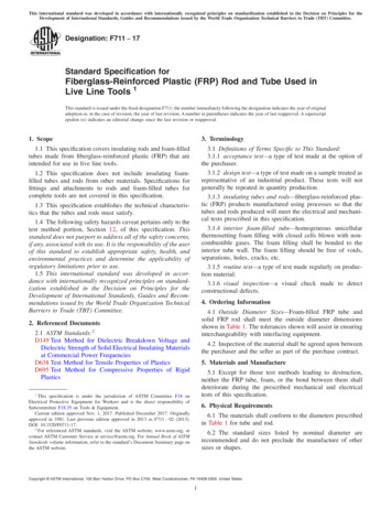
F711 1712.2.3.1 After initial cleaning, the sample shall remain inthe ambient atmosphere of the test premises for at least 24 h.12.2.4 Electrical Design Test—The sample for the dielectrictest shall be 12 in. (300 mm) in length.12.2.4.1 The electrical design tests shall be made before andafter exposure to moisture conditions, as specified, using 60-Hzvoltage.12.2.4.2 A typical test setup is shown in Fig. 3. Details areshown in Figs. 4-9. The measuring equipment should not beless than 6 ft (1.8 m) from the high-voltage electrode. Shieldand ground the assembly for the measuring equipment. Vertically mount the test specimen at least 3 ft (0.9 m) above thefloor on an insulating support. Apply the voltage of 100 kV rmsat 60 Hz between the electrodes, in accordance with TestMethod D149 at a maximum voltage rise of 3000 V/s. Measurethe current passing over or through the test specimen in rmsvalues by passing it through a known resistance.(a) The current I1 is the maximum dielectric currentmeasured with an alternating voltage of 100 kV rms 60 Hzapplied between the electrodes for 1 min.(b) Upon completion of the before-moisture conditioningelectrical test (I1), the sample shall then be placed in a suitablechamber and undergo the following conditioning prior to theafter-moisture conditioning electrical test, (I2).11.1.5 Shear Test—4-in. (100-mm) long, prepared in accordance with Fig. 2.11.1.6 Electrical Tests—12-in. (300-mm) long, prepared inaccordance with Section 12.11.2 Rod:11.2.1 Compression Test (Applicable to solid rod only)—4-ft (1.2-m) long, prepared in accordance with Test MethodD695.11.2.2 Modulus of Elasticity (Tension) (Applicable to solidrod only)—4-ft (1.2-m) long, prepared in accordance with TestMethod D638.11.3 Rod and Tube Mechanical Aging Tests:11.3.1 Flexure—Rod, 4 ft (1.2 m) or tube, 8 ft (2.4 m) inlength.12. Test Methods12.1 Visual Inspection—Make a visual check to detectmanufacturing defects (for example, evidence of faulty bonding between fibers and resin, air bubbles, foreign bodies, orparticles).12.2 Electrical Tests—The test apparatus shall be designedto provide the operator full protection in the performance of hisduties and provide reliable means of de-energizing and grounding the high voltage circuit.12.2.1 During the course of the testing, there shall be nosign of flashover or puncture on any of the samples.12.2.2 The ambient temperature for the test location shallnot be lower than 60 F (16 C).12.2.3 Prior to the first or initial electrical test, the sampleshall be cleaned with a suitable solvent as recommended by themanufacturer (specifically a solvent that neither destroys thematerials from which the tube or rod is made nor leaves anyresidue on the surface of the sample).Time:Temperature:Relative humidity:168 h23 4 C93 %, or greater(c) After moisture conditioning and a light wiping with adry cloth, the current I2 is measured under the same conditionsas was I1.(d) Locate the specimen in the same relative position toearth; the high-potential end of the sample shall be the same forboth tests.12.2.4.3 Test Results—The currents (I1) measured shall beless than the values in Table 2. The difference between I1 andI2 shall be less than 20 µA.12.2.5 Electrical Withstand Routine Tests—Either Method 1or Method 2 shall be used to perform the routine electricalwithstand test for both FRP rods and FRP foam-filled tubes.12.2.5.1 Electrical Withstand Acceptance Test (Method 1)Without Dielectric Current Monitoring—The typical test setupis shown in Fig. 10. Horizontally mount the test specimen atleast 3 ft (0.9 m) above the floor on an insulating support. Theelectrodes shall be spaced 12 in. apart.(a) During the electrical withstand acceptance test, thetubes or rods shall be subjected to an alternating voltage of 100kV rms at power frequency in accordance with Test MethodD149 at a maximum voltage rise of 3000 V/s. The test voltageshall be applied between electrodes for 5 min.(b) During the course of the testing, there shall be no signof flashover, puncture, tracking, or erosion on the surface ofany sample. There shall be no perceptible temperature rise ofany sample.12.2.5.2 Electrical Withstand Test (Method 2) With Dielectric Current Monitoring—The typical test set-up is shown inFigs. 11 and 12. The necessary equipment should be adequatelyshielded to provide accurate readings. The test fixture shouldbe enclosed for worker protection and equipped with anFIG. 2 Shear Test3
F711 17NOTE 1—For details of Fig. 3 see Figs. 4-9.FIG. 3 Typical AC Test Set UpFIG. 4 Assembly Detailexhaust fan to provide a stable atmosphere. A motor driveshould be utilized to ensure a uniform rate of feed. The feedrate should be proportional to the response time of the meteringcircuit; that is, it shall be run slowly enough that maximumreadings are obtained. At no time should this rate of feedexceed 40 ft/min.(a) With 6-in. electrode spacing, the applied voltage willbe 50 kV. The equipment shall be designed such that aflashover, excessive dielectric current will disable the motordrive so that intentional action on the part of the operator isrequired to reset the equipment.(b) Acceptable rise above ambient of less than I1 as listedin Table 2. During the course of the testing, there shall be nosign of flashover, puncture, tracking, or erosion on the surfaceof any sample.12.3 Mechanical Testing of FRP Tube:12.3.1 Bending Deflection Test (design)—A tube 8 ft 5 in.(2.6 m) or longer shall be placed in a testing device such thatthe overhang arm is 60 in. (1.5 m) in length, and the distancebetween supports is as shown in Fig. 13.4
F711 17FIG. 5 Electrode DetailFIG. 6 Electrode Cap Detail12.3.1.1 The support shall be of the pole clamp-type (approximately 4-in. (100-mm) long) with the back clamp tightened to hold specimen in place while the front clamp remainsloose and serves only as a fulcrum. Both clamps shall be freeto pivot as load (in Table 3) is applied 60 in. (1.5 m) fromcenter of front clamping device (see Fig. 13).FIG. 7 Brass Electrode Detail12.3.1.2 The deflection of each tube tested shall not exceedthe value specified in Table 3.5
F711 1712.3.2.2 The distance between the two plates is then continuously decreased at a constant rate between 0.08 to 0.2 in. (2to 5 mm)/min. Once selected this constant rate shall not bechanged for that test.NOTE 1—It is recognized that horizontal crush tests performed at ahigher constant displacement rate are more severe.12.3.2.3 Record the constant displacement rate selected.Record the maximum force applied to the test specimen duringthe first 0.25-in. (6-mm) displacement. All tubes shall becapable of exhibiting a crush strength equal to or in excess ofminimum values listed in Table 4.12.3.3 Tension Test (design)—The FRP tube shall exhibitaxial tension strength equal to or in excess of the minimumvalues listed in Table 5. Cut the test specimens from the wallof a tube and accurately measure to permit cross section areacalculations within 5 % of true value and in accordance withTest Method D638 (see example in Fig. 1). The tensile strengthof a tube is the product of the specimen ultimate load and theratio of the area of the entire tube wall cross section to that ofthe test specimen. At the manufacturer’s option, the completetube may be loaded to the tensile minimum of Table 5. Whenthis option is chosen, the specimen length and holding meansare optional with the manufacturer.12.3.4 Shear Test (design)—FRP tube shall have a minimumaverage shear strength, parallel to the axis of the tube, asindicated in Table 6. Place the specimens between flat andparallel blocks for testing. Test two specimens from the sametube, with the shear planes radially separated by approximately90 . Apply the testing force at a crosshead speed of 0.2 in. (5mm)/per min. Record the maximum load at the point thesample shears (see example in Fig. 2).FIG. 8 Nylon Electrode Support Detail12.4 Mechanical Test of Solid Rod (design)—The tensilestrength of the rod in the direction of the fibers, when tested inaccordance with Test Method D638, shall be 80 000 psi (550MPa) minimum. Compressive strength of the rod in thedirection of the fibers, when tested in accordance with TestMethod D695, shall be 30 000 psi (205 MPa) minimum. Therod tensile modulus of elasticity when tested in accordancewith Test Method D638 shall be 1.5 106 minimum.12.5 Mechanical Aging Test (design)—Submit specimens oftubes and rods to cycles of simple flexure as described below.Each test is to be made on three specimens at environmentaltemperature of 60 F (16 C) minimum.12.5.1 Flexure—Place a tube 8-ft (2.4-m) long or a rod 4-ft(1.2-m) long between two supports consisting of pulleys (seeFig. 15), the support points being separated as follows:FIG. 9 Brass Screw Detail20 in. for solid rod60 in. for 1 in., 11 4 in. tube80 in. for 11 2 in. tube and larger12.3.2 Horizontal Crush Test (design)—The test specimensshall be three nominal diameters in length. Each specimen shallbe tested separately. Each specimen shall be placed betweensmooth, flat, parallel, and rigid plates for the test (see Fig. 14).The length of the plates shall be at least equal to the specimenlength plus 3 4 in. (19 mm).12.3.2.1 Reduce the distance between the two plates until aforce, not greater than 20 lb, registers on the load instrumentation. Zero all instrumentation.0.5 m for solid rod1.5 m for 32 mm tube2.0 m for 39 mm tube and larger12.5.1.1 At the center of the span, apply a vertical force toa fiber strap 2-in. (50-mm) wide, placed on the tube. The testconsists of submitting each specimen to 1000 cycles of flexurein each quadrant by applying the force specified in Table 2.12.5.1.2 The flexure frequency during the test shall bebetween 1 and 5 cpm. After completion of the test, the tubesand rods shall reveal no visible signs of deterioration, bearingsurfaces excluded.6
F711 17TABLE 2 Flexure Forces and Leakage Current ATYPETubeRodOutside DiameterWall Thicknessin.(mm) 0.10 OD111 1 41 1 41 1 21 1 21 3 41 3 4222 1 22 1 2333 81 25 83 9)(19.1) 0.100 in. (2.54 mm)Flexure Forces 0.10 OD 0.100 in. (2.54 mm) 0.125 in. (3.18 mm) 0.125 in. (3.18 mm) 0.150 in. (3.81 mm) 0.150 in. (3.81 mm) 0.175 in. (4.45 mm) 0.175 in. (4.45 mm) 0.200 in. (5.08 mm) 0.200 in. (5.08 mm) 0.250 in. (6.35 mm) 0.250 in. (6.35 mm) 0.300 in. (7.62 mm) 0.300 in. (6.35 mm)Leakage Current, 3.0)(7473.0)(13 478.1)(13 20122414286666AValues listed for maximum I1 are based on pole constructed of a relatively thin wall and filled internally with foam. Some special applications require a thicker wall, denserfoam, or different materials, which could change the dielectric constant of the test setup and consequently I1. Tubes such as these will still meet the requirements of thisspecification if the dry leakage is less than twice the listed maximum value of I1 in the table.FIG. 10 Typical Test Arrangement for Electrical Withstand Acceptance Test12.5.2 Wicking Test (design)—Take three samples, each1-in. (25-mm) long from midspan of mechanically aged tubes,and immerse them in Superior Viking Quick Drying Ink orequal with 50/50 ink/water solution to a minimum depth of 1 2in. (12 mm). After 24 h in the ink solution, no wicking shall beobserved at the free end of the 1-in. (25-mm) sample.FIG. 11 Typical Test Set-Up12.6 Dimensional Check (Routine)—Measure the diametersto verify conformity with the requirements of Table 1.tured and tested in accordance with this specification, togetherwith a report of the test results, shall be furnished at the timeof shipment.13. Rejection and Rehearing13.1 Material that fails to conform to the requirements ofthis specification may be rejected. Rejection should be reportedto the producer or supplier promptly and in writing. In case ofdissatisfaction with the results of the test, the producer orsupplier may request another test in the presence of hisrepresentative, and such a request should be granted.15. Packaging, Marking, Shipping, and Preservation15.1 Finished tubes and rods shall carry the followinginformation affixed to the item in a manner that does not affectthe performance:15.1.1 Name of manufacturer,15.1.2 Month and year of manufacture, and15.1.3 That the product meets the requirements and bearsthe designated number of this specification.14. Certification14.1 Upon request of the purchaser in the contract or order,a manufacturer’s certification that the material was manufac-7
F711 17TABLE 4 Crush MinimumsDiameterMin Crush Strengthin.(mm)lbf(N)11 1 41 1 21 3 422 1 500(2891)(3336)(3559)(3781)(3959)(5382)(6672)TABLE 5 Tensile Minimums for FRP TubesDiameterMin Tensile Strengthin.(mm)11 1 41 1 21 3 422 1 82942436499000000000000000000000(N)(62 275.1)(80 068.0)(12 8998.4)(18 6825.3)(19 1273.5)(28 4686.2)(44 0374.0)FIG. 12 Typical Test Set-UpTABLE 6 Average Shear Minimums for FRP TubesDiameterFIG. 13 Bending Deflection TestTABLE 3 DeflectionOutside Diameterof TubeApplied Forcein.(mm)lbf(N)11 1 41 1 21 3 422 1 (667.2)Max 54.0)(139.7)(88.9)(44.5)(50.8)FIG. 14 Crush Test8Min Average Shear Strengthin.(mm)lbf(N)11 1 41 1 21 3 422 1 (3958.9)(4670.6)(6005.1)
F711 17FIG. 15 Mechanical TestsSUPPLEMENTARY REQUIREMENTSThe following supplementary requirement shall apply only when specified in the purchaser order.S1. AcceptanceS1.1.3 Electrical Tests—Tubes or rods selected shall withstand 100 kV at 60 Hz/12 in. (300 mm) for 5 min with amaximum rise of 3000 V/s or 50 kV at 60 Hz over a minimumlength of 6 in. (150 mm), andS1.1.4 Mechanical Tests—Tubes selected for mechanicaltests shall be subjected to the bending deflection test and theloading forces as prescribed in 12.3.1. Deflection shall notexceed values specified in Table 3.S1.1 At the option of the purchaser, all or any part of anorder of tubes or rods may be subjected to the followingchecks:S1.1.1 Visual check for general appearance, surfaceblemishes, air bubbles, or foreign bodies,S1.1.2 Dimensional checks,9
F711 17ASTM International takes no position respecting the validity of any patent rights asserted in connection with any item mentionedin this standard. Users of this standard are expressly advised that determination of the validity of any such patent rights, and the riskof infringement of such rights, are entirely their own responsibility.This standard is subject to revision at any time by the responsible technical committee and must be reviewed every five years andif not revised, either reapproved or withdrawn. Your comments are invited either for revision of this standard or for additional standardsand should be addressed to ASTM International Headquarters. Your comments will receive careful consideration at a meeting of theresponsible technical committee, which you may attend. If you feel that your comments have not received a fair hearing you shouldmake your views known to the ASTM Committee on Standards, at the address shown below.This standard is copyrighted by ASTM International, 100 Barr Harbor Drive, PO Box C700, West Conshohocken, PA 19428-2959,United States. Individual reprints (single or multiple copies) of this standard may be obtained by contacting ASTM at the aboveaddress or at 610-832-9585 (phone), 610-832-9555 (fax), or service@astm.org (e-mail); or through the ASTM website(www.astm.org). Permission rights to photocopy the standard may also be secured from the Copyright Clearance Center, 222Rosewood Drive, Danvers, MA 01923, Tel: (978) 646-2600; http://www.copyright.com/10
D149 Test Method for Dielectric Breakdown Voltage and . Withstand (either method 1 or 2) routine rod routine tube 11. Number of Tests and Samples (Three each) 11.1 Tubes: . 12.2.4 Electrical Design Test—The sample for the dielectric test shall be 12 in. (300 mm) in length.