Transcription
IDUINO for maker’s lifeUser ManualFor2.8" TFT Touch Shield for Arduino withResistive Touch Screen (TF028)
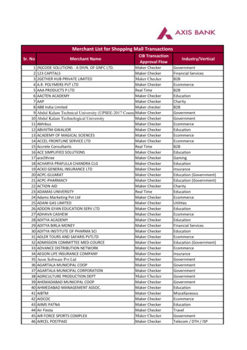
IDUINO for maker’s lifeDescription:This 2.8” TFT Touchscreen is designed to suitable for Arduino UNO/Mega2560. It candirectly plug inoto the UNO/Mega2560 board without any wiring and soldering.Library is compatible with Adafruit TFT touchscreen shield, which is easy to use . It hasway more resolution than a black and white 128x64 display. As a bonus, this displayhas a resistive touchscreen attached to it already, so you can detect finger pressesanywhere on the screen. 240x320 pixels with individual pixel control. Meanwhile, thismodule supports mini SD card to expand storage.Specification: 2.8" diagonal LCD TFT display240x320 resolutionILI9341 controller with built in video RAM bufferWorks with any Arduino '328 or Mega5V compatible! Use with 3.3V or 5V logicWith white LED backlight.Suport Mini SD card extensionSize: 78*52*16mmWeight: 38g
IDUINO for maker’s lifePinoutPINLCD RSTLCD CSLCD RSLCD WRLCD RDGND5V3V3LCD D0LCD D1LCD D2LCD D3LCD D4LCD D5LCD D6LCD D7DescriptionLCD Reset pinLCD Chip selectLCD Register selectLCD WriteLCD ReadGround5V3.3VLCD data bit 0LCD data bit 1LCD data bit 2LCD data bit 3LCD data bit 4LCD data bit 5LCD data bit 6LCD data bit 7www.openplatform.cc
IDUINO for maker’s lifeSD SSSD DISD DOSD SCKSD cardSD cardSD cardSD cardSlave selectSerial data InSerial data OutSerial clockExample:We have several cool projects as the example, such as text display, phone call andimage display. Here we use the phone call to show.Before uploading the code, you need install the library first. And no wire connection isneeded, just plug the Screen module on the UNO/Mega board.
IDUINO for maker’s life*******code begin*******#include Adafruit GFX.h // Core graphics library#include Adafruit TFTLCD.h // Hardware-specific library#include TouchScreen.h // The control pins for the LCD can be assigned to any digital or// analog pins.but we'll use the analog pins as this allows us to// double up the pins with the touch screen (see the TFT paint example).#define LCD CS A3 // Chip Select goes to Analog 3#define LCD CD A2 // Command/Data goes to Analog 2#define LCD WR A1 // LCD Write goes to Analog 1#define LCD RD A0 // LCD Read goes to Analog 0#define LCD RESET A4 // Can alternately just connect to Arduino's reset pin// When using the BREAKOUT BOARD only, use these 8 data lines to the LCD:// For the Arduino Uno, Duemilanove, Diecimila, etc.://D0 connects to digital pin 8//D1 connects to digital pin 9//D2 connects to digital pin 2//D3 connects to digital pin 3//D4 connects to digital pin 4//D5 connects to digital pin 5//D6 connects to digital pin 6//D7 connects to digital pin 7(Notice these areNOT in order!)// For the Arduino Mega, use digital pins 22 through 29// (on the 2-row header at the end of the board).// Assign human-readable names to some common 16-bit color values:#define BLACK0x0000#define BLUE0x001F
IDUINO for maker’s life#define RED0xF800#define GREEN0x07E0#define CYAN0x07FF#define MAGENTA 0xF81F#define YELLOW0xFFE0#define WHITE0xFFFF// Color definitions#define ILI9341 BLACK0x0000/*0,0,#define ILI9341 NAVY0x000F/*0,0, 128 */#define ILI9341 DARKGREEN0x03E0/*0, 128,#define ILI9341 DARKCYAN0x03EF/*0, 128, 128 */#define ILI9341 MAROON0x7800/* 128,0,#define ILI9341 PURPLE0x780F/* 128,0, 128 */#define ILI9341 OLIVE0x7BE0/* 128, 128,#define ILI9341 LIGHTGREY0xC618/* 192, 192, 192 */#define ILI9341 DARKGREY0x7BEF/* 128, 128, 128 */#define ILI9341 BLUE0x001F/*0,#define ILI9341 GREEN0x07E0/*0, 255,#define ILI9341 CYAN0x07FF/*0, 255, 255 */#define ILI9341 RED0xF800/* 255,0,#define ILI9341 MAGENTA0xF81F/* 255,0, 255 */#define ILI9341 YELLOW0xFFE0/* 255, 255,#define ILI9341 WHITE0xFFFF/* 255, 255, 255 */#define ILI9341 ORANGE0xFD20/* 255, 165,#define ILI9341 GREENYELLOW 0xAFE5#define ILI9341 PINK0xF81F/******************* UI details */#define BUTTON X 40#define BUTTON Y 100#define BUTTON W 60#define BUTTON H 30#define BUTTON SPACING X 20#define BUTTON SPACING Y 20#define BUTTON TEXTSIZE 2// text box where numbers go#define TEXT X 10#define TEXT Y 10#define TEXT W 220#define TEXT H 50#define TEXT TSIZE 3#define TEXT TCOLOR ILI9341 MAGENTA0 */0 */0 */0 */0, 255 *//* 173, 255,0 */0 */0 */0 */47 */
IDUINO for maker’s life// the data (phone #) we store in the textfield#define TEXT LEN 12char textfield[TEXT LEN 1] "";uint8 t textfield i 0;#define YP A3 // must be an analog pin, use "An" notation!#define XM A2 // must be an analog pin, use "An" notation!#define YM 9// can be a digital pin#define XP 8// can be a digital pin#define TS MINX 100#define TS MAXX 920#define TS MINY 70#define TS MAXY 900// We have a status line for like, is FONA working#define STATUS X 10#define STATUS Y 65#include MCUFRIEND kbv.h MCUFRIEND kbv tft;TouchScreen ts TouchScreen(XP, YP, XM, YM, 300);// If using the shield, all control and data lines are fixed, and// a simpler declaration can optionally be used:// Adafruit TFTLCD tft;Adafruit GFX Button buttons[15];/* create 15 buttons, in classic candybar phone style */char buttonlabels[15][5] {"Send", "Clr", "End", "1", "2", "3", "4", "5", "6", "7","8", "9", "*", "0", "#" };uint16 t buttoncolors[15] {ILI9341 DARKGREEN, ILI9341 DARKGREY, ILI9341 RED,ILI9341 BLUE, ILI9341 BLUE, ILI9341 BLUE,ILI9341 BLUE, ILI9341 BLUE, ILI9341 BLUE,ILI9341 BLUE, ILI9341 BLUE, ILI9341 BLUE,ILI9341 ORANGE, ILI9341 BLUE, ILI9341 ORANGE};void setup(void) {Serial.begin(9600);Serial.println(F("TFT LCD test"));#ifdef USE ADAFRUIT SHIELD PINOUTSerial.println(F("Using Adafruit 2.4\" TFT Arduino Shield Pinout"));
IDUINO for maker’s life#elseSerial.println(F("Using Adafruit 2.4\" TFT Breakout Board (tft.height());tft.reset();uint16 t identifier tft.readID();if(identifier 0x9325) {Serial.println(F("Found ILI9325 LCD driver"));} else if(identifier 0x9328) {Serial.println(F("Found ILI9328 LCD driver"));} else if(identifier 0x4535) {Serial.println(F("Found LGDP4535 LCD driver"));}else if(identifier 0x7575) {Serial.println(F("Found HX8347G LCD driver"));} else if(identifier 0x9341) {Serial.println(F("Found ILI9341 LCD driver"));}else if(identifier 0x7783) {Serial.println(F("Found ST7781 LCD driver"));}else if(identifier 0x8230) {Serial.println(F("Found UC8230 LCD driver"));}else if(identifier 0x8357) {Serial.println(F("Found HX8357D LCD driver"));} else if(identifier 0x0101){identifier 0x9341;Serial.println(F("Found 0x9341 LCD driver"));}else {Serial.print(F("Unknown LCD driver chip: "));Serial.println(identifier, HEX);Serial.println(F("If using the Adafruit 2.8\" TFT Arduino shield, the line:"));Serial.println(F("#define USE ADAFRUIT SHIELD PINOUT"));Serial.println(F("should appear in the library header (Adafruit TFT.h)."));Serial.println(F("If using the breakout board, it should NOT be #defined!"));Serial.println(F("Also if using the breakout, double-check that all wiring"));Serial.println(F("matches the tutorial."));identifier 0x9341;}
IDUINO for maker’s illScreen(BLACK);// create buttonsfor (uint8 t row 0; row 5; row ) {for (uint8 t col 0; col 3; col ) {buttons[col row*3].initButton(&tft, BUTTON X col*(BUTTON W BUTTON SPACING X),BUTTON Y row*(BUTTON H BUTTON SPACING Y),// x, y, w, h, outline,fill, textBUTTON W,BUTTON H,ILI9341 WHITE,buttoncolors[col row*3],ILI9341 WHITE,buttonlabels[col row*3], BUTTON TEXTSIZE);buttons[col row*3].drawButton();}}// create 'text field'tft.drawRect(TEXT X, TEXT Y, TEXT W, TEXT H, ILI9341 WHITE);}// Print something in the mini status bar with either flashstringvoid status(const FlashStringHelper *msg) {tft.fillRect(STATUS X, STATUS Y, 240, 8, ILI9341 BLACK);tft.setCursor(STATUS X, STATUS Y);tft.setTextColor(ILI9341 WHITE);tft.setTextSize(1);tft.print(msg);}// or charstringvoid status(char *msg) {tft.fillRect(STATUS X, STATUS Y, 240, 8, ILI9341 BLACK);tft.setCursor(STATUS X, STATUS Y);tft.setTextColor(ILI9341 WHITE);tft.setTextSize(1);tft.print(msg);}#define MINPRESSURE 10#define MAXPRESSURE 1000void loop(void) {/*TSPoint p;p ts.getPoint();*/
IDUINO for maker’s lifedigitalWrite(13, HIGH);TSPoint p ts.getPoint();digitalWrite(13, LOW);// if sharing pins, you'll need to fix the directions of the touchscreen pins//pinMode(XP, OUTPUT);pinMode(XM, OUTPUT);pinMode(YP, OUTPUT);//pinMode(YM, OUTPUT);// we have some minimum pressure we consider 'valid'// pressure of 0 means no pressing!// p ts.getPoint();/*if (ts.bufferSize()) {} else {// this is our way of tracking touch 'release'!p.x p.y p.z -1;}*/// Scale from 0- 4000 to tft.width using the calibration #'s/*if (p.z ! -1) {p.x map(p.x, TS MINX, TS MAXX, 0, tft.width());p.y map(p.y, TS MINY, TS MAXY, 0, tft.height());Serial.print("("); Serial.print(p.x); Serial.print(", ");Serial.print(p.y); Serial.print(", ");Serial.print(p.z); Serial.println(") ");}*/if (p.z MINPRESSURE && p.z MAXPRESSURE) {// scale from 0- 1023 to tft.widthp.x map(p.x, TS MINX, TS MAXX, tft.width(), 0);p.y (tft.height()-map(p.y, TS MINY, TS MAXY, tft.height(), 0));}// go thru all the buttons, checking if they were pressedfor (uint8 t b 0; b 15; b ) {if (buttons[b].contains(p.x, p.y)) {//Serial.print("Pressing: "); Serial.println(b);buttons[b].press(true);// tell the button it is pressed} else {buttons[b].press(false);// tell the button it is NOT pressed
IDUINO for maker’s life}}// now we can ask the buttons if their state has changedfor (uint8 t b 0; b 15; b ) {if (buttons[b].justReleased()) {// Serial.print("Released: "); Serial.println(b);buttons[b].drawButton();// draw normal}if (buttons[b].justPressed()) {buttons[b].drawButton(true);// draw invert!// if a numberpad button, append the relevant # to the textfieldif (b 3) {if (textfield i TEXT LEN) {textfield[textfield i] buttonlabels[b][0];textfield i ;textfield[textfield i] 0; // zero terminate// fona.playDTMF(buttonlabels[b][0]);}}// clr button! delete charif (b 1) {textfield[textfield i] 0;if (textfield 0) {textfield i--;textfield[textfield i] ' ';}}// update the current text fieldSerial.println(textfield);tft.setCursor(TEXT X 2, TEXT Y 10);tft.setTextColor(TEXT TCOLOR, ILI9341 BLACK);tft.setTextSize(TEXT TSIZE);tft.print(textfield);// its always OK to just hang upif (b 2) {status(F("Hanging up"));
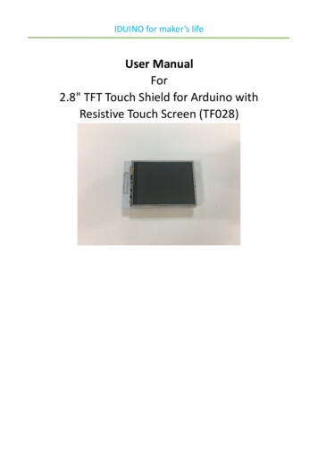
IDUINO for maker’s life//fona.hangUp();}// we dont really check that the text field makes sense// just try to callif (b 0) {status(F("Calling"));Serial.print("Calling "); );}delay(100); // UI debouncing}}}*******code End*******Upload the code, you’ll see the display as o-phone-arduino-powered-diy-cellphone
// D4 connects to digital pi. n 4 // D5 connects to digital pin 5 // D6 connects to digital pin 6 // D7 connects to digital pin 7 // For the Arduino Mega, use digital pins 22 through 29 // (on the 2-row header at the end of the board). // Assign human-readable names to some common 16-bit color values: #define. BLACK 0x0000. #define. BLUE 0x001F