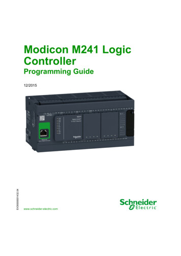
Transcription
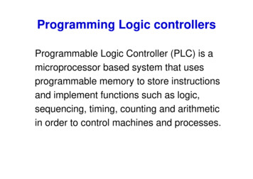
Programming Logic controllersProgrammable Logic Controller (PLC) is amicroprocessor based system that usesprogrammable memory to store instructionsand implement functions such as logic,sequencing, timing, counting and arithmeticin order to control machines and processes.
PLC Features PLC features can be concluded in thefollowing: They are rugged, withstand industrialenvironment, such as heat, humidity,mechanical shocks and vibrations The interfacing for inputs and outputs isinside the controller They are easily programmed PLC is capable of both logic and PID control.
Typical PLC
Forms of PLCs First developed in 1968, they are now widelyused: Two types: 1- Single – box type: for smallprogrammable controllers, is supplied as anintegral compact package, complete withpower supply, processor, memory andinput/output units. Typically they may have 6,8, 12, or 24 inputs and 4, 8, or 16, outputsand a memory store some 300-1000instructions. Eg. MELSEC FX3U 2- Rack mounted type: for all sizing ofprogramming controllers. It consists ofseparate modules for power supply,processor, input/output, etc. They aremounted on rails with a metal cabinet. E.g.SIMATIC S7-300/400
Input/output processing PLC is continuously running through its programand updating it as a result of the input signals,each such loop is called a cycle. Two methods of processing: 1- Continuous updating 2- Mass updating continuous updating: The cpu scanning the input channels as theyoccur in the program instructions. Each input isexamined individually (delay time 3 ms). Theoutput is latched so that they retain their statusuntil the next update
Input/output processingMass input/ output copying: itworks in the following process:1. Scan all the inputs and copyinto RAM2. Fetch and decode and executeall program instruction insequence, copying outputinstruction to RAM3- Once the program is executed,the CPU performs diagnostics andcommunication tasks4- update all outputsRepeat the sequence.
Input/Output address The inputs and outputs are identified by their addresses, the notation useddepending on the PLC manufacturer. This is the address of the input oroutput in the memory of the PLC. Its just a number preceded by a letter toindicate whether it is an input or an output With large PLCs having several racks of input and output and a number ofmodules in each rack, the rack and modules are numbered and so aninput or output is identified by its rack number followed by the number ofthe module in that rack and the number to show its terminal in the module.:The Allen-Bradley PLC-5has I: 012/03 to indicate aninput in rack 01 at module 2and terminal 03
PLC In Control oduleMicroprocessorInput ModulePLCOutput ModuleActuatorSensorProcess
Architecture of a PLCIt consist essentially of:Central processing unit: control allprocesses with frequency 1-8 M HzMemory: Buffers as temporary storage, ROMfor system data & RAM for user programInput/output interface:System buses
Input/output unit The input/output unit provides the interfacebetween the system and the outside world. The input/ output interface provides isolation andsignal conditioning functions so that sensors andactuators can often be directly connected tothem without the need for other circuitry. Out devices: motors, starting coils, solenoidvalve, etc Input devices: temperature sensors, flowsensors, encoders, etc
Input/output unitElectrical isolation from the external world isusually provided by means of opt isolators.Figure shows the basic form of input channelFigure 21.2Input channel
Input/output unit The digital signal that is compatible with themicroprocessor of the PLC is 5 volt dc however,signal conditioning in the input channel withisolation enables a wide range of input signals tobe supplied. Possible input voltages 5V, 24V,110V, and 240V. The output to the output unit is digital with alevel of 5 V, Three types of outputs are available: Relay type,Transistor type & triac type
Input/output unit Three types of outputs are available: Relay type: The signal from the PLC is used tooperate a relay and so able to switch currents ofa few amperes in an external circuit. The relayisolate the PLC from external world, can be usedfor AC and DC but they are slow Transistor type: It is used to switch currentthrough external circuit, fast opto-isolators areused to provide isolation, used only for DCswitching Triac type: used for both AC and DC Possible output from output channels: 24V,100mA; 100V dc,1 A; 240V,1A ac; or 240V, 2A ac
Inputting ProgramsAre entered into the input/output from:Small hand- held programming devices, desktopconsoles with a visual display or key board and screen
Inputting ProgramsOnly when the program has beendesigned and checked on theprogramming device is transferredto the memory of the PLCTypical Program memory size is(specified in term of steps) 300 to1000 step.Program step is an instruction forsome event to occur, ex: checkstatus of switch AAfter developing the program inRAM it may be transferredpermanently to the EPROM chip
Figure 21.3(a), (b) Sourcing, (c), (d) sinking
Ladder programmingThe form of programming commonly use with PLC isladder programming. Each program task is specified asthough a rung of a ladder.Thus a rung could specify that the state of switches Aand B be examined and if both A and B are closed thena solenoid, the output is energized.Figure 21.4(a), (b) Alternative ways of drawing an electric circuit,(c) comparable rung in a ladder program
Ladder programmingThe sequence followed by a PLC when carrying out a program:1- Scan the inputs associated with one rung of the ladder program2- solve the logic operation involving those inputs Set/ reset the outputs for that rung3- move on to the next rung and repeat operations 1, 2, 3.and so on until the end of program with each rung of the ladderscanned in turn. The PLC then goes back to the begining of the program and startsagain The ladder diagram consists of two vertical lines representing thepower rails.Circuits (rung) are connectedas horizontal lines,
Ladder programmingFig.21.5 shows a basic standared symbols that are used and rung,Inputs must always preceede outputs and there must be at least one outputon each lineEach rung must start with an input or series of inputs and end with an output
Ladder programmingExample of a ladder diagramFigure 21.6Switch controlling a solenoidThe output from the PLC is to energise a solenoid when a normallyopen start switch connnected to the input is activated by being closedThis might be a solenoid valve which opens to allow water to enter avessel.
Ladder programmingExample of a ladder diagram: An ON/OFF temperature controlFigure 21.7Temperature control systemThe input goes from low to high when the temparaturesensor reaches the set temperature. The output is thento go from ON to OFF.
Ladder programmingLogic FunctionsThe logic Functions canbe obtained bycombinations of switches.The Figures shows howladder programs can bewritten for such combinationAND circuitNOR circuitNAND circuitOR circuitXOR circuit
Ladder programmingLogic FunctionsThe basic logic functions can be used to obtained morecomplicated combinations of switches.Consider a situation where a normally open switch A must beactivated and either of two other, normally open switches Band C must be activated for a coil to be energised.Figure 21.9Switches controlling a solenoid
Figure 21.10Shop door system
PLC programming: Instruction List Each horizontal rung on the ladder represents aline in the program and the entire ladder givesthe complete program in the ladder language. Using a graphic interface, a programmer canbuild his program, then translate these symbolsinto machine language that can be stored in thePLC memory. Alternatively, the ladder program can betranslated into an instruction list and entered intothe programming panel or computer.
PLC programming: Instruction List Instruction lists consist of a series ofinstruction with each instruction being on aseparate line. An instruction consists of anoperator followed by one or more operand .e.g. LD A (*load input A*)Comments
Instruction ListThe mnemonics codes used by different PLC manufactures differ but aninternational standard (IEC 1131-3) has been proposed and is widely usedTable below shows core mnemonics. For the rest of the followinginstructions, Mitsubishi mnemonics will be usedTable 21.1Some Instruction code mnemonics
Instruction List and Logic FunctionFigures show how individual rungs on a ladder are entered using theMitsubishi mnemonics where logic functions are involvedFigure 21.11(a) AND, (b) OR, (c) NOR, (d) NAND
Instruction List and BranchingWhen two parallel arms are involved, Mitsubishi treats the situation byusing an ORB instruction to indicate OR together parallel branches asshown in Fig.21.12a. Line 3 describe a new line since it starts withLD/LDI instructionwhile Siemensuse brackets asshown inFig.21.12b,Figure 21.12XOR
Latching and internal relaysThe term latching is used for the circuit that able to holdthe output energized even though the input whichenergizing it ceases. So the output remember its last state.Figure 21.13A latch circuit
Latching: ExamplesIt is required for the PLC to control a motor so thatwhen the start signal button is momentarily pressedthe motor starts and when the stop button ispressed, the motor switches OFFFigure 21.14Stop system
Internal relays The term internal, auxiliary relay or marker isused for what can be considered as internalrelay in PLC. It behaves like relays with theirassociated contacts, but in reality are not actualrelays but simulation by the software of the PLC. Internal can be very useful aids in theimplementation of switching sequences. They are often used when there are programswith multiple input conditions.
Internal relays: examplesThey are used when there are programs with multiple input conditions.In Fig.21.15-a different input arrangement have been implemented byinternal RelayMultiple out can alsostarted with internalrelays as shown inFig.21.15-b(a) An output controlled by two input arrangements, (b) starting ofmultiple outputsFigure 21.15
Internal relays: examplesCan be used to reset a latch contact as shown belowFigure 21.16a latchResetting
Internal relaysWhen the contact of input is closed, the coil battery isenergized, this closes the internal relay contacts and soeven if contact of the input open as result of powerfailure, the internal relay contact remain closed. Thismeans that the output controlled by the internal relayremains energizedUse of abattery-backedinternal relayFigure 21.17
Data Handling The operations that may be carried out with aPLC on data words include: 1- Moving data 2- Comparison of magnitude of data 3- Arithmetic operations 4- Conversion between number systemData instructions require memory addresses, so dataregisters are used to stored binary words (8 or 16 bits)and is given an address such as D0, D1, D2 Each instruction has to specify the form of the operation, the source ofthe data used in terms of its data register and the destination dataregister of the data
Data Handling: ExamplesData MovementData ComparisonTemperature alarm example:
Data Handling: ExamplesArithmetic operationFigure 21.33Add data
Data Handling: ExamplesCode ConversionFigure 21.34BCD to binary
Programming Logic controllers Programmable Logic Controller (PLC) is a microprocessor based system that uses programmable memory to store instructions and implement functions such as logic, sequencing, timing, counting and arithmetic in order to control machines and processes.