Transcription
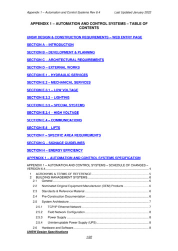
Appendix CProcess Flow Diagrams
Once Furnace HotStand-by/DecokingRecycled H2Quench TowerFreshEthaneFigure C-1: Ethane Cracker Process Flow DiagramFiveFurnacesNormalOperationsAcid GasCGCStages 1-4RemovalDryers &Chilling TrainCGCStage5thPressure SwingAdsorptionRecycled Tail GasReactorEthyleneStorageEthane Recycle to FurnacePropane Recycle to FurnaceC3SplitterC3 CutPropyleneStorageThermalOxidizerDepropanizerRaw C4StorageC4 CutDebutanizerEthane CrackerFlaresC2SplitterAcetyleneC2 CutDeethanizerDemethanizerSpent CausticSystemGasolineStorageC5 Product FeedsNatural Gas FeedsRecycle FeedsOxidizer FeedsFuel BurningEquipment
To AtmosphereTo AtmosphereTo AtmosphereTo AtmosphereTo AtmosphereTo EthaneEthaneEthaneFuel:Tail Gas NaturalGasFuel:Tail Gas NaturalGasFuel:Tail Gas NaturalGasFuel:Tail Gas NaturalGasFuel:Tail Gas NaturalGasFuel:Tail Gas NaturalGasEmission Unit:PyrolysisFurnace #1 EC-PF-101Emission Unit:PyrolysisFurnace #2 EC-PF-102Emission Unit:PyrolysisFurnace #3 EC-PF-103Emission Unit:PyrolysisFurnace #4 EC-PF-104Emission Unit:PyrolysisFurnace #5 EC-PF-105Emission Unit:PyrolysisFurnace #6 EC-PF-106EmissionControl: UltraLow NOxBurnersEmissionControl: UltraLow NOxBurnersEmissionControl: UltraLow NOxBurnersEmissionControl: UltraLow NOxBurnersEmissionControl: UltraLow NOxBurnersEmissionControl: UltraLow NOxBurnersFigure C-2: Ethane Cracker EmissionSourcesNotes:1. The Ethane Crackers ‘ fuel consists of a mixture of recycled tail gas (hydrogen rich) and natural gas(methane), with a heating value of 523 Btu/scf.2. Normal operation assumes five furnaces continuous operation and one furnace on hot stand-by ordecoking operations.
To AtmosphereDecoking EffluentSteam/Air MixtureEffluent sent tocombustionchamber (i.e.Firebox)Fuel:Tail Gas Natural GasFurnace Fried at30% Full LoadFigure C-3: Decoking OperationsNotes:1. Max decoking firing time for all six furnaces is 864 hours per year @ 30% normal load (119 MMBtu/hr)2. Decoking operations will occur a maximum of 12 events per year per furnace.
Figure C-4A: Polyethylene Plant A Process Flow PA-CA-101COMONOMERPOLYMERIZATIONETHYLENEPURGING AND VENTRECOVERYPA-PE-202EXTRUSION NProduct FeedsVent StreamsMAINFLAREEC-FL-101Recycle FeedsFlare FeedsFuel BurningEquipmentPM Pollution ControlDevicesPolyethylene
Figure C-4B: Polyethylene Plant B Process Flow G AND VENTRECOVERYEXTRUSION ROCARBONNITROGENPB-PE-303PB-PE-304NITROGENProduct FeedsVent StreamsLOWPRESSUREFLAREPB-FL-105Recycle FeedsFlare FeedsFuel BurningEquipmentPM PollutionControl Devices
Figure C-4C: Polyethylene Plant C Process Flow DiagramRECYCLED GAS TRANSPORTED TO C-PE-302PC-PE-303EXTRUSION &PELLETIZINGPELLETHANDLINGDEGASSING -202PC-PE-203ETHYLENEPC-PE-301Product FeedsVent StreamsRecycle FeedsWaste FeedsOxidizer FeedsREGENERATIVETHERMAL OXIZIZERPC-TO-102Fuel BurningEquipmentPM PollutionControl Devices
Fuel and WasteCombustion EmissionsFuel and WasteCombustion EmissionsWaste StreamsWaste StreamsEmission Unit:Cracker ProcessOxidizer EmissionsEC-CP-101Natural gasEmission Unit:Cracker ThermalOxidizerEC-TO-101Emission Controls:Low NOx BurnersFigure C-5: Cracker ThermalOxidizer and RTO Emission SourcesNatural gasEmission Unit: PEProcess - OxidizerEmissionsPC-TO-103Emission Unit:Regenerative ThermalOxidizerPC-TO-102Emission Controls: LowNOx BurnersNote:Each oxidizer has two emission sources associated with normal operation; (1) burner fuelcombustion and (2) oxidization waste combustion
To AtmosphereTo AtmosphereTo AtmosphereTo AtmosphereTo AtmosphereNatural gasNatural gasPressure ReliefStreamMain FlareEmission Unit:EC-FL-101Pressure ReliefStreamPressure ReliefStreamEthyleneStorage FlareEmission Unit:EC-FL-102Figure C-6: Flare Emission SourcesNatural gasCracker StorageFlareEmission Unit:EC-FL-103Natural gasPressure ReliefStreamNatural gasPressure ReliefStreamOxygen FlareEmission Unit:EC-FL-104Notes:Potential emissions from flares include natural gas pilot combustion and non-emergencypressure relief events.Low PressureFlareEmission Unit:PB-FL-105
Emission Unit: HRSGDuct Burner SU-GT102To AtmosphereEmission Controls:SCR and OxidationCatalystNG FuelHRSG Duct BurnerSteam TurbineNG FuelCompressorCombustionCombustionTurbineEmission Unit: Gas CombustionTurbine SU-GT-101Emission Controls: SCR andOxidation CatalystFigure C-7: CogenerationCombustion Turbine and HRSGEmission SourcesNotes:Combustion Turbine model number : GE 7EA
To AtmosphereTo AtmosphereMake-upCoolingWaterNatural gasNatural gasPM/PM10/PM2.5 andVOC fugitive emissionsto atmosphereEmission UnitAuxiliary Boiler #1SU-AB-101Emission UnitAuxiliary Boiler #2SU-AB-102Emission Unit: Cooling TowerSU-CT-101Emission Controls:ULNB & FGREmission Controls:ULNB & FGREmission Controls: Highefficiency Drift EliminatorFigure C-8: Auxiliary Boilers andCooing Tower Emission SourcesNotes:ULNB – Ultra Low NOx BurnersFGR – Flue Gas RecirculationPM – Particulate Matter
Figure C-9: Wastewater Treatment PlantProcess Flow DiagramOily WaterStorage TankDAFOily Water LiftStationCPIMixTankSludgeDewateringOily ProcessWastewaterOther ProcessWastewaterInfluentSludgePretreated Spent CausticFlare Hydraulic SealPE/Logistics EffluentsISBL EffluentsEQ TankAeration BasinSanitary WasteEffluent toRiverEmission PointsNotes:CPI – Chemical-Physical Treatment UnitDAF – Dissolved Air Flotation UnitMBBR - Membrane Biological ReactorEQ Tank - Equalization TankSanitary LiftStationMBBR
SU-EG-101SU-EG-105Cracker PlantEG - 2800 kWUtility #1 EG 2800 kWSU-EG-102PE Plant A EG 2800 kWSU-EG-103PE Plant C EG 2800 kWSU-EG-106Utility #2 EG 2800 kWSU-FP-101SU-EG-108Firewater Pump #1485 kWCooling WaterArea - 350 kWSU-EG-109Product Storage350 kWSU-FP-102Firewater Pump #2485 kWSU-EG-107WWTP EG 2800 kWSU-FP-103Firewater Pump #3485 kWSU-EG-104Emission UnitPE Plant B EG 2800 kWULSD FuelEmission Pointto atmosphereFigure C-10: Internal CombustionEngine Emission SourcesNotes:EG – Emergency GeneratorFP – Firewater PumpPE - PolyethyleneWWTP – Wastewater Treatment Plant
EC-FL-101 Figure C-4A: Polyethylene Plant A Process Flow Diagram Product Feeds Vent Streams Recycle Feeds Flare Feeds Fuel Burning Equipment PM Pollution Control Devices POLYMERIZATION PA-PE-202 PURGING AND VENT RECOVERY PA-PE-203 EXTRUSION & PELLETIZING PA-PE-204 ETHYLENE INERT HYDROCARBON NITROGEN Polyethylene HYDROGEN NITROGEN PA-PE-301 PA .