Transcription
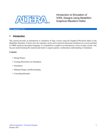
EE 108 – Digital systems IWinter 2002-2003Modelsim TutorialTutorialModelSim SEA.Creating a ProjectThe goals for this lesson are:- Create a projectA project is a collection entity for an HDL design under specification or test. Projects ease interactionwith the tool and are useful for organizing files and simulation settings. At a minimum, projects have awork library and a session state that is stored in a .mpf file. A project may also consist of:o HDL source files or references to source fileso other files such as READMEs or other project documentationo local librarieso references to global librariesFor more information about using project files, see the ModelSim User’s Manual.1.Start ModelSim:from a Windows shortcut icon, from the Start menuUpon opening ModelSim for the first time, you will see the Welcome to ModelSim dialog. (If thisscreen is not available, you can display it by selecting Help WelcomeMenu from the Main window.)2.Select Create a Projectfrom the Welcome dialog, or File New Project (Main window). In the Create Project dialog box,enter "test" as the Project Name and select a directory where the project file will be stored. Leave theDefault Library Name set to "work."Upon selecting OK, you will see a blank Project tab in the workspace area of the Main window andthe Add Items to the Project dialog.Page 1 sur 14
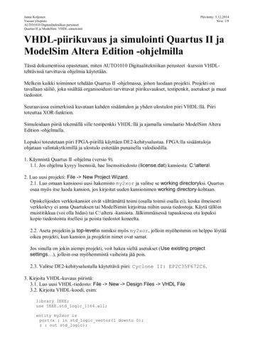
EE 108 – Digital systems IWinter 2002-20033.Modelsim TutorialThe next step is to add the files that contain your design units.Click Add Existing File in the Add Items to Project dialog. For this exercise, we’ll add two Verilogfiles. Click the Browse button in the Add file to Project dialog box and open the examples directory inyour ModelSim installation. Select tcounter.v and counter. v. Select Reference from current locationand then click OK.4.Click your right mouse buttonin the Project page and select Compile Compile All.Page 2 sur 14
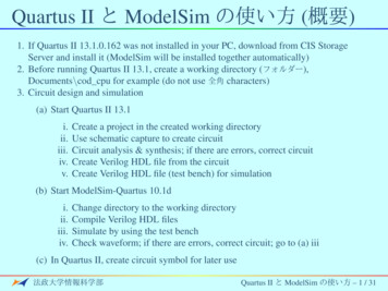
EE 108 – Digital systems IWinter 2002-20035.Modelsim TutorialThe two files are compiled.Click on the Library tab and expand the work library by clicking the " " icon. You’ll see the compileddesign units listed.6.Load one of the design unitsThe last step in this exercise is to load one of the design units. Double-click counter on the Librarypage. You’ll see a new page appear in the Workspace that displays the structure of the counter designunit.Page 3 sur 14
EE 108 – Digital systems IWinter 2002-2003Modelsim TutorialAt this point, you would generally run the simulation and analyze or debug your design. We’ll do justthat in the upcoming lessons. For now, let’s wrap up by ending the simulation and closing the project.Select Simulate End Simulation and confirm that you want to quit simulating. Next, select File Close Project, confirm that you want to close the project, and select Yes to update your project filewith the changes you made during this session.Note that a test.mpf file has been created in your working directory. This file contains informationabout the project test that you just created. ModelSim will open this project automatically the nexttime you invoke the tool.Page 4 sur 14
EE 108 – Digital systems IWinter 2002-2003B.Modelsim TutorialBasic Verilog simulationThe goals for this lesson are:- Compile a Verilog design- List signals in the design- Examine the hierarchy of the design- Simulate the design- Change the default run length- Set a breakpointThe project feature covered in A executes several actions automatically such as creating and mappingwork libraries. In this part we will go through the entire process so you get a feel for how ModelSimreally works.1.Compiling the designa)Create and change to a new directory to make it the current directory.You can make the directory current by invoking ModelSim from the new directory or by using theFile Change Directory command from the ModelSim Main window.b)Copy the Verilog files (files with ".v" extension)from the \ install dir \modeltech\examples directory into the current directory.Before you can compile a Verilog design, you need to create a design library in the new directory.Since ModelSim is a compiled Verilog simulator, it requires a target design library for thecompilation. ModelSim can compile both VHDL and Verilog code into the same library if desired.c)Invoke ModelSim:from a Windows shortcut icon, from the Start menuClick Close if the Welcome dialog appears.d)Create libraryBefore you compile any HDL code, you’ll need a design library to hold the compilation results. Tocreate a new design library, make this menu selection in the Main window: File New Library.Make sure Create: a new library and a logical mapping to it is selected.Type "work" in the Library Name field and then select OK. This creates a subdirectory named work your design library - within the current directory. ModelSim saves a special file named info in thesubdirectory.(PROMPT: vlib work vmap work work)Page 5 sur 14
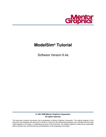
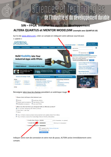
EE 108 – Digital systems IWinter 2002-2003Modelsim TutorialIn the next step you’ll compile the Verilog design. The example design consists of two Verilog sourcefiles, each containing a unique module. The file counter.v contains a module called counter, whichimplements a simple 8-bit binary up-counter. The other file, tcounter. v, is a testbench module(test counter) used to verify counter.Under simulation you will see that these two files are configured hierarchically with a single instance(instance name du t) of module counter instantiated by the testbench.You'll get a chance to look at the structure of this code later. For now, you need to compile both filesinto the work design library.Note: Do not create a Library directory using Windows commands, becausethe info file will not be created. Always use the File menu or the vlib command fromeither the ModelSim or UNIX/DOS prompt.)e)CompileCompile the counter.v, and tcounter.v files into the work library by selecting Compile Compilefrom the menu.(PROMPT: vlog counter.v tcounter.v)This opens the Compile HDL Source Files dialog box.Select counter.v and tcounter.v (use Ctrl click) and then choose Compile and then Don e.Page 6 sur 14
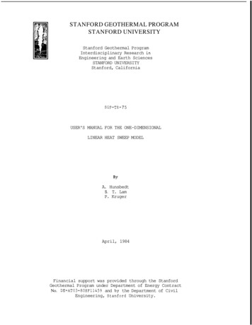
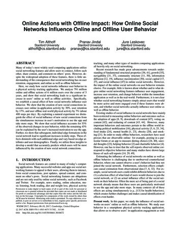
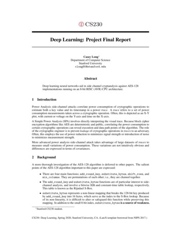
EE 108 – Digital systems IWinter 2002-2003Modelsim TutorialNote: The order in which you compile the two Verilog modules is not important (other than thesource-code depende ncies created by compiler directives). So it doesn’t matter here if you choose tocompile counter.v before or after tcounter. v.2.Loading the designa)Load the designby selecting Simulate Simulate from the menu:(PROMPT: vsim test counter)The Simulate dialog appears. Click the " " sign next to ’work’ to see the counter and test counterdesign units. (You won’t see this dialog box if you invoke vsim with test counter from the commandline.)The Simulate dialog allows you to select a design unit to load from the specified library. You can alsoselect the resolution limit for the simulation. The default resolution is 1 ns.Select test counter and click Load to accept these settings.b)Bring up the Signals, Source, and Wave windowsby entering the following command at the VSIM prompt within the Main window : view signalssource wave(Main MENU: View window name )c)Add signalsNow let’s add signals to the Wave window with ModelSim’s drag and drop feature. In the Signalswindow, select Edit Select All to select the three signals. Drag the signals to either the pathname orthe values pane of the Wave window.Page 7 sur 14
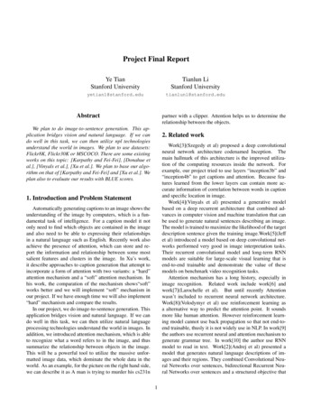
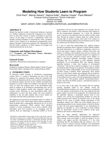
EE 108 – Digital systems IWinter 2002-2003Modelsim TutorialHDL items can also be copied from one window to another (or within the Wave and List windows)with the Edit Copy and Edit Paste menu selections.d)Structure paneYou may have noticed when you loaded the design in Step 1 that a new tab appeared in the workspacearea of the Main window.The Structure tab shows the hierarchical structure of the design. By default, only the top level of thehierarchy is expanded. You can navigate within the hierarchy by clicking on any line with a " "Page 8 sur 14
EE 108 – Digital systems IWinter 2002-2003Modelsim Tutorial(expand) or "-" (contract) symbol. The same navigation technique works anywhere you find thesesymbols within ModelSim.By clicking the " " next to dut: counter you can see all three hierarchical levels: test counter,counter and a function called increment. (If test counter is not displayed you simulated counterinstead of test counter.)Click on Function increment and notice how other ModelSim windows are automatically updated asappropriate. Specifically, the Source window displays the Verilog code at the hierarchical level youselected in the Structure window, and the Signals window displays the appropriate signals. Using theStructure tab in this way is analogous to scoping commands in interpreted Verilogs.For now, make sure the test counter module is showing in the Source window by clicking on the topline in the Structure pane.3.Running the simulationNow you will exercise different Run functions from the toolbar.a)RunSelect the Run button on the Main window toolbar. This causes the simulation to run and then stopafter 100 ns (the default simulation length).(PROMPT: run) (MENU: Simulate Run Run 100 ns)b)Specify run lengthNext change the run length to 500 on the Run Length selector and select the Run button again.Now the simulation has run for a total of 600ns (the default 100ns plus the 500 you just asked for).The status bar at the bottom of the Main window displays this information.c)Run until specified timeThe last command you executed (run 500) caused the simulation to advance for 500ns. You can alsoadvance simulation to a specific time. Type: run @ 3000This advances the simulation to time 3000ns. Note that the simulation actually ran for an additional2400ns (3000 - 600).Page 9 sur 14
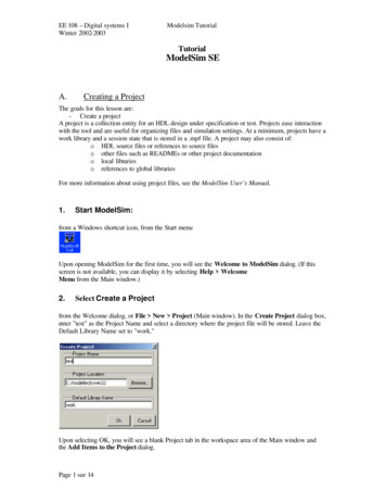
EE 108 – Digital systems IWinter 2002-2003d)Modelsim TutorialRun until breakpointNow select the Run -All button from the Main window toolbar. This causes thesimulator to run until the stop statement in tcounter.v.(PROMPT: run -all) (MENU: Simulate Run Run -All)You can also use the Break button to interrupt a run.(MENU: Simulate Break)4.DebuggingNext we’ll take a brief look at an interactive debugging feature of the ModelSim environment.a)Set a breakpointLet’s set a breakpoint at line 30 in the counter.v file (which contains a call to the Verilog functionincrement). To do this, select dut: counter in the Structure pane of the Workspace. Move the cursor tothe Source window and scroll the window to display line 30. Click on or near line number 30 to set abreakpoint. You should see a red dot next to the line number where the breakpoint is set.The breakpoint can be toggled between enabled and disabled by clicking it. When a breakpoint isdisabled, the dot appears open. To delete the breakpoint, click the line number with your right mousebutton and select Remove Breakpoint.b)RestartSelect the Restart button to reload the design elements and reset the simulation time to zero.(Main MENU: Simulate Run Restart) (PROMPT: restart)Page 10 sur 14
EE 108 – Digital systems IWinter 2002-2003Modelsim TutorialNote: Breakpoints can be set only on executable lines, denoted by blue line numbers.Make sure all items in the Restart dialog box are selected, then click Restart.Select the Run -All button to re-start the simulation run.(PROMPT: run -all) (Main MENU: Simulate Run Run -All)When the simulation hits the breakpoint, it stops running, highlights the line with an arrow in theSource window, and issues a Break message in the Main window.c)Reading signal valuesWhen a breakpoint is reached, typically you will want to know one or more signal values. You haveseveral options for checking values :- look at the values shown in the Signals window- hover your mouse pointer over the count variable in the Source window and a "balloon" willpop up with the valuePage 11 sur 14
EE 108 – Digital systems IWinter 2002-2003-Modelsim Tutorialselect the count variable in the Source window, right-click it, and select Examine from thecontext menuuse the examine command to output the value to the Main window transcript: examine countd)StepLet’s move through the Verilog source functions with ModelSim’s Step command.Click Step on the toolbar.This command single-steps the debugger.e)Hands-onExperiment by yourself for awhile. Set and clear breakpoints and use the Step and Step Overcommands until you feel comfortable with their operation. When you’re done, quit the simulator byentering the command: quit –forceC.Exhaustive simulation using verilog1.Test bench for the counter moduleAs you have seen, along with the actual module is another Verilog file, called a test bench forthis module. This module creates the test vector that enables us to check that the programactually performs the right function.In this example, the test bench is pretty short, since the only input is the clock, but othersystems might have more inputs and you might want to simulate all possible realizations ofthese inputs. (For example, for a 3-to8 decoder, you want to generate all possible 3 bit inputs)StimulusPage 12 sur 14SystemunderVerificationResultsAnalysis
EE 108 – Digital systems IWinter 2002-2003Modelsim TutorialWe will now analyse the structure of the program to understand the different ------------------------------------module test counter;reg clk, rst;wire [7:0] count;Regular module declaration : there is no inputs nor ----------------------------------In th is code fragment, the stimulus and response capture are going to be coded usinga couple of initial blocks. An initial block can contain sequential statements that canbe used to describe the behaviour of signals in a test bench. In the Stimulus initialblock, we need to generate waveforms on the clock and reset inputs. Thus:initial // Clock generatorbeginclk 0;#10 forever #10 clk !clk;endinitial // Test stimulusbeginrst 0;#5 rst 1;#4 rst 0;#50000 stop;endEverytime there is a pound sign followed by a number n, it means that the simulatoradvances by n times of simulation and then does whatever assignment is specified.The stop command is a Verilog built-in command that stops the simulation. In thiscase, the simulation will stop after 50009 simulation times.Concerning the clock, its behavior is easy to understand. At the beginning, its value isset to zero ; then, every 10 seconds and for ever, its value is ------------------------------------counter#(5,10) dut (count,clk,rst);The test bench has to instantiate an instance of the module -----------------------------------initialPage 13 sur 14
EE 108 – Digital systems IWinter 2002-2003Modelsim Tutorial monitor( stime,, rst,, clk,,, count);The Response initial block can be described very easily in Verilog as we can benefitfrom a built-in Verilog system task. Indeed, monitor is a system task that is part ofthe Verilog language. Its mission in life is to print values to the screen. The values itprints are those corresponding to the arguments that you pass to the task when it isexecuted. The monitor task is executed whenever any one of its arguments changes,with one or two notable exceptions : time is a system function (as opposed to a system task). It returns the currentsimulation time. In the above example, time is an argument to monitor. However, time changing does not cause monitor to execute — monitor is clever enough toknow that you wouldn't really want to print to the screen the values of all of thearguments every time the simulation time changed.The succession of two commas in the argument list ensures that a space is printed tothe screen after the value of time each time monitor is executed. This is a simplemethod of formatting the screen output.Finally we come to the signal arguments themselves. Each time one of these signalschanges value, monitor will execute. When monitor executes it will print all of theargument values to the screen, including time. This is the output created by monitorin our counter test bench:################00051090015 0 020 0 125 0 130 0 040 0 145 0 150 0 060 0 165 0 170 0 080 0 185 0 190 0 0xxx0011122233344endmoduleA last note on this test bench ; to access and monitor a signal which is in a lower hierarchicallevel, you just have to call the signal by the module name, followed by a dot, followed by thesignal name.Page 14 sur 14
a) Load the design by selecting Simulate Simulate from the menu: (PROMPT: vsim test_counter) The Simulate dialog appears. Click the " " sign next to 'work' to see the counter and test_counter design units. (You won't see this dialog box if you invoke vsim with test_counter from the command line.)