Transcription
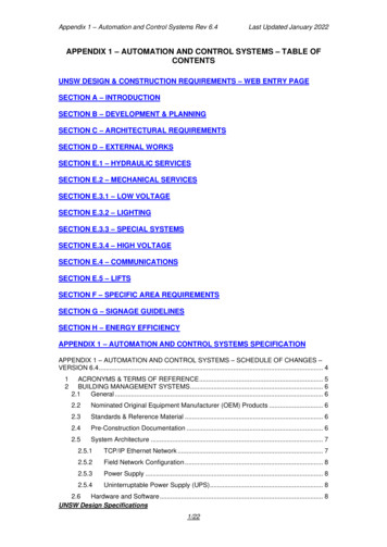
Appendix 1 – Automation and Control Systems Rev 6.4Last Updated January 2022APPENDIX 1 – AUTOMATION AND CONTROL SYSTEMS – TABLE OFCONTENTSUNSW DESIGN & CONSTRUCTION REQUIREMENTS – WEB ENTRY PAGESECTION A – INTRODUCTIONSECTION B – DEVELOPMENT & PLANNINGSECTION C – ARCHITECTURAL REQUIREMENTSSECTION D – EXTERNAL WORKSSECTION E.1 – HYDRAULIC SERVICESSECTION E.2 – MECHANICAL SERVICESSECTION E.3.1 – LOW VOLTAGESECTION E.3.2 – LIGHTINGSECTION E.3.3 – SPECIAL SYSTEMSSECTION E.3.4 – HIGH VOLTAGESECTION E.4 – COMMUNICATIONSSECTION E.5 – LIFTSSECTION F – SPECIFIC AREA REQUIREMENTSSECTION G – SIGNAGE GUIDELINESSECTION H – ENERGY EFFICIENCYAPPENDIX 1 – AUTOMATION AND CONTROL SYSTEMS SPECIFICATIONAPPENDIX 1 – AUTOMATION AND CONTROL SYSTEMS – SCHEDULE OF CHANGES –VERSION 6.4 . 412ACRONYMS & TERMS OF REFERENCE . 5BUILDING MANAGEMENT SYSTEMS . 62.1General . 62.2Nominated Original Equipment Manufacturer (OEM) Products . 62.3Standards & Reference Material . 62.4Pre-Construction Documentation . 62.5System Architecture . 72.5.1TCP/IP Ethernet Network . 72.5.2Field Network Configuration . 82.5.3Power Supply . 82.5.4Uninterruptable Power Supply (UPS) . 82.6Hardware and Software . 8UNSW Design Specifications1/22
Appendix 1 – Automation and Control Systems Rev 6.4Last Updated January 20222.6.1Engineering Code/DDC . 82.6.2System Passwords . 82.7BACnet Configuration and Naming Convention . 92.7.1BMS Hardware . 92.7.2Point Database . 92.7.3Trend-logs . 92.7.4Time Schedules . 92.7.5Alarms . 92.8Alarm Management . 102.8.1CAMS Alarm Configuration . 102.8.2Critical Plant and Infrastructure (CPI) Alarms . 102.8.3Life Safety System (LSS) and Gas Detection Alarms . 112.8.4Critical User Equipment (CUE) Alarms . 112.8.5BMS Health Alarm Management . 122.8.6Analytics/FDD Alert Management . 122.9Integrated Components & Sub-System Interfaces . 122.9.1Bulk Tank Storage . 122.9.2Building Electrical Systems . 122.9.3Essential Services Circuit Breaker Monitoring . 122.9.4Thermal Energy Meters . 122.9.5MCC Electrical Energy Meters . 122.9.6Utilities Metering (EMACS). 132.9.7Fire Systems . 132.9.8Fume Cupboards . 132.9.9Generators . 132.9.10Heating Ventilation & Air Conditioning Plant . 132.9.11Hydraulic Systems . 132.9.12IAQ Sensors . 132.9.13IoT Sensors . 132.9.14Laboratory Air Management Systems . 132.9.15Life Safety Systems (LSS) & Gas Detection Systems . 132.9.16Lift Systems . 142.9.17Lighting Systems - Internal . 142.9.18Lighting Systems - External. 142.9.19Uninterruptable Power Supplies (UPS) . 142.9.20VRV/VRF DX Air Conditioning Systems . 142.10Control System Functionality . 142.10.1Actuator Position Monitoring . 142.10.2Automatic Lockout Resets. 142.10.3Cooling and Heating Plant Staging Strategies . 14UNSW Design Specifications2/22
Appendix 1 – Automation and Control Systems Rev 6.42.10.4Global Override Modes - Zone Temperature Set Point Adjustment . 142.10.5Global Override Modes – Chilled & Hot Water Valves . 152.10.6Maintenance Mode – Main Plant . 152.10.7Manual Staging Control . 152.10.8Occupancy & After-Hours Air Conditioning (AHAC) . 152.10.9Rogue Zone De-Selection - Building Cooling/Heating Call . 152.10.10Rogue Zone De-Selection – Air Side Plant Demand . 152.10.11Supply Air Temperature Monitoring . 152.10.12Setpoint Reset Strategies . 152.11Graphical Standards . 152.12Change Management Procedures . 162.13Commissioning . 162.13.0Acceptance Testing (FAT and SAT) . 162.13.1Integrated Systems Testing (IST) . 162.13.2Practical Completion . 172.143Last Updated January 2022Documentation . 17LIFE SAFETY SYSTEM . 183.1General . 183.2Standards and Reference Material . 183.3System Architecture . 183.3.1Network Architecture . 193.3.2LSS Components . 193.3.3Mean Time To Repair (MTTR) . 193.3.4LSS Control Panel HMI . 193.3.5Audible Alarms . 193.3.6Visual Alarms . 193.3.7Emergency Stops . 193.3.8LSS HLI . 203.3.9Field Devices for Safety Functions . 203.3.10Power . 203.3.11Uninterruptable Power Supply (UPS) . 203.3.12Oxygen and Gas Sensors . 203.4Operator Interface Hardware and Software . 203.4.1Engineering Code . 203.4.2System Passwords . 203.5Point Database . 203.6Change Management Procedures . 213.7Integrated Systems . 213.7.1Fire Trip . 213.7.2Fan Failure . 21UNSW Design Specifications3/22
Appendix 1 – Automation and Control Systems Rev 6.43.7.33.8Last Updated January 2022BMS . 21Commissioning . 213.8.1Commissioning and Programming . 213.8.2Practical Completion . 213.8.3Acceptance Testing . 223.8.4Integrated Systems Testing (IST) . 223.9Documentation . 223.9.1Pre-Construction Design Documentation . 223.9.2As-Built Documentation . 22APPENDIX 2 – CONCRETE FOR STRUCTURESAPPENDIX 4 – DOCUMENT REQUIREMENTSAPPENDIX 5 – UNSW STANDARD PRELIMINARIESAPPENDIX 6 – SECURITY SYSTEMSAPPENDIX 7 – UNSW ENERGY MANAGEMENT METERING REQUIREMENTSAPPENDIX 8 – UNSW ROOM NUMBERING STANDARDSAPPENDIX 9 – UNSW STORMWATER MASTERPLAN STRATEGY - 2025APPENDIX 1 – AUTOMATION AND CONTROL SYSTEMS – SCHEDULE OFCHANGES – VERSION 6.4As a guide only, attention is drawn to changes that have been made in the following clausessince the last revisionRevisionChangesDateGeneral revisionNo changesAugust 20044.1Major rewriteJuly 20054.2General revisionSeptember 2013Major rewriteJuly 20155.1General revisionApril 20165.2General revisionMarch 2017Major rewriteMarch 20186.1Critical alarm section updatedApril 20196.2Major rewrite, 2.9 GraphicalStandards added, 2.8 CAMSAlarm Matrix addedSeptember 20196.3Minor rewritesJanuary 20206.4Minor updatesJanuary 202256UNSW Design Specifications4/22
Appendix 1 – Automation and Control Systems Rev 6.4Last Updated January 20221 ACRONYMS & TERMS OF REFERENCEBACnetBMS communication protocolBMSBuilding Management SystemBTLBACnet Testing LaboratoriesCardaxAccess Control and Security SystemCBACSCampus Building Automation and Control SystemCAMSCritical Alarm Management SystemCPICritical Plant and InfrastructureCUECritical User Equipment – School or Faculty Fridges/Freezers/IncubatorsEM EngineeringUNSW Estate Management EngineeringFATFactory Acceptance TestFDDFault Detection DiagnosticsHAZIDHazard IdentificationHAZOPHazard and OperabilityHLIHigh Level InterfaceHMIHuman Machine InterfaceI/OInput / Output – Field monitoring and control devicesIoTInternet of ThingsIAQIndoor Air QualityISTIntegrated System TestLLILow Level InterfaceLSSLife Safety System and Gas DetectionModbusIndustry communication protocolMS/TPMaster Slave / Token Pass – BACnet communication protocolMTTRMean Time To RepairNASNetwork Attached StorageOEMOriginal Equipment ManufacturerO&MOperation and MaintenancePLCProgrammable Logic ControllerSATSite Acceptance TestSIFSafety Instrument FunctionTCP/IPNetwork ProtocolVLANVirtual Local Area NetworkUNSW Design Specifications5/22
Appendix 1 – Automation and Control Systems Rev 6.4Last Updated January 20222 BUILDING MANAGEMENT SYSTEMS2.1 GeneralThe works shall include design, supply, installation, and commissioning of nominated controlsystems to achieve the performance specified in the following clauses hereafter referred to asBMS. All BMS infrastructure shall be connected directly the CBACS VLAN using UNSWsupplied data ports and shall conform to the ASHRAE Standard 135-2020 BACnet protocolusing BACnet compliant BTL listed hardware and software to meet the system’s functionalspecifications. The integrated multivendor BMS network and associated interconnectedcampus, facility and building systems shall be referred to in the following document hereafteras CBACS.2.2 Nominated Original Equipment Manufacturer (OEM) ProductsOnly the following nominated OEM products and local distributors shall be used for capitalconstruction works: WebCTRL – Logical Building Automation Pty Ltd StruxureWare – Schneider Electric Buildings Australia Pty Ltd Enterprise Buildings Integrator (EBI) - Honeywell Building SolutionsWhere BMS infrastructure is being implemented in an existing building or facility it is essentialEM Engineering is engaged for OEM products proposed to ensure the integrity of incumbentsystem within existing buildings is maintained.2.3 Standards & Reference MaterialThe BMS shall be installed complying with all: National and local statutory regulations. Occupational Health & Safety legislation and codes of practice. SAA Wiring Regulations (AS3000). Building Code of Australia. OEM instructions and recommendations. ASHRAE Standard 135 BACnet.2.4 Pre-Construction DocumentationBMS Pre-Construction documentation shall be submitted for approval by EM Engineeringdetailing: Project Functional Descriptiono As-Built Building Functional Description shall be graphically available fromthe incumbent BMS web interface.o Improvement, extension or fit out projects Function Descriptions may besubmitted for approval separate to the As Built Building FunctionalDescription, however, must be included in the As Built Building FunctionalDescription documentation set at the completion of the project. Project BMS Network Schematic and Asset registero Network Schematic shall be graphically available from the incumbent BMSweb interface.o Improvement, extension or fit out projects Network Schematics shall besubmitted for approval as part of the complete As Built Network Schematicdocumentation set.o Network Schematics shall include detail of IP Ethernet Network, IPaddresses, BACnet instances MS/TP and VLAN number settings.UNSW Design Specifications6/22
Appendix 1 – Automation and Control Systems Rev 6.4oLast Updated January 2022Asset Register shall be submitted for approval with the Network Schematicdetailing IP addresses, BACnet instances MS/TP and VLAN number settingscontroller numbering, MAC address, model, configuration settings anddetails, passwords, locations and general information. Project BMS Network Asset Registero Network Asset Register shall be submitted for approval for each project.o Asset Register shall be submitted for approval detailing building, controllerlocation, numbering, MAC address, model, configuration settings and details,passwords and general information. EM approved Asset Registers shall detailIP addresses and VLAN configuration settings, BACnet device instanceranges and MS/TP numbering. Project BMS Points Listo As Built Points List shall be graphically available from the incumbent BMSweb interface.o Improvement, extension or fit out projects Built Points List may be submittedfor approval separate to the As Built BMS Points List, however, must beincluded in the As Built Building Built BMS Points List documentation set atthe completion of the project.2.5 System ArchitectureThe system architecture shall comprise of the required hardware and software components,networked together to provide a system of connected devices that operate as a single BMSfor the entire project, and integrate without adverse effect to the CBACS.All BMS Hardware and Software provided shall be BACnet compliant BTL listed andcommunicate using the protocols and network standards as defined by ANSI/ASHRAEStandard 135, a shall be installed to the OEM and BACnet standard.All materials and products used shall be new and current generation OEM productscommercially available for a minimum of five years after project completion. Untestedproducts shall not be used, unless explicitly approved by the EM Engineering in writing.2.5.1TCP/IP Ethernet NetworkDedicated BMS TCP/IP Ethernet Network and associated managed devices shall be providedby the incumbent contractor connecting all BMS and subsystem hardware at the building levelenabling communication and function as a stand-alone system. Device numbers on a networkor subnet shall be the lesser of that determined by the by the OEM standards, or the numberof devices that will not impact or degrade overall system performance. TCP/IP EthernetNetwork speeds shall be set to operate at the maximum speed specified by the OEMdocumentation and that determined by connected equipment. All dedicated TCP/IP EthernetNetwork cabling shall be Cat 6 and Yellow in colour.Network configuration including IP Addresses, Subnets, UDP/IP Port Number, MS/TPNetwork Number, Network Number and Device Instances will be supplied by EM Engineeringupon approval of the initial BMS network schematic or topology.The dedicated BMS TCP/IP Ethernet Network will be connected to the CBACS network andnominated VLAN via ethernet data ports provided by the University IT Unit.NOTE: It shall be the responsibility of contractors to ensure that the BMS designinterconnects with CBACS and the University IT network to achieve full system functionality,without impact to other BMS and CBACS infrastructure. The initial BMS network topology orschematic is required for approval by EM Engineering prior to project commencement.UNSW Design Specifications7/22
Appendix 1 – Automation and Control Systems Rev 6.42.5.2Last Updated January 2022Field Network ConfigurationField Network MS/TP, Modbus RTU, and approved others shall be wired in a daisy chainconfiguration only. Device numbers on a subnet shall be the lesser of that determined by theby the OEM standards, or the number of devices that will not impact or degrade overallsystem. Star or tee connections are not permitted unless recommended by the OEM. FieldNetwork speeds shall be set to operate at the maximum speed specified by the OEMdocumentation and that determined by connected equipment. All MS/TP and Modbus RTUcommunication cables shall be Yellow in colour.NOTE: Field Controllers, and HLI devices shall have separate dedicated MS/TP networks;mixed Field networks are not acceptable. Critical Plant and Infrastructure, User Equipmentand HLI devices shall have dedicated MS/TP and power segmented from other non-criticaldevices. The initial BMS network architecture or topology is required for approval by EMEngineering prior to project commencement.2.5.3Power SupplyAll power for BMS equipment shall be from dedicated circuits. BMS installations shall be fedfrom Essential Services supply with Generator back-up (where applicable). All VoltageTransformers shall be located within dedicated control enclosures. Separate VoltageTransformers shall be used for each BACnet Network Segment. I/O field peripherals andcontrol peripherals shall be separately powered from the BACnet Network Segments. Powershall not be obtained by tapping into miscellaneous circuits that could be inadvertentlyswitched off.2.5.4Uninterruptable Power Supply (UPS)BMS installations shall be installed with APC Smart-UPS (or approved equivalent) locatedwithin or adjacent to the designated control enclosure to supply power to all components ifcentralised building UPS is provided. UPS shall be monitored to indicate fault condition andalarmed on the BMS. UPS shall be installed with a bypass switch for maintenance andreplacement purposes.2.6 Hardware and SoftwareHardware and software shall be on existing CBACS Servers provided by UNSW built to theOEM’s minimum requirements.All BMS hardware and software is to be BACnet compliant, BTL listed, and configured to currentUNSW naming conventions in-line with the UNSW building grid references. IP addresses,subnet configuration, device instances, network numbers, port numbers etc. shall be suppliedpending initial Pre-Construction Documentation approval by EM Engineering (refer to Section2.4). All operating software including but not limited to system software, licenses, administrationlevel passwords, drivers, registration details, backups etc. shall be submitted to EM Engineeringon approved media. Backup copies of software and documentation shall be made and savedto the UNSW provided CBACS NAS. Operator Interface Software shall be on existing CBACSServers provided by UNSW which are remotely accessible, and on a mobile platform as suchterminal PC’s and physical user interfaces are not required unless otherwise specified.2.6.1Engineering Code/DDCSoftware tools required to access, review and/or edit DDC/Engineering code for all installedequipment shall be provided and installed on CBACS Servers and/or Workstations.2.6.2System PasswordsAdministration level passwords for Operating Systems shall be provided and detailed as partof the As Built documentation. Default hardware System, Application Controller, and HLIhardware configuration passwords shall be changed to passwords allocated by EM Engineeringrequired to access, review and/or edit DDC/Engineering.UNSW Design Specifications8/22
Appendix 1 – Automation and Control Systems Rev 6.4Last Updated January 20222.7 BACnet Configuration and Naming Convention2.7.1BMS HardwareBMS hardware naming descriptions are to be pre-fixed with the UNSW building grid reference,followed by the item location room code, followed by the function/plant served. Example:D26 8Q05 Chilled Water Plant Control Building Pre-fix: D26 Room Code: 8Q05 Plant/Component: Chilled Water Plant Control2.7.2Point DatabasePhysical I/O and software point database naming descriptions are to be pre-fixed with theUNSW building grid reference, followed by the item location room code, followed by theplant/component type, and point description. All hardware and software points are to have pointnames descriptive of the associated equipment or software point to form the point database.Example: D26 603 Lab 221 Exhaust Fan 3.2 Enable Building Pre-fix: D26Room Code: 603Plant/Component: Lab 221Description: Exhaust Fan 3.2State: EnableNOTE: Points Lists must be submitted for approval by EM Engineering prior to projectcommencement.2.7.3Trend-logsTrend-logs are to be set up on all general system inputs, variable set points at a fifteen (15)minute period, with operational outputs trended on Change Of Value (COV) for 12 months,after which time the trend data shall be archived to the appropriate Server. Critical systemtrend-logs are to be set up on all system inputs, variable set points, and binary and variableoutputs at a five (5) minute period for 12 months, after which time the trend data shall bearchived to the appropriate Server. Trend-Log point description shall be in-line with the PointDatabase (1.12) naming convention.2.7.4Time SchedulesUpon initial setup, the following schedules shall be programmed for each facility, withseparate scheduling for each floor, area and plant. Building Prefix Normal Schedule:8:00am – 6:00pm Building Prefix Extended Schedule 1:8:00am – 9:00pm Building Prefix Extended Schedule 2:7:00am – 10:00pm Building Prefix Cooling/Heating Plant Lockout Schedule:9:00pm – 7:00am Building Prefix Critical Schedule:24 hoursAdditional Time Schedules shall have point names descriptive of the associated equipment,device, or software point, to form the point database. Time Schedule descriptions are to be prefixed with the UNSW building grid reference, followed by the plant/component type. TimeSchedule point description shall be in-line with the Point Database (1.12) naming convention.2.7.5AlarmsAlarms are to be categorised and configured as per section 2.8. All alarms shall be BACnetcompliant and exposed to the relevant network.UNSW Design Specifications9/22
Appendix 1 – Automation and Control Systems Rev 6.4Last Updated January 20222.8 Alarm ManagementUNSW’s Alarm Management is structured to separate operational and critical events. Allalarms shall be categorised and configured as per the Alarm Matrix (below). All alarms shallbe BACnet alarms. Alarm names shall not be abbreviated. Alarm descriptions are to be prefixed with the UNSW building grid reference, followed by the room code, followed by theplant/component type, alarm description, and fault type. All alarms are to have point namesdescriptive of the associated equipment or software point. Alarm/Fault/Alert point descriptionshall be in-line with the alarm type naming convention.Alarm MatrixAlarm TypeEquipment itical Plant &Infrastructure(CPI)Central Plant FailureCentral Plant Water TemperatureCentral Plant Water PressureCritical Space Temperature/HumidityCritical Space PressureCritical Space VentilationProcess Plant FailureProcess Plant Water TemperatureProcess Plant Water PressureFlood DetectionFume CupboardElectrical FailureGenerator OperationUPS FailureFire TripToxic Gas DetectionOxygen DepletionEmergency Stop/ShutdownSecurity ControlBuilding ManagementEM ContractorsResearch Staff (uponrequest)CAMS24/7Security ControlResearch StaffBuilding ManagementEM ContractorsCAMS24/7FridgesFreezersIncubatorsCool RoomsCryo StorageBMS Comms/Power FailureSecurity ControlFaculty On-Call PhoneResearch StaffCAMS6pm-6am Mon-Fri24/7 Weekendsand PublicHolidaysSecurity ControlEM ContractorsEM EngineeringCAMS24/7HVAC OperationBuilding Services OperationCritical Spaces OperationEM EngineeringBuilding ManagementBMS24/7Critical LifeSafety Systems(LSS)Critical UserEquipment(CUE)BMS HealthAnalytics/FDD2.8.1CAMS Alarm ConfigurationCritical Alarm Management System - CAMS is an enterprise layer of integrated systems thatprovides alarm response for UNSW operations and first responders. Critical alarms shall bedisplayed on a graphical interface for integration with CAMS. Software isolation shall beprogrammed and represented via a graphical alarm summary per building.CAMS Alarms shall be categorised in three groups for each BMS installation: CPI – Critical Plant and Infrastructure LSS – Life Safety Systems CUE – Critical User Equipment (Schneider StruxureWare product only)2.8.2Critical Plant and Infrastructure (CPI) AlarmsCPI refers to monitoring of HVAC systems, mechanical systems, electrical systems, hydraulicsystems, process systems, fire systems, laboratory exhaust, fume cupboards, generators andintegrated building systems associated with Critical Plant. Hardwired monitoring points shall beUNSW Design Specifications10/22
Appendix 1 – Automation and Control Systems Rev 6.4Last Updated January 2022wired in a fail-safe configuration, where in the event of power failure alarms will be sent. CAMSalarms shall not be abbreviated. CAMS alarm descriptions are to be in-line with pre-fixed withthe UNSW building grid reference, followed by the plant/component type, alarm description,and fault type. CPI alarms shall
appendix 4 - document requirements appendix 5 - unsw standard preliminaries appendix 6 - security systems appendix 7 - unsw energy management metering requirements appendix 8 - unsw room numbering standards appendix 9 - unsw stormwater masterplan strategy - 2025 appendix 1 - automation and control systems - schedule of