Transcription
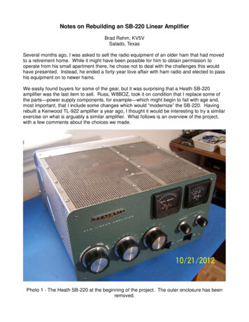
Notes on Rebuilding an SB-220 Linear AmplifierBrad Rehm, KV5VSalado, TexasSeveral months ago, I was asked to sell the radio equipment of an older ham that had movedto a retirement home. While it might have been possible for him to obtain permission tooperate from his small apartment there, he chose not to deal with the challenges this wouldhave presented. Instead, he ended a forty-year love affair with ham radio and elected to passhis equipment on to newer hams.We easily found buyers for some of the gear, but it was surprising that a Heath SB-220amplifier was the last item to sell. Russ, W8BOZ, took it on condition that I replace some ofthe parts—power supply components, for example—which might begin to fail with age and,most important, that I include some changes which would “modernize” the SB-220. Havingrebuilt a Kenwood TL-922 amplifier a year ago, I thought it would be interesting to try a similarexercise on what is arguably a similar amplifier. What follows is an overview of the project,with a few comments about the choices we made.Photo 1 - The Heath SB-220 at the beginning of the project. The outer enclosure has beenremoved.
A Google search for SB-220 updates returned dozens of articles and reflector commentsabout this amplifier. So our first step was to download and look through this material todecide which of the changes would be worth making. Three classes of changes emerged:those for convenience, appearance, or endurance, those which improve stability, and thosewhich protect the amplifier against catastrophic failure. Let's look at the ones I chose toinstall.Convenience, Appearance, and Endurance Changes. These could be called cosmeticbecause they don't directly affect the operation of the amplifier. Adding nylon Molexconnectors to cable bundles, for example, makes it easier to service the unit when thetransformer or the front panel must be removed. The internal appearance of this amplifier,particularly of the tank circuit area, was improved by removing most of the components andcleaning the area with brushes and alcohol swabs. The perforated top and side panels wereremoved and cleaned with steel wool and abrasives to make them shine again. All of theoriginal wiring was removed and replaced with harnesses made with Teflon-insulated wire.The long-term endurance of the SB-220 can be improved by replacing the fan and adding astep-start circuit. Since this amplifier was thirty years old, I assumed it would better to replacethe motor and fan than to simply apply oil to the bearings of the old motor. The original fanblade was nicked in several places, so replacing it might reduce fan noise. Photo 8 showsthat I installed longer bolts on the motor so that fender washers could be placed on the insideand outside of the perforated metal on which the fan is mounted. This also helped reduce fannoise and vibration.Photo 2 - The components of the step-start circuit were located next to the circuit breakers
and the power cord entry. The cord and voltage-select jumpers have not yet been installed.For the final endurance change, we added a step-start circuit which limited the turn-on orinrush current due to the initial low resistance of the tube filaments and the high energydemanded by the filter capacitors when charging begins. I've used two approaches to thistask in other amplifier projects. The simplest inserts a negative temperature coefficient (NTC)thermistor in series with one of the incoming AC mains. These devices present a relativelyhigh resistance when cold and reduce their resistance to a small fraction of an Ohm whenthey become warm. Several commercial soft-start products use this approach.Another way to accomplish step-start places a resistor in series with one or both of the ACsupply leads and uses a relay to shunt the resistors after a two or three second delay. Thedesign of this kind of circuit is a little tricky because the circuitry that energizes the relay mayhave to work reliably at an initially low AC mains voltage. The resistor values must also bechosen carefully, because we would like them to be suitable for both 120 Volt and 240 Voltoperation.I chose the relay approach, shown in Photo 2 above, using a simple R-C and transistor timer.The start-up current requirement of an amplifier of this size can exceed the current ratings ofthe largest NTC thermistors, especially when the amp is operated at 120 Volts. The relayapproach can be very reliable if the resistors and relay are selected carefully. After a twosecond delay, two 15 Ohm, 5 Watt resistors in parallel in each leg of the incoming AC areremoved, using a double-pole, 20 Amp relay. The component values allow the simple, 28-Voltdelay circuit to operate properly at 120 and 240 Volts.Photo 2 shows the Magnecraft relay used to bypass each of the series resistors, which arelocated to the right and above the circuit breakers. The terminal strip to the left of the 3-500Zsocket contains the 28 Volt rectifier and delay circuit. The transformer which powers thiscircuit was bolted to the side panel on the top of the chassis. It is shown in Photos 3 and 12.The final schematic includes the relay control circuit and 28 Volt power supply.Also in this category were the following convenience and appearance changes:1. Molex connectors were installed in the high voltage transformer leads and in the wiringto the front panel. These are shown in Photos 3 and 4. The primary connectors wereMolex 50-84-1060 and 50-84-2060. The secondary connectors were Molex 50-841040 and 50-84-2040.2. The incandescent lamps which illuminate the meters were replaced with white LEDs.The 5 Volt filament power was rectified and filtered, then current-limited with individualresistors for each LED.3. Harbach capacitor board was installed in the power supply. In addition to improvingthe appearance of the capacitor bank, the capacitor board includes new bleederresistors and adds reverse diodes to protect the amplifier during tube flashovers. Theold and new capacitor wiring is show in Photos 5 and 6. Notice the damage to theoriginal transformer secondary lead from arcing through the insulating sleeving inPhoto 5.4. The Harback SB-220 diode board uses newer 1N5408 diodes, which increase thepeak current rating from 1 to 3 Amperes. An additional diode was installed on the backof the board to reduce the chance of damage from tube flashovers. (See thediscussion of this change below.)
5. The ALC circuitry wasremoved becausereliable ALC loops arealready incorporatedin moderntransceivers.6. The three-poleantenna- and biasswitching relay wasdiscarded, andseveral componentswere added toreplace it. Thevacuum relays areshown in Photo 7.The upgradesaccomplished withthe W7RY QSKBoard are discussedbelow. All coax in theSB-220 was replacedwith Teflon dielectric,RG-303.Photo 3 Molex connectors as installed at the high voltage power transformer. The connectorsmake it easier to remove the transformer for shipping. The original transformer was replacedwith a Harbach/Peter W. Dahl unit, which increased the available high voltage from about3200 to nearly 3500 Volts. This photo also shows the Alpha Wire sleeving which was installedon the transformer secondary leads. The breakdown rating of the sleeving is 8000 Volts.Photo 4 The Harbachdiode board, whichreplaces the originalvoltage doubler board.The area of this boardwhich contained the zenerdiode replacement is notpopulated because thisfunction is performed bythe W7RY QSK Board.Also visible in this photo isthe Molex connectorwhich allows detachingand removing the frontpanel. The fuse, visibleon the left side of thephoto, protects the power
supply and meters from tube flashovers. Not visible here is the diode recommended by W8JIto provide additional flashover protection for the meters. It has been soldered to the back ofthe diode board between terminal C and ground.Photo 5 - The original capacitor and diode board wiring. Notice the arc damage to the originaltransformer secondary wire and sleeving.Photo 6 - The Harbach capacitor and diode boards replaced the original wiring and PWB.Alpha Wire sleeving was used on all the high voltage wiring. The new front panel wiring andwhite meter LEDs are also visible in this photo.
Photo 7 - Kilovac HC-2 vacuum relays are shown in this photo. The resistor which setscurrent through the relays at 60 mA will be installed on the terminal strip between the relays.The relays are mounted in rubber grommets (Mouser 534-750) to reduce mechanicalswitching noise. Also visible in this photo are the parallel 10 Ohm resistors in series with thecoax and RF drive to the filaments. These reduce the Q of the bandswitch-to-tube wiring.Improvements for Stability. Some SB-220s tended to develop parasitic oscillations,particularly when used on the higher HF bands. This problem appeared not only in the Heathamplifiers but in a number of competing production amps of the same vintage. The parasiticsuppressors placed in series with each of the tube plate leads are usually responsible. Youwill find a variety of opinions about how suppressors should be built. Many designers feel thatthe three-to-five turn inductors around or adjacent to Q-killer resistors do not make goodparasitic chokes. Even though the Q of these chokes can be made low, the fact that they'retypically resonant in the VHF range means that they can support parasitics.Hairpin loops shunted by low-inductance resistors have self-resonant frequencies well abovethe VHF range and appear to work well as parasitic suppressors. The loops are typically justwide enough to allow the resistors to be soldered across the bases, and they are madesomewhat longer than they are wide. I haven't seen the loop dimensions fully-defined yet, butRichard Measures, AG6K, gives a fairly complete description in his on-line paper on the TL922 and the SB-220. (See the “Anode Circuit Modification” section ofhttp://www.somis.org/QSK922.html.) Although Measures also recommends using nichromewire for the loop, I have found 12-gauge, tinned buss wire to be satisfactory. Photo 8 showsthe hairpin loops installed in this SB-220. Observing the output of the amp with a spectrumanalyzer, I have found no tendency to oscillate, even under a variety of load conditions.
Photo 8 - The hairpin parasitic chokes are supported by the plate choke. The Q-killerresistors are placed at the “bottom” of each choke. Notice the ceramic disc capacitor whichwas added at the base of the plate choke. The new fan and motor are visible to the left of thetubes. The mounting bolts were replaced with longer ones, which permitted using fenderwashers on the inside and outside surfaces of the intake grill. These reduced motor vibration.The small transformer above the fan motor was later moved to the opposite side of the fanbecause the space was needed for the larger Peter W. Dahl transformer.Protecting Against Catastrophic Failure. This category could be subsumed under the stabilityimprovement heading, since some failures are related to parasitic oscillations. I prefer toconsider it separately because there is a class of failure which occurs because of suddendischarges inside the tubes. Design choices can't eliminate the chance of a discharge, butthey can reduce the damage that follows when a discharge occurs. Tom Rauch, W8JI, haswritten a technically competent discussion of this phenomenon. (Seehttp://www.w8ji.com/fault protection.htm.) Internal discharges typically occur between theanode (plate) of the tube and the cathode (or filament). When this happens the control gridscan be driven positive, causing hundreds of amperes of current to flow through the tubes andtheir bias circuit. The tubes are lost. The meters are usually destroyed. And many smallercomponents fail.The first step in preventing this kind of damage is to abandon the practice of isolating thegrids of the tubes from ground with chokes, resistors, or fuses. Photo 7 shows resistorsinstalled between one of the grid terminals on each tube and each grid pin taken to RFground with pairs of capacitors. These were replaced with buss wire connections to ground.The ground connection ensures that the grids can never be driven very positive in a flashover
event.Flashovers and damage can occur for other reasons; however, so additional changes wereintroduced. First, fast-blow, 1 Amp fuses were installed in series with the plate B lead and inseries with the center tap of the filament transformer secondary. These limit the current whichcan flow during a flashover event. Second, a diode was installed from terminal C on thediode board to ground. Shown on the schematic, this diode clamps the negative rail, to whichthe plate current meter is connected, at about 1 Volt.Finally, a W7RY “QSK Board” was installed to improve amplifier operation and, mostimportant, reduce the chance of a particular kind of failure. Jim offers (or plans to offer)boards for L4B, SB-200, Ameritron, and TL922 amps, as well as for the SB-220. The boardsare sold on EBay Board-LinearAmplifier-QSK-System-/281039165121), but a brief explanation of how the design evolvedcan be found at -now-available.html.The original Heathkit design rectified voltage from a separate winding on the filamenttransformer to develop about 115 Volts DC. This was applied to the antenna/bias changeoverrelay, and it appeared at the “Relay” connector at the rear of the amp. Modern transceiversare not designed to handle the voltage and current involved, so an interface is normally usedto protect the transceiver. The QSK Board rectifies the AC from the transformer and uses aZener diode to develop 12 Volts for on-board circuitry. The latter includes a transistor bufferwhich reduces “Relay” current seen by the transceiver to about 10 mA.The QSK Board includes two other important circuits. One is an adjustable, precisionregulated supply which drives a power-Darlington transistor to control the 3-500Z operatingbias. The transmit/standby bias levels are selected by a signal derived from the “Relay”circuit.The other circuit controls the antenna changeover relays. Jim recommends using a reedrelay at the amp input and a vacuum relay at the output. His schematic includes resistorswhich equalize the currents in the two series-connected relays. Having had unhappyexperiences with reed relays in other applications, Russ and I chose to use two Kilovac HC-2vacuum relays. HC-1s might have been a better choice, but HC-2s were on-hand, and theyhave worked well in the project as well as several others. Since plenty of voltage is availableto operate the series-connected relays, they switch very rapidly. A series resistor limitscurrent to about 60 mA. Adding a capacitor across the resistor could have been used tofurther reduce switching time, but this was not deemed necessary.The QSK Board has a role in preventing catastrophic failures in the SB-220, because a failuremode of the Zener diode which controls cathode bias in the original circuit is a short circuit.When the Zener fails in this manner, the tubes are turned fully on, and damage can resultwhen excessive current flows. The QSK Board uses a TIP147 power transistor which isprotected by an MOV (a Metal-Oxide Varistor). If the transistor should fail, the voltage acrossthe varistor would rise to its 130 Volt avalanche rating, thus biasing the tubes into cut-off. Thenormal failure mode for an MOV is to go open, but this only occurs after the part has beendriven into conduction many times. The scheme isn't completely failure-proof, but I believe it'sless failure-prone than the original circuit. The installed board is shown in Photo 9.
Photo 9 - The finished underside of the amp. The QSK Board is on the lower-right in thisphoto. The Darlington bias-control transistor and filament center-tap fuse are mounted justabove it, using available chassis holes.Final Thoughts. With the exception of a transistor failure on the W7RY QSK board (probablya random failure event); the amp has performed well for several months. Some commentsabout its behavior are in order:Substituting the Harbach/Peter W. Dahl transformer for the original high-voltage transformerresulted in several changes in the behavior of the amp. The resting plate voltage increasedfrom an indicated 3200 Volts to nearly 3500 Volts. As a result, less exciter power is requiredto drive the amp to 1500 Watts output. Prior to the change, 90 to 100 Watts of drive producedabout 1400 Watts peak output in SSB mode. After the change, 80 to 90 Watts produced 1400to 1500 Watts peak output.These measurements were made using an Array Solutions Power Master wattmeter and aPalstar DL2K load. More importantly, when the original 3-500Z tubes were replaced with newRF Parts 3-500ZGs, 1500 Watts was attainable with 70 to 80 Watts drive.
When the original tubes were used, other stations reported that transmitted audio soundedbetter—less distorted—when the drive power was reduced to 75 Watts. At this level, thepower output was about 1200 Watts. The new RF Parts 3-500ZGs could be operated at 1400to 1500 Watts with no degradation in signal quality. Clearly, to keep distortion products undercontrol, we would have to settle for less power output with the original tubes. (The RF Partstubes were borrowed for testing from another amplifier project.)Since I am primarily a CW op, I hoped to be able to run the SB-220 at full power from time totime. This not advisable, because the voltage rating of the plate tuning capacitor is not highenough to allow it. Arcing between the plates can occur at 1500 Watts, so CW on the SB-220is recommended only in “CW/TUNE” mode, where output is about 1000 Watts with 80 Wattsdrive (using the original tubes). Curiously, I've seen no capacitor arc-overs when running theamp at 1500 Watts in SSB mode.On two occasions, idle current and power output fell to half normal. A quick look at the tubesrevealed that one filament was not lit. Russ remembered that other SB-220 owners hadreported that this can be caused by oxidation on the tube socket pin receptacles. I cleanedthe receptacles with Q-tips which had been saturated in an electronic contact cleaner solution.The Q-tips turned dark. The tube filaments have lit reliably ever since.Photos 10 through 13 show the beginning stages of the project and the finished amp with theHarbach/Peter Dahl transformer installed, with the necessary changes to the enclosure.Photo 10 - Most components have been removed so that the chassis can be cleaned and oldhardware can be replaced. The resistor which feeds high voltage to the bypass capacitor andplate choke was also replaced
Photo 11 - Another view of the chassis, ready for rewiring. One RCA connector on the rear ofthe chassis was removed. The other was replaced with a BNC at the “Relay” input.Photo 12 - This view shows the Harbach/Peter Dahl HV transformer, which is slightly largerthan the original transformer. The 24 Volt transformer which supplies power for the step-startcircuit has been moved to the lower-right corner to make room for the Harbach.
Photo 13 - It was necessary to cut a rectangular hole in the right-side panel to make room forthe Harbach transformer. The transformer will not interfere with the outer enclosure for theamp.We would appreciate hearing about your SB-220 project. You may have comments aboutdifferent approaches and better ways of doing what we did. If you'd like to hear the SB-220 inoperation, join us and our friends on Saturday and Sunday mornings on 7.138 MHz, 5:15 to8:00 am, US central time.73,Brad Rehm, KV5V(with Russ Gates, W8BOZ)1/14/13Nb. Looking at the schematics after having them scanned at an office supply store, I noticedsomething which everyone will want to correct. The fuse in the high-voltage line to the platechoke is on the supply side of the Interlock. If the cover plate is removed soon after turningthe amp off, the Interlock will try to crowbar the supply, but the fuse will open when the currentexceeds 1 amp. This will make the tube compartment safe, but the capacitors in the HVsupply will probably not be fully discharged at this time.The solution: Either remove the Interlock switch and be careful! (Bad idea.) Or move thefuse. Install it in series with the HV lead to the RF choke. Be safe! (Good idea.)***
Jan 14, 2013 · Photo 2 shows the Magnecraft relay used to bypass each of the series resistors, which are located to the right and above the circuit breakers. The terminal strip to the left of the 3-500Z socket contains the 28 Volt rectifier and delay circuit. The transformer which powers this circuit