Transcription
Installation InstructionsMP-Series Low-inertia Servo Motor with215 mm or Larger Frame SizeCatalog Numbers MPL-B640, MPL-B660, MPL-B680, MPL-B860, MPL-B880, MPL-B960, MPL-B980TopicPageImportant User Information2Catalog Number Explanation3About the MP-Series Low-inertia Motors4Before You Begin4Install the Motor9ATEX Motor Installations13Product Dimensions14Motor Load Force Ratings16Connector Data18Remove and Install a Shaft Key19Motor Cables and Accessory Kits20Specifications21Additional Resources22
2 MP-Series Low-inertia Servo Motor with 215 mm or Larger Frame SizeImportant User InformationRead this document and the documents listed in the additional resources section about installation, configuration, and operation ofthis equipment before you install, configure, operate, or maintain this product. Users are required to familiarize themselves withinstallation and wiring instructions in addition to requirements of all applicable codes, laws, and standards.Activities including installation, adjustments, putting into service, use, assembly, disassembly, and maintenance are required to becarried out by suitably trained personnel in accordance with applicable code of practice.If this equipment is used in a manner not specified by the manufacturer, the protection provided by the equipment may be impaired.In no event will Rockwell Automation, Inc. be responsible or liable for indirect or consequential damages resulting from the use orapplication of this equipment.The examples and diagrams in this manual are included solely for illustrative purposes. Because of the many variables andrequirements associated with any particular installation, Rockwell Automation, Inc. cannot assume responsibility or liability for actualuse based on the examples and diagrams.No patent liability is assumed by Rockwell Automation, Inc. with respect to use of information, circuits, equipment, or softwaredescribed in this manual.Reproduction of the contents of this manual, in whole or in part, without written permission of Rockwell Automation, Inc., isprohibited.Throughout this manual, when necessary, we use notes to make you aware of safety considerations.WARNING: Identifies information about practices or circumstances that can cause an explosion in a hazardousenvironment, which may lead to personal injury or death, property damage, or economic loss.ATTENTION: Identifies information about practices or circumstances that can lead to personal injury or death,property damage, or economic loss. Attentions help you identify a hazard, avoid a hazard, and recognize theconsequence.IMPORTANT Identifies information that is critical for successful application and understanding of the product.Labels may also be on or inside the equipment to provide specific precautions.SHOCK HAZARD: Labels may be on or inside the equipment, for example, a drive or motor, to alert people thatdangerous voltage may be present.BURN HAZARD: Labels may be on or inside the equipment, for example, a drive or motor, to alert people thatsurfaces may reach dangerous temperatures.ARC FLASH HAZARD: Labels may be on or inside the equipment, for example, a motor control center, to alertpeople to potential Arc Flash. Arc Flash will cause severe injury or death. Wear proper Personal ProtectiveEquipment (PPE). Follow ALL Regulatory requirements for safe work practices and for Personal ProtectiveEquipment (PPE).Rockwell Automation Publication MP-IN002E-EN-P - January 2015
MP-Series Low-inertia Servo Motor with 215 mm or Larger Frame Size 3Catalog Number ExplanationMP L - B x 80 x - x x x x A xFactory Designated Options StandardAH ATEX protection rating of Group II, Zone 2Mounting FlangeA IEC metricBrake2 No brake4 24V DC brakeConnectors2 Bayonet, right angle, 180 rotatable7 Circular DIN, right angle, 180 rotatableEnclosure/Shaft Key/Shaft SealJ Shaft keyK No shaft keyFeedbackM Multi-turn high-resolution encoderS Single-turn high-resolution encoderRated SpeedA 500 rpmB 1000 rpmC 1500 rpmD 2000 rpmE 2500 rpmF 3000 rpmG 3250 rpmH 3500 rpmJ 3750 rpmK 4000 rpmMagnet Stack Length (80 8.0 in.)Frame Size (IEC 72-1 flange number)6 215 mm8 265 mm9 300 mmVoltage ClassB 400VSeries TypeL Low inertiaSeriesMP Premium permanent magnetrotary servo motorRockwell Automation Publication MP-IN002E-EN-P - January 2015
4 MP-Series Low-inertia Servo Motor with 215 mm or Larger Frame SizeAbout the MP-Series Low-inertia MotorsMP-Series low-inertia (Bulletin MPL) motors feature single-turn or multi-turn high resolutionencoders, and are available with 24V DC brakes. These compact brushless servo motors meet thedemanding requirements of high-performance motion systems.Before You BeginRemove all packing material, wedges, and braces from within and around the item. Afterunpacking, verify the nameplate catalog number against the purchase order.ATTENTION: To avoid personal injury and damage to the motor, do not lift or handle the motor by themotor shaft. The cap on the shaft can come loose and cause you to drop the motor.1. Remove the motor carefully from its shipping container.2. Visually inspect the motor for any damage.3. Examine the motor frame, front output shaft, and mounting pilot for any defects.4. Notify the carrier of any shipping damage immediately.Keep the original packing material in case you need to return the product for repair or transportit to another location. Use both the inner and outer packing cartons to provide adequateprotection for a unit returned for service.ATTENTION: Do not attempt to open or modify this motor beyond changing the connectororientation as described on Change Connector Orientation on page 9.Only an authorized Allen-Bradley repair center can service this item. Refer to Rockwell AutomationSupport for assistance to locate the nearest repair center.Store or operate your motor in a clean and dry location within the environmental conditionslisted in Specifications on page 21.Removing the Shaft CapUse your hand to remove the protective cap that is installed on the motor shaft or pry off the capwith a screwdriver. Do not use a hammer or other tools as they can damage the motor shaft.Rockwell Automation Publication MP-IN002E-EN-P - January 2015
MP-Series Low-inertia Servo Motor with 215 mm or Larger Frame Size 5To Prolong Motor LifeProper design and maintenance can increase the life of a servo motor. Follow these guidelines tomaximize the life of a servo motor within your environment: Always provide a drip loop in each cable to carry liquids away from the connection to themotor.The cable enters beneath themotor and forms a drip loop.The cable enters above themotor and does not form adrip loop. If possible, provide shields that protect the motor housing, shaft seals, and theirjunctions from contamination by foreign matter or fluids. Shaft seals are subject to wear and require periodic inspection and replacement.Replacement is recommended every 3 months, not to exceed 12 months, depending onuse. Refer to Shaft Seal Kits on page 20 for more information on shaft seals. Inspect the motor and seals for damage or wear on a regular basis. If damage or excessivewear is observed, replace the item. The brake option on this servo motor is a spring-set holding brake that releases whenvoltage is applied to the brake coil. A separate power source is required to disengage thebrake. This power source can be applied by a servo motor controller or manual operatorcontrol.If system main power fails, holding brakes can withstand occasional use as stoppingbrakes. However, this creates rotational mechanical backlash that can cause damage tothe system, increase brake wear, and reduce brake life.IMPORTANTHolding brakes are not designed to stop rotation of the motor shaft, and they are not intended tobe used as a safety device. They are designed to hold a motor shaft at 0 rpm for up to the ratedbrake holding torque.Follow these steps to prevent motor shaft rotation.1.2.3.4.Command the servo drive to 0 rpm.Verify the motor is at 0 rpm.Engage the brake.Disable the drive.Disabling the drive removes the potential for brake wear caused by a badly-tuned servosystem oscillating the shaft.Rockwell Automation Publication MP-IN002E-EN-P - January 2015
6 MP-Series Low-inertia Servo Motor with 215 mm or Larger Frame SizeUsing Shaft SealsAn additional seal is required on the motor shaft near the motor front bearing if the shaft isexposed to fluids or significant amounts of fine dust. This includes lubricating oil from agearbox. An IP66 rating for the motor requires the use of a shaft seal and environmentally sealedconnectors/cables. The additional seal is not recommended in applications where the motorshaft area is free of liquids or fine dust, and a lower rating is sufficient: Refer to Specifications on page 21 for a brief description of the IP rating for theseMP-Series motors. Refer to Shaft Seal Kits on page 20 to find the catalog numbers of seal kits available foryour motor. Refer to Kinetix Motion Accessories Specifications, publication GMC-TD004, to findenvironmentally sealed connectors and cables compatible with the MP-Series motors.Using Couplings and PulleysMechanical connections to the motor shaft, such as couplings and pulleys, require a torsionallyrigid coupling or a reinforced timing belt. The high dynamic performance of servo motors cancause couplings, pulleys, or belts to loosen or slip over time. A loose or slipping connection cancause system instability and damage the motor shaft. All connections between the system and theservo motor shaft must be rigid to achieve acceptable response from the system. Periodicallyinspect connections to verify their rigidity.When mounting couplings or pulleys to the motor shaft, be sure that the connections areproperly aligned and that axial and radial loads are within the specifications of the motor. Referto Shaft Seal Kits on page 20 for guidelines to achieve 20,000 hours of motor bearing life.ATTENTION: Damage can occur to the motor bearings and the feedback device if sharp impact tothe shaft is applied during installation of couplings and pulleys. Damage to the feedback device canresult by applying leverage from the motor mounting face to remove devices mounted on themotor shaft.Do not strike the shaft, couplings, or pulleys with tools during installation or removal. Use a wheelpuller applying pressure from the user end of the shaft to remove any friction-fit or stuck devicefrom the motor shaft.Rockwell Automation Publication MP-IN002E-EN-P - January 2015
MP-Series Low-inertia Servo Motor with 215 mm or Larger Frame Size 7Preventing Electrical NoiseElectromagnetic interference (EMI), commonly called noise, can adversely impact motorperformance by inducing stray signals.Follow these guidelines to prevent the effects of EMI: Isolate the power transformers, or install line filters on all AC input power lines. Separate signal cables from motor cabling and power wiring. Do not route signal cableswith motor and power wires, or over the vent openings of servo drives. Ground all equipment by using a single-point parallel ground system that employsground bus bars or large straps. If necessary, use additional electrical noise reductiontechniques to reduce EMI in noisy environments.Refer to System Design for Control of Electrical Noise Reference Manual, publicationGMC-RM001, for additional information on reducing the effects of EMI by improving thesystem level electromagnetic compatibility (EMC).Build and Install the CablesCorrect cable routing and careful cable construction improves system electromagneticcompatibility (EMC).Follow these guidelines to build and install the cables: Keep the wire lengths as short as possible. Route noise sensitive wiring (encoder, serial, and I/O) away from input power and motorpower wiring. Separate cables by 0.3 m (1 ft) minimum for every 9 m (30 ft) of parallel run. Ground both ends of the encoder cable shield and twist the signal wire pairs to preventEMI from other equipment.ATTENTION: High voltage can be present on the shield of a power cable, if the shield is notgrounded.Verify that there is a connection to ground for any power cable shield.ATTENTION: MP-Series motors produce leakage current in the protective earthing conductor thatexceeds 3.5 mA AC and/or 10 mA DC.Be sure to properly ground the motor cables per the drive installation instructions.Rockwell Automation Publication MP-IN002E-EN-P - January 2015
8 MP-Series Low-inertia Servo Motor with 215 mm or Larger Frame SizeGround Shielded Signal Wires within a Power CableAlways connect the shield on any signal wire pair routed inside a power cable to the overallmachine ground.If you are installing a 2090-XXNPMF-xxSxx or 2090-CPBM4DF-xxAFxx power with brakecable, loop the signal wire pairs to the overall cable shield as shown in Grounding of Signal WireShields in a Power Cable on page 8. Then clamp all of the shields together in the power cable(chassis) ground connection on the drive.Grounding of Signal Wire Shields in a Power CableFactory SuppliedShielded Signal Wires (two pairs) within Power CableOverall Power Cable ShieldField ModifiedSignal Wire Shield (one of two) Contacts Overall PowerCable ShieldAll power and signal wire shields must connect to machine ground.2090-XXNPMF-xxSxx (shown) contains two signal wire pairs.2090-CPBM4DF-xxAFxx contains one signal wire pair.The diagram shows one of the two signal wires in the correctposition. Connect both signal wire shields and the overall powercable shield to machine ground.The signal wire pairs within a power cable often carry a 24V DC brake signal, but can also carrylogic signals. Grounding the shield that surrounds the signal wires dissipates an induced voltageand reduces the effects of EMI.Rockwell Automation Publication MP-IN002E-EN-P - January 2015
MP-Series Low-inertia Servo Motor with 215 mm or Larger Frame Size 9Install the MotorMP-Series motors include a mounting pilot for aligning the motor on the machine. Preferredfasteners are hardened steel. The installation must comply with all local regulations and useequipment and installation practices that promote safety and electromagnetic compatibility.ATTENTION: Unmounted motors, disconnected mechanical couplings, loose shaft keys, anddisconnected cables are dangerous if power is applied.Lock-out and tag-out disassembled equipment (restrict electrical power).Before applying power to the motor, remove the shaft key and other mechanical couplings that canbe thrown from the shaft.ATTENTION: Make sure that cables are installed and restrained to prevent uneven tension orflexing at the cable connections.Excessive and uneven lateral force on the cable can inhibit environmental sealing as the cableflexes.Change Connector OrientationYou can rotate the connector housings up to 180 . The M23 feedback connector and the M23 and M40 power/brake connectors arerotatable. The M58 power/brake connector, on MPL-B8xx and MPL-B9xx motors with highercurrent requirements, must be removed and repositioned in 90 increments.This lets you rotate the connector into a position that best protects the connection from possibleenvironmental contaminates while providing cable access.ATTENTION: Connectors are designed to be rotated into a fixed position during motor installation,and remain in that position without further adjustment. Do not rotate the connector multipletimes, and do not use tools or excessive force to rotate the connector. Excessive rotation or force candamage the connector seal and reduce the international protection (IP) rating of the motor asoutlined in Specifications on page 21.Rotate the M23 Feedback or M40 Power/Brake Circular DIN ConnectorFollow these steps to rotate an M23 feedback or a M40 power/brake connector.1. Mount and fully seat a mating cable on either the feedback or power/brake connector.2. Grasp the mated connector and cable plug with your hands and slowly rotate them to theoutside of the motor.ATTENTION: Apply force to only the motor connector and cable plug. Do not apply force to thecable extending from the cable plug. Do not use tools (for example, pliers and vise-grips) to rotatethe connector.Rockwell Automation Publication MP-IN002E-EN-P - January 2015
10 MP-Series Low-inertia Servo Motor with 215 mm or Larger Frame SizeRotate the M58 Power/Brake Circular DIN ConnectorFollow these steps to rotate a M58 power/brake DIN connector.1. Remove the four locking screws that attach the connector housing to the motor body.2. Rotate the connector housing 90 or 180 .If binding of the wire bundles prevents rotation of the connector, follow these steps toaccess the internal motor wiring.a. Remove the eight screws from the rear cover of the motor.b. Carefully reposition the wires around the perimeter of the motor feedback deviceunder the rear cover.Make sure that the white sleeving stays in place to help protect the wires where theygo through the end cap.c. Verify that the wires are not close to any rotating parts.d. Verify that the O-ring and all wires are positioned correctly.e. Replace the rear cover and torque the screws to 0.68 0.90 N m (6.0 8.0 lb in) tosecure the rear cover.3. Torque the locking screws to 6.8 N m (60 lb in) to secure the connector housing to themotor body.Mount the MotorFollow these steps to mount the motor.ATTENTION: Damage can occur to the motor bearings and the feedback device if sharp impact tothe shaft is applied during installation of couplings and pulleys.Do not strike the shaft, couplings, or pulleys with tools during installation or removal.1. Provide sufficient clearance, heatsink mass, and airflow for the motor so it stays withinthe operating temperature range of 0 40 C (32 104 F).Do not enclose the motor unless cooling air is forced across the motor, and keep otherheat producing devices away from the motor. Heatsink requirements are listed in afootnote to the Specifications on page 21 table.ATTENTION: Outer surfaces of the motor can reach high temperatures of 125 C (275 F)during operation.Take precautions to prevent accidental contact with hot surfaces. Consider motor surfacetemperature when selecting connections and cables to install on a motor.2. Verify the axial and radial shaft loads of your application do not exceed those listed in theMotor Load Force Ratings on page 16.3. Position the motor on the machine with its connectors pointing downward.Rockwell Automation Publication MP-IN002E-EN-P - January 2015
MP-Series Low-inertia Servo Motor with 215 mm or Larger Frame Size 114. Insert and hand-tighten the fasteners in each of the four mounting holes in the motorfaceplate.5. The mounting hole diameter is specified in the Product Dimensions on page 14 table.6. Align the motor on the machine by using the mounting pilot hole to verify the correctalignment.7. Tighten the fasteners within the recommended torque range.Cat. No.Torque RangeMPL-B6xx, and MPL-B8xx8 20 N m (70 180 lb in)MPL-B9xx17 45 N m (150 400 lb in)8. Rotate the shaft for electrical phasing and encoder alignment.The index pulse occurs on a single-turn encoder when the shaft key is aligned with theconnectors. Refer to Product Dimensions on page 14 for a visual reference of thisalignment.Rockwell Automation Publication MP-IN002E-EN-P - January 2015
12 MP-Series Low-inertia Servo Motor with 215 mm or Larger Frame SizeAttach the Motor CablesFollow these steps to attach the feedback and power/brake cables after the motor is mounted.ATTENTION: Servo drive power must be turned off before connecting or disconnecting the cables tothe motor, and if a cable is left disconnected at the motor end.Arcing or unexpected motion can occur if the feedback, power, or brake cables are connected ordisconnected while power is applied to the servo drive.ATTENTION: Be sure that cables are installed and restrained to prevent uneven tension or flexing atthe cable connectors. Provide support at 3 m (10 ft) intervals throughout the cable run.Excessive and uneven lateral force at the cable connectors can result in the connector’s environmentalseal opening and closing as the cable flexes, or wires separating at the cable gland.1. If you are using the Threaded DIN (M4) Cable Plugs, install the O-rings.An O-ring on the connector is necessary to achieve the maximum environmental rating.Groove Reservedfor Cable PlugInstall the O-ring on the SpeedTec-ready DIN motor connector whenyou are using the threaded DIN (M4) cable plugs.Verify that the O-ring is not damaged, not twisted, and rests in thegroove near the rear of the connector.SpeedTec-ready DINMotor ConnectorThreaded DIN (M4) Cable Plug 2090-XXNxMF-Sxx standard feedbackand power cables 2090-CxxM4DF-xxAFxx continuous-flexfeedback, power, and power/brake cables2. If you are using the SpeedTec DIN (M7) Cable Plugs, do not install the O-rings.Do not install the O-ring on the SpeedTec-ready DIN motor connectorwhen you are using the SpeedTec DIN (M7) cable plugs.SpeedTec-ready DINMotor ConnectorsSpeedTec DIN (M7) Cable Plug 2090-CFBM7Dx-xxAxxx standard andcontinuous-flex feedback cables 2090-CPxM7DF-xxAxxx standard andcontinuous-flex power/brake cables3. Form a drip loop in the cable (see page 5).Rockwell Automation Publication MP-IN002E-EN-P - January 2015
MP-Series Low-inertia Servo Motor with 215 mm or Larger Frame Size 134. Carefully align the flat surface on the feedback or the power/brake cable plug (shown inthe diagram) with the flat surface on the motor connector.IMPORTANT The motor orientation shown is used to clearly show the alignment marker on each cable socket.The recommended motor orientation when installed positions the connectors at the bottom of themotor.Power Plug OptionsFeedback Plug OptionsTop of connector isrelative to motororientation.Tab onSideFlat Surface withLogo on TopFlat Surface withLogo on TopTab onTopConnector plugs have either a tab or a flat surface with a logo to indicate the alignment point.5. Hand tighten the collar on the plug to fully seat it on the connector: Threaded DIN (M4) cable plugs require five to six revolutions. SpeedTec DIN (M7) cable plugs require approximately one-quarter of a revolution.TIPA fully-seated threaded plug leaves a small opening, approximately 1 4 mm(0.04 0.16 in.), between the connector and the plug.Do not apply excessive force when mating the cable plug with the motor connector. If the plugand connector do not go together with light hand force, realign the flat surfaces and try again.ATTENTION: Align the keyed connectors and hand-tighten the recommended number of turns.If you cannot tighten the connectors by hand, verify that the keyed connectors are properly aligned.Do not use tools (for example, pliers and vise-grips) to tighten the connectors.ATEX Motor InstallationsIf your motor has an ATEX rating for hazardous environments, complete the following step. Thecatalog number on ATEX motor nameplates ends with H, for example MPL-xxxx-xxxxxH.Verify the continuity and functionality of the thermal switch signals, TS and TS-, transmittedthrough the feedback cable that connects the motor to its controlling drive.ATTENTION: It is mandatory that the motion system monitor the thermal switch signals from amotor requiring an ATEX rating.The intrinsic safety protection concepts in the ATEX Direction 94/9/EC must be enabled byconnecting the thermal switch signals from the motor to the motion control system.Rockwell Automation Publication MP-IN002E-EN-P - January 2015
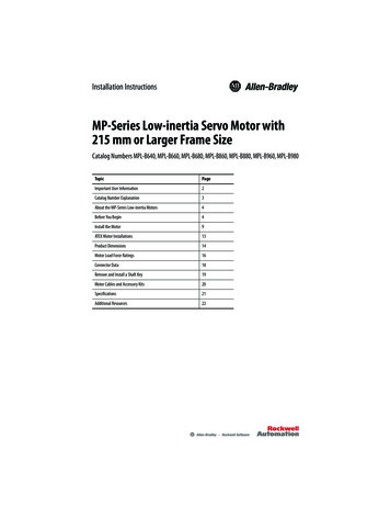
Rockwell Automation Publication MP-IN002E-EN-P - January 2015HDHDADADLLEM58 Power/Brake Connector onMPL-B8xx-xx7xAA and MPL-B9xx-xx7xAAwith Higher Current RequirementsLDM40 Power/Brake Connector onMPL-B6xx-xx7xAA, MPL-B8xx-xx7xAA, andMPL-B9xx-xx7xAALE3.86 (0.152) Tooling Cut Only for MPL-B6xxLBThis section provides dimensions for the motors.Product Dimensions3.86 mm (0.152 in.)Only MPL-B6xxMPL-B9xxØ 51.89 .07 mm(2.043 0.003 in.)MPL-B8xxØ 44.91 .05 mm(1.768 0.002 in.)MPL-B6xxØ 39.90 .05 mm(1.57 0.002 in.)L-LBLATDFMPL-B6xxTooling Cut3.73 mm (0.147 in.) Mounting SurfaceOnly MPL-B8xx and MPL-B9xxØ 108 (4.25)Only MPL-B6xxM23 FeedbackConnectorMPL-B6xx Flush [ 0.84 (0.033 in.)]with 3.86 mm (0.152 in.) Pilot Surface.MPL-B8xx and MPL-B9xx Flush [ 0.84 (0.033 in.)]with 3.73 mm (0.147 in.) Mounting Surface.M23 FeedbackConnectorShaft End HoleThread and DepthTooling Cut Only forMPL-B6xx (see close-up)Shaft KeyMPL-B6xx 10 x 8 x 59 mm (0.394 x 0.315 x 2.32 in.)MPL-B8xx 12 x 8 x 79 mm (0.472 x 0.354 x 3.11 in.)MPL-B9xx 14 x 9 x 79 mm (0.551 x 0.354 x 3.11 in.)GEABABPS (diameter of holes)M (diameter of bolt circle)NM58 Power/BrakeConnectorM40 Power/BrakeConnector(Pilot Diameter)14 MP-Series Low-inertia Servo Motor with 215 mm or Larger Frame Size
MP-Series Low-inertia Servo Motor with 215 mm or Larger Frame Size 15The dimensions in the table are for non-brake motors with a single-turn or multi-turn encoder.Footnotes provide tolerances for the common dimensions, and the additional dimensions for thebrake motors.DimensionsMotorCat. No.ABADD (3)F (4)GE (5)HDL (7), (8)L-LB (8)LAmm (in.)mm (in.)mm (in.)mm (in.)mm (in.)mm (in.)mm (in.)mm (in.)mm )5.20(0.205)MPL-B680MPL-B860246.5(9.70)127.0 (1)(5.0)189.5 (2)(7.46)42.002(1.6536)405.4(15.96)307.1 2 5.70(0.224)338.8 0.90)(1)These measurements are for a MPL-Bxxx motor with an M58 power/brake connector. On a MPL-B8xx motor with an M40 power/brake connectorthe measurement is 93.6 mm (3.68 in.). On a MPL-B9xx motor with an M40 power/brake connector the measurement is 93.8 mm (3.69 in.).(2)These measurements are for a MPL-Bxxx motor with an M58 power/brake connector. On a MPL-B8xx motor with an M40 power/brake connectorthe measurement is 179.0 mm (7.05 in.). On a MPL-B9xx motor with an M40 power/brake connector the measurement is 205.35 mm (8.08 in.).(3)Tolerance for this dimension is 0.016 mm ( 0.0006 in.).(4)Tolerance for this dimension is: MPL-B6xx -0.036 mm (-0.0014 in.);MPL-B8xx -0.043 mm (-0.0016 in.); and MPL-B9xx -0.43 mm (-0.0017 in.).(5)Tolerance for the dimension is MPL-B6xx -0.2 mm (-0.008 in.) MPL-B8xx -0.2 mm (-0.008 in.); MPL-B9xx -0.2 mm (-0.007 in.).(6)These measurements are for a MPL-Bxxx motor with an M58 power/brake connector. On a MPL-B8xx motor with an M40 power/brake connectorthe measurement is 296.5 mm (11.67 in.). On a MPL-B9xx motor with an M40 power/brake connector the measurement is 328.2 mm (12.92 in.).(7)If ordering an MPL-xxxx motor with a brake add: 108.0 mm (4.25 in.) to the MPL-B6xx dimension, 107.9 mm (4.26 in.) to the MPL-B8xx dimension;and 127.0 mm (5.0 in.) to the MPL-B9xx dimension.(8)Tolerance for this dimension is 0.7 mm ( .028 in.).TIPThese motors are designed to metric dimensions. Inch dimensions are mathematical conversions.Rockwell Automation Publication MP-IN002E-EN-P - January 2015
16 MP-Series Low-inertia Servo Motor with 215 mm or Larger Frame SizeDimensions (continued)LB (1)LD (1)LE (1)MN (2)PS (3)Tmm (in.)mm (in.)mm (in.)mm (in.)mm (in.)mm (in.)mm (in.)mm .9(7.0)344.1(13.55)299.7(11.80)228.7(9.0)MotorCat. No.Shaft EndThreaded Holemm .73(0.147)M12 x 1.75- 6Hthread depth28 (1.10)3.86(0.152)M16 x 2- 6Hthread depth36 (1.42)4.88(0.192)M16 x 2- 6Hthread depth36 .738)(1)For motors with a brake, for example MPL-Bxxx-xxx4AA, add to MPL-B6xx dimensions LB, LD. and LE: 108.0 mm (4.25 in.); to MPL-B8xxdimensions LB, LD. and LE:107.9 mm (4.26 in.); and to MPL-B9xx dimensions LB, LD 127.0 mm (5.0 in.).(2)Tolerance for the dimension is MPL-B6xx 0.014, -0.011 mm, ( 0.0005, -0.0005 in.); MPL-B8xx 0.016, -0.013 mm, ( 0.0006, -0.0005 in.);MPL-B9xx 0.016, -0.013 mm, ( 0.0005, -0.0006 in.).(3)Tolerance for the dimension is MPL-B6xx 0.43 mm ( 0.008 in.); MPL-B8xx and MPL-B9xx 0.52 mm ( 0.010 in.).Motor Load Force RatingsMotors are capable of operating with a sustained shaft load. The load force locations are shownin the figure and maximum values are in the tables.Loads are measured in kilograms; pounds are mathematical conversions.Load Forces on ShaftRadial load force applied at center of shaft extension.Axial Load ForceThe following tables represent 20,000 hour L10 bearing fatigue life at various loads and speeds.This 20,000 hour life does not account for possible application-specific life reduction that canoccur due to bearing grease contamination from external sources.Rockwell Automation Publication MP-IN002E-EN-P - January 2015
MP-Series Low-inertia Servo Motor with 215 mm or Larger Frame Size 17Radial Load Force RatingsMotor Cat. No.500 rpm1000 rpm1500 rpm2000 rpm3000 rpmkg (lb)kg (lb)kg (lb)kg (lb)kg (lb)MPL-B640253 (557)200 (442)—159 (351)139 (307)MPL-B660275 (607)219 (482)—173 (382)151 (334)MPL-B680291 (641)230 (508)—183 (404)160 (353)MPL-B860347 (764)275 (607—219 (481)—MPL-B880367 (810)292 (643—231 (510)—MPL-B960466 (1028)370 (816)323 (713)——MPL-B980494 (1089)392 (864)352 (775)——Axial Load Force Ratings (maximum radial load)Motor Cat. No.500 rpm1000 rpm1500 rpm2000 rpm3000 rpmkg (lb)kg (lb)kg (lb)kg (lb)kg (lb)MPL-B64089 (197)66 (146)—48 (107)41 (90)MPL-B66098 (217)72 (159)—54 (118)45 (99)MPL-B680104 (230)77 (169)—57 (125)47 (104)MPL-B860145 (320)107 (237)—79 (175)—MPL-B880153 (338)113 (250)—84 (185)—MPL-B960142 (314)105 (232)88 (194)——MPL-B980153 (338)113 (249)94 (207)——Axial Load
MP-Series Low-inertia Servo Motor with 215 mm or Larger Frame Size Catalog Numbers MPL-B640, MPL-B660, MPL-B680, MPL-B860, MPL-B880, MPL-B960, MPL-B980 . ARC FLASH HAZARD: Labels may be on or inside the equipment, for example, a motor control center, to alert people to potential Arc Flash. Arc Flash will cause severe injury or death. Wear .