Transcription
Design and Simulationof a Towed Underwater VehicleAmy LinklaterThesis submitted to the Faculty of theVirginia Polytechnic Institute and State Universityin partial fulfillment of the requirements for the degree ofMaster of ScienceinAerospace EngineeringDr. Craig A. Woolsey, ChairDr. Leigh McCue, MemberDr. Wayne Neu, MemberJune 3, 2005Blacksburg, VirginiaKeywords: Towfish, Underwater Vehicle, Towed Vehicle, Dynamic Modelingc 2005 Amy Linklater
Design and Simulationof a Towed Underwater VehicleAmy LinklaterAbstractOceanographers are currently investigating small-scale ocean turbulence to understand how to better model the ocean. To measure ocean turbulence, one must measure fluid velocity with great precision. The three components of velocity can beused to compute the turbulent kinetic energy dissipation rate. Fluid velocity can bemeasured using a five-beam acoustic Doppler current profiler (VADCP). The VADCPneeds to maintain a tilt-free attitude so the turbulent kinetic energy dissipation ratecan be accurately computed to observe small-scale ocean turbulence in a vertical column. To provide attitude stability, the sensor may be towed behind a research vessel,with a depressor fixed somewhere along the length of the towing cable. This type ofsetup is known as a two-part towing arrangement.This thesis examines the dynamics, stability and control of the two-part tow. ASimulink simulation that models the towfish dynamics was implemented. Throughthis Simulink simulation a parametric study was conducted to see the effects of seastate, towing speed, center of gravity position, and a PID controller on the towfishdynamics. A detailed static analysis of the towing cable’s effects on the towfish enhanced this dynamic model. The thesis also describes vehicle design and fabrication,including procedures for trimming and ballasting the towfish.
AcknowledgementsI would like to say thanks first of all to my advisor Craig Woolsey for the manyopportunities he has given me throughout this process to learn and apply differentmethods to various control problems. I would also like to thank all the members ofmy lab group: Chris Nickell, Konda Reddy, Mike Morrow, Nate Lambeth, and JesseWhitfield for always giving me an extra hand when I needed it. Finally I would liketo give thanks to all of my friends and family for helping me and always being therefor me.iii
ContentsAbstractiiAcknowledgementsiiiTable of Contentsvi1 Introduction11.1System configuration . . . . . . . . . . . . . . . . . . . . . . . . . . .21.2Literature review . . . . . . . . . . . . . . . . . . . . . . . . . . . . .31.3Outline of thesis . . . . . . . . . . . . . . . . . . . . . . . . . . . . . .62 Kinematic and Dynamic Equations92.1Kinematics. . . . . . . . . . . . . . . . . . . . . . . . . . . . . . . .92.2Dynamics . . . . . . . . . . . . . . . . . . . . . . . . . . . . . . . . .112.3Forces and moments from the towfish hull . . . . . . . . . . . . . . .202.4Forces and moments from the fins . . . . . . . . . . . . . . . . . . . .262.5Gravitational and buoyant forces and gravitational moment . . . . . .282.6Moments due to damping . . . . . . . . . . . . . . . . . . . . . . . .283 Cable Modeling303.1Static cable modeling for a two-part tow . . . . . . . . . . . . . . . .313.2Force and moment due to the cable . . . . . . . . . . . . . . . . . . .44iv
3.3Linearized equations . . . . . . . . . . . . . . . . . . . . . . . . . . .4 Simulations49524.1PID control design . . . . . . . . . . . . . . . . . . . . . . . . . . . .524.2The effect of various parameters on the stability of the towfish . . . .554.2.1The effects of change in sea state on the stability of the towfish554.2.2The effects of change in towing speed on the stability of thetowfish . . . . . . . . . . . . . . . . . . . . . . . . . . . . . . .4.2.34.2.458The effects of change in center of gravity on the stability of thetowfish . . . . . . . . . . . . . . . . . . . . . . . . . . . . . . .59The effect of a PID controller on the stability of the towfish .605 Construction795.1Hull . . . . . . . . . . . . . . . . . . . . . . . . . . . . . . . . . . . .795.2Fins . . . . . . . . . . . . . . . . . . . . . . . . . . . . . . . . . . . .805.3Frame . . . . . . . . . . . . . . . . . . . . . . . . . . . . . . . . . . .825.4Electronic suite . . . . . . . . . . . . . . . . . . . . . . . . . . . . . .845.5Main sensor . . . . . . . . . . . . . . . . . . . . . . . . . . . . . . . .875.6Flotation . . . . . . . . . . . . . . . . . . . . . . . . . . . . . . . . . .875.7Other equipment . . . . . . . . . . . . . . . . . . . . . . . . . . . . .896 Trimming the Towfish6.191Dry and wet weight of the fully assembled towfish . . . . . . . . . . .v91
6.2Foam addition and modifications . . . . . . . . . . . . . . . . . . . .956.3Component measurements . . . . . . . . . . . . . . . . . . . . . . . .987 Conclusions and Recommendations100References1018 Appendix A- Matlab and Mathematica code1039 Appendix B- Detailed Description of the Simulink Simulation11710 Appendix C- Calibrating the Tilt Sensor14011 Vita148vi
NomenclatureAcCross-sectional area of the cableA1Jacobian of the nonlinear towfish equations with respect tothe statesARAspect ratio of the finsbSpan of the finsb̄Damping coefficientBBuoyancy force from the towfish in the z direction due to theinertial frame axisB1Jacobian of the nonlinear towfish equations with respect tothe inputscChord length of the finsc̄Mean aerodynamic chord length of the finscrRoot chord of the finsctTip chord of the finscbCenter of buoyancycgCenter of gravityCdbDrag coefficient due to the towfish bodyCdfDrag coefficient of the finsCDcDrag coefficient based off the frontal area of the cableCD0Drag coefficient at zero angle of attack for a smooth bodyCD0bDrag coefficient at zero angle of attack for the towfish body due toroughnessCfSkin friction coefficient from the towfish bodyCLαbLift curve slope of the bodyCLαfLift curve slope of the fins(CLαf )theoryTheoretical lift curve slope of the finsClbLift coefficient due to the towfish bodyClfLift coefficient of the finsClpDamping moment coefficient due to rollvii
CmαbPitching moment coefficient of the towfish bodyCmqDamping moment coefficient due to pitchCnrDamping moment coefficient due to yawCsplForce coefficient of the left stern plane in the water current frameCsprForce coefficient of the right stern plane in the water current frameCvfForce coefficient of the vertical fins in the water current framedbDiameter of the towfish bodydcDiameter of the cabled1d 1Fin deflection of the right find2d 2Fin deflection of the left finDCoupling from different cg and cb locations due to translational andChange in fin deflection of the right fin with respect to timeChange in fin deflection of the left fin with respect to timerotational motion and added mass termsDbDrag on the body of the towfishDfDrag on the horizontal fins of the towfishDεDrag on a differential element of the cableeEccentricity of the towfish bodyEYoung’s modulusfextExternal forces acting on the towfish in the inertial frameFaxialThe x component of Fext in the body frameFbodyHydrodynamic force that acts on the hull of the towfish representedin the body frameFbuoyancyBuoyancy force due to the towfish in the body frameFextExternal force that acts on the towfishFlateralThe y component of Fext in the body frameFnormalThe z component of Fext in the body frameFfinHydrodynamic force acting on the fins represented in thebody frameFtdForce from the tether caused by towing the vehicle in thecable frameviii
FtowForce from the tether caused by towing the vehicle representedin the body frameFweightForce due to the weight of the towfish in the body framehDepth below the towfishhiDepth in which the depressor is below the towfish nose for aspecific towing speedHRPRandom pendulum amplitudeHsSignificant wave heightJRotational inertia and added inertia matrixJAbRotational added inertia matrix from the towfish bodyJAfRotational added inertia matrix from the finsJxMoment of inertia of the towfish about the body x axisJxyThe product of inertia about the x-y axesJxzThe product of inertia about the x-z axesJyMoment of inertia of the towfish about the body y axisJyzThe product of inertia about the y-z axesJzMoment of inertia of the towfish about the body z axisJ0Rotational rigid body inertia matrixk̄Spring constant that varies with towing speedkcrCritical gainkdDerivative gainkiIntegral gainkpProportional gainkθpPitch channel proportional gainkφpRoll channel proportional gainKA constant that defines the drag polar curveKṗfFin added inertia in roll2DKṗfTwo-dimensional fin added inertia in rollK1Empirical factor of the towfishlbLength of the towfish bodylfLength from the origin of the body frame to the fin’s geometricix
centerliThe diagonal distance between the towfish nose and the depressorfor a designated towing speedltLength from the hydrodynamic center of the fins to the cb of thetowfish bodyLLength of the pigtailLbLift of the towfish bodyLfLift of the horizontal fins of the towfishLpDamping moment due to rollmMass of the towfishMMass and added mass matrixM̄Generalized inertia matrixMbodyHydrodynamic moment on the hull of the towfish represented inthe body frameMdampingDamping moment on the towfish represented in the body frameMextExternal moment that acts on the towfishMpitchThe y component of Mext in the body frameMqDamping moment due to pitchMq̇bBody added inertia in pitch due to pitch accelerationMq̇fFin added inertia in pitch due to pitch accelerationMrollThe x component of Mext in the body frameMfinHydrodynamic moment caused by the fins represented in the bodyframeMtowMoment from the pigtail caused by towing the vehicle representedin the body frameMweightMoment due to the center of gravity offset represented in the bodyframeMẇfFin added inertia in pitch due to acceleration along the zb axisMyawThe z component of Mext in the body frameNrDamping moment due to yawNṙbBody added inertia in yaw due to yaw accelerationx
NṙfFin added inertia in yaw due to yaw accelerationNv̇fFin added inertia in yaw due to acceleration along the yb axispRoll rate of the towfish in the body framePLinear momentum of the towfish at the body frame centerṖDerivative of the linear momentum of the towfish at the body framecenter with respect to timePcrCritical periodPILinear momentum of the towfish in the inertial frameṖIDerivative of the linear momentum of the towfish in the inertialframe with respect to timeqPitch rate of the towfish in the body frameq̄Dynamic pressurerYaw rate of the towfish in the body framercbDistance from center of the body axis to the center of buoyancyrcgDistance from center of the body axis to the center of gravityRVector that represents the distance from the center of buoyancyto the center of the inertial frameRBCRotation matrix that changes a vector in the water current frameto the body frameRBSRotation matrix that changes a vector in the vertical gyro frameto the body frameRIBRotation matrix that changes a vector in the body frame to theinertial frameṘIBDerivative of the rotation matrix RIB with respect to timeRICableRotation matrix that changes a vector in the cable frame to theinertial frameRSIRotation matrix that changes a vector in the inertial frame to thevertical gyro frameReReynolds NumberSbThe reference area of the towfish bodySfArea of the two horizontal or vertical finsxi
SJJONSWAP wave spectrumtThickness of the finTTotal kinetic energy of the towfishTcTension of the cable acting at the nose of the towfishTdDerivative timeTiIntegral timeTθdPitch channel derivative timeTθiPitch channel integral timeTφdRoll channel derivative timeTφiRoll channel integral timeT1Modal wave periodT2Transformation matrix relating the body fixed angular velocity tothe Euler rate vectoruVelocity of the towfish in the x directionUdepressorDepressor inertial velocityU0Reference velocityvVelocity of the towfish in the y directionVThe velocity vector of the towfish represented in the body frameV olVolume of the towfish bodywVelocity of the towfish in the z directionWWeight of the TowfishWAWeight of the towfish at point AWaddedWeight added to point BWBWeight of the towfish at point BWεWeight of the differential element of cablexInertial x position of the towfishxbThe x position of the towfish in the body framexBADistance from point A to point B in the longitudinal directionxcThe x position of the towfish in the water current framexcb1Center of buoyancy in the longitudinal direction from point A(in inches)xii
xcgCenter of gravity in the x direction from the body axis centerxcg1Center of gravity in the longitudinal direction from point A(in inches)xdepthDepressor depthxfThe x distance from the orgin of the bdoy frame to the towfishto the hydrodynamic center of the horizontal finsxiThe x distance from the towfish nose to the depressor for aspecific towing speedxpcbCenter of buoyancy in the longitudinal direction from the frontof the power housingxpcgCenter of gravity in the longitudinal direction from the front ofthe power housingxrandomRandom depressor position in the inertial x directionXaciVector that represents the distance from the body axis originto the hydrodynamic center of the ith finXcgVector that represents the distance from the body axis centerto the center gravityXdepressorInertial position of the depressorXIInertial position of the towfishẊIInertial velocity of the towfishXnomNominal motion of the towfishXu̇bAdded mass associated with the body x directionyInertial y position of the towfishybThe y position of the towfish in the body frameycThe y position of the towfish in the water current frameycgCenter of gravity in the y direction from the body axis centeryrandomRandom depressor position in the inertial y directionYṙfAdded mass in the yb direction due to yaw accelerationYv̇bAdded mass associated with the body y directionYv̇fAdded mass associated with the fins y directionYv̇f2DAdded mass of the fins when assuming the fins are a 2-D platexiii
Y90Thickness at 90 percent of the chord divided by the chord lengthY99Thickness at 99 percent of the chord divided by the chord lengthzInertial z position of the towfishzbThe z position of the towfish in the body framezcThe z position of the towfish in the water current framezcgCenter of gravity in the z direction from the body axis centerzccbCenter of buoyancy location in the z direction measured fromthe top of the computer housingzccgCenter of gravity location in the z direction measured fromthe top of the computer housingzrandomRandom depressor position in the inertial z directionZẇbAdded mass associated with the body z directionZẇfAdded mass associated with the fins z directionGreek SymbolsαAngle of attackαcAngle between the projection of the velocity vector into theplane of symmetry and the xb axisβcAngle between the velocity vector and the plane ofsymmetry with respect to the towfish body frameδnomNominal vector of control inputsδ1Requested fin deflection of the right finδ2Requested fin deflection of the left fin EAngle from horizontal in which the horizontal fins are deflected xPosition vector from the towfish nose to the depressor XDeviations from the nominal values of state uDifference between the depressor speed and the towpoint speed δDeviations from the nominal values of the control variablesηEfficiency factor of the fins in the flow from the bodyγFlight path anglexiv
Λ1/2Sweep at 1/2 the chordµAngle between the velocity vector and the xb axisµ1Dynamic viscosity of the oceanωdepDepressor pendulum frequencyωnAngular frequencyωwWave frequencyΩThe angular velocity of the towfish in the body fixed coordinateframeφRoll angle of the towfishφ̇Change in roll angle of the towfish with respect to timeφcAngle which the cable makes with verticalφT EThe trailing edge angle of the finsΦIThe angular positionΦ̇IThe change in angular position with respect to timeΠBody angular momentum of the towfishΠ̇The derivative of the body angular momentum at the center ofbuoyancy of the towfish with respect to timeΠ0Body angular momentum of the towfish in the inertial frameψYaw angle of the towfishψ̇Change in yaw angle of the towfish with respect to timeσAngle between the distance vector (from the towfish nose to thedepressor) and the plane of symmetry with respect to the towfishbody frameρDensity of the fluidτResponse time constantθPitch angle of the towfishθ̇Change in pitch angle of the towfish with respect to timeθcAngle that the tension force in the cable makes with horizontalυBody fixed velocitiesεSpan efficiency factorξAngle between the projection of the distance vector (from thexv
towfish nose to the depressor) into the plane of symmetry andthe xb axisζWeight per unit length of the cableζdDamping ratioxvi
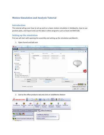
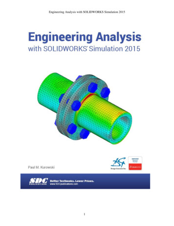
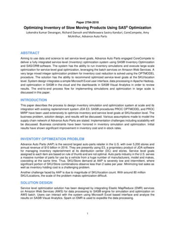
List of Figures1Fully assembled towfish out of the water . . . . . . . . . . . . . . . .12Two-part towing arrangement . . . . . . . . . . . . . . . . . . . . . .23A sketch of the towfish taking measurements . . . . . . . . . . . . . .34Top and side views of the towfish and its components [20] . . . . . . .45Sensor used to make fluid velocity measurements . . . . . . . . . . . .56Location of the body and inertial coordinate frames on the towfish [20] 107The body angular momentum related to the inertial frame . . . . . .8The U.S. Airship Akron 1/40-scale model drag coefficient data versuspitch angle with a quadratic fit . . . . . . . . . . . . . . . . . . . . .91821The U.S. Airship Akron 1/40-scale model lift coefficient data versuspitch angle with a linear and a quadratic fit . . . . . . . . . . . . . .2210Hydrodynamic angles . . . . . . . . . . . . . . . . . . . . . . . . . . .2311The U.S. Airship Akron 1/40-scale model pitching moment coefficientdata versus pitch angle with a linear fit. . . . . . . . . . . . . . . .2512Towing configuration . . . . . . . . . . . . . . . . . . . . . . . . . . .3013Free-body diagram of the towfish . . . . . . . . . . . . . . . . . . . .3114Free-body diagram of the towfish at equilibrium . . . . . . . . . . . .3515Diagram for a differential element of the cable . . . . . . . . . . . . .3616Definition of the length of a differential element of the cable . . . . .3717Cable profiles for speeds between 3.3 ft/s to 10.3 ft/s . . . . . . . . .39xvii
18Cable profiles zoomed in at the end attached to the depressor . . . .19The quadratic fit of the force versus the velocity plotted with the original data . . . . . . . . . . . . . . . . . . . . . . . . . . . . . . . . . .2043A diagram showing how the system has been modeled in comparisonto the actual system . . . . . . . . . . . . . . . . . . . . . . . . . . .2342The polynomial fit of the diagonal distance versus the velocity plottedwith the original data . . . . . . . . . . . . . . . . . . . . . . . . . . .2241The diagonal distance measurement between the towfish nose and thedepressor . . . . . . . . . . . . . . . . . . . . . . . . . . . . . . . . . .214044Cable coordinate frame where the x-axis points from the towfish noseto the depressor . . . . . . . . . . . . . . . . . . . . . . . . . . . . . .4624Motion of the depressor, minus the steady component in the x-direction 4825The angles that define the cable reference frame . . . . . . . . . . . .4926The PID controller structure [20] . . . . . . . . . . . . . . . . . . . .5327Variation in pitch angle at a velocity of 3.3 ft/s (1 m/s) for a range ofsea states . . . . . . . . . . . . . . . . . . . . . . . . . . . . . . . . .28Variation in pitch angle at a velocity of 6.6 ft/s (2 m/s) for a range ofsea states . . . . . . . . . . . . . . . . . . . . . . . . . . . . . . . . .293163Variation in pitch angle at a velocity of 9.8 ft/s (3 m/s) for a range ofsea states . . . . . . . . . . . . . . . . . . . . . . . . . . . . . . . . .306264Times exceeding the desired pitch angle range of plus or minus 0.5degrees versus Sea Sate at a velocity of 9.8 ft/s over 100 seconds . . .65Variation in roll angle at sea state 3 for a range of velocity values . .66xviii
32Variation in pitch angle at sea state 3 for a range of velocity values .33Variation in pitch angle for a towing velocity of 3.3 ft/s for four differentcg locations . . . . . . . . . . . . . . . . . . . . . . . . . . . . . . . .3469Variation in pitch angle for a towing velocity of 9.8 ft/s for four differentcg locations . . . . . . . . . . . . . . . . . . . . . . . . . . . . . . . .3668Variation in pitch angle for a towing velocity of 6.6 ft/s for four differentcg locations . . . . . . . . . . . . . . . . . . . . . . . . . . . . . . . .356770Times exceeding the desired pitch angle range of plus or minus 0.5degrees versus cg position at a towing speed of 9.8 ft/s for 100 seconds where Xcg1 [0; 0; 1] inches,Xcg2 [2; 0.26; 0.36] inches,Xcg3 [0.145; 0.216; 0.46] inches and Xcg4 [0; 1; 1] inches. . . . . . . . .37Variation in roll angle for a towing velocity of 3.3 ft/s for four differentcg locations . . . . . . . . . . . . . . . . . . . . . . . . . . . . . . . .3875Variation in roll angle for a no controller versus a PID controller at atowing velocity of 6.6 ft/s . . . . . . . . . . . . . . . . . . . . . . . .4274Variation in pitch angle for no controller versus a PID controller at atowing velocity of 6.6 ft/s . . . . . . . . . . . . . . . . . . . . . . . .4173Variation in roll angle for a towing velocity of 9.8 ft/s for four differentcg locations . . . . . . . . . . . . . . . . . . . . . . . . . . . . . . . .4072Variation in roll angle for a towing velocity of 6.6 ft/s for four differentcg locations . . . . . . . . . . . . . . . . . . . . . . . . . . . . . . . .397176Variation in roll angle for no controller, a PID controller, and a PIDcontroller with a dead zone at a towing velocity of 6.6 ft/s . . . . . .xix77
43Variation in roll angle for no controller versus a PID controller with adead zone at a towing velocity of 6.6 ft/s. Note the scale on the y axisis 10 3 . . . . . . . . . . . . . . . . . . . . . . . . . . . . . . . . . . . .7844Top half of the hull constructed of fiberglass . . . . . . . . . . . . . .8045Half of the hull in the female mold . . . . . . . . . . . . . . . . . . .8146A rear view of the four fins attached to the hull . . . . . . . . . . . .8247Aluminum frame of the towfish [20] . . . . . . . . . . . . . . . . . . .8348Inside view of the Power Housing [20]. . . . . . . . . . . . . . . . .8449The power housing sitting in the Starboard mount [20] . . . . . . . .8550The inside of the computer housing [20]. . . . . . . . . . . . . . . .8651Electronics diagram [20] . . . . . . . . . . . . . . . . . . . . . . . . .8752Detailed diagram of the VADCP (units in inches ). *Adapted fromreference [20] . . . . . . . . . . . . . . . . . . . . . . . . . . . . . . .8853A view of the top hull with foam inside . . . . . . . . . . . . . . . . .8954A piece of foam that was constructed to fit between the inside of thetowfish hull and the outside of the frame . . . . . . . . . . . . . . . .9055The Benthos Datasonic PSA-916 altimeter . . . . . . . . . . . . . . .9056Towfish setup in the water tank to find the dry weight . . . . . . . .9157Towfish trim and ballast diagram . . . . . . . . . . . . . . . . . . . .9258The area in the nose of the towfish where C-Foam TP-24 was added59(adapted from [20]) . . . . . . . . . . . . . . . . . . . . . . . . . . . .96The limit sensor mount attached to the towfish frame . . . . . . . . .97xx
60A side view portraying how the sensor was weighed. Points A, B, andC denote where the scales were hung above the sensor to measure theweight of the sensor. . . . . . . . . . . . . . . . . . . . . . . . . . . .9961Closed-loop system for the towfish . . . . . . . . . . . . . . . . . . . . 11762Simulink block that describes the towfish system . . . . . . . . . . . . 11863Simulink block that limits the fin movement . . . . . . . . . . . . . . 11964Simulink block that develops the depressor motion . . . . . . . . . . . 11965Simulink block that describes the PID control . . . . . . . . . . . . . 12166PID controller block with the dead zone . . . . . . . . . . . . . . . . 12267A system that inputs the DMU pitch and roll measurements and outputs the corrected terms with respect to the body frame . . . . . . . 14468Simulink block that inputs the DMU pitch and roll measurements andoutputs them relative to the body frame . . . . . . . . . . . . . . . . 145xxi
List of Tables1Reynolds’ numbers over the operating velocity range for the towfish .332Data of sea states from the North Atlantic . . . . . . . . . . . . . . .563Dry and wet weight measurements for the fully assembled towfish . .924Period measurements without the fins . . . . . . . . . . . . . . . . . .945Pressure housing measurements . . . . . . . . . . . . . . . . . . . . .986Sensor measurements . . . . . . . . . . . . . . . . . . . . . . . . . . .99xxii
1IntroductionThe goal of this project is to create a towed sensor platform that can hold a fivebeam acoustic Doppler current profiler (VADCP) used to measure small-scale oceanturbulence. The towfish design has a streamlined body, two fixed vertical stabilizersand two independently actuated stern planes. The fully assembled towfish out of thewater can be seen in Figure 1.Vertical FinsSensor HeadHullStern PlaneFigure 1: Fully assembled towfish out of the waterPerformance specifications for the towfish include the ability to operate at depthsof 660 feet ( 200 m) and speeds from 2 to 6 knots ( 3 ft/s to 10 ft/s). Toallow accurate measurements to be made by the sensor to observe small-scale oceanturbulence in a vertical column, the towfish also needs to maintain plus or minus onedegree of attitude in pitch and roll. For recovery purposes, the towfish is designed tobe 5 percent buoyant.1
1.1System configurationThe towfish for this project was designed as a two-part tow where an umbilical cableruns from the research vessel to the towfish, with a depressor fastened along the cable;see Figure 2. The section of the cable from the ship to the depressor is known asthe “main catenary” and the portion of the cable from the depressor to the towfishis labelled the “pigtail”.BoatTowfishMain CatenaryDepressorWeightPigtailFigure 2: Two-part towing arrangementThis design was developed with four fins to give the towfish more stability and theability to reject disturbances. This is necessary in order to make accurate measurements with the VADCP. The VADCP measures three components of fluid velocitythat scientists can use to observe small-scale ocean turbulence in a vertical column.Figure 3 shows a sketch of the towfish taking measurements.In order to make these measurements, the fins on the towfish are used to stabilizethe vehicle within plus or minus one degree of pitch and roll. If the fins are unable tomaintain the attitude in this range, the turbulence measurements will be corruptedand unusable. The two horizontal fins of the towfish are controlled by two servoactuators through a sprocket/chain assembly. The two vertical fins are fixed and thetop fin holds a VHF(very high frequency) pinger with a Xenon strobe light. Alongwith the VADCP, the towfish contains an on-board computer, an altimeter, a depth2
Figure 3: A sketch of the towfish taking measurementssensor, and an inertial measurement unit. The altimeter measures the distance thetowfish is from the bottom of the ocean. The depth sensor measures the depth of thetowfish relative to the surface. The research vessel which tows the system, suppliesAC power which is converted locally into 144, 48 and 12 volts DC to power the variousonboard components. The power converters, computer, and a tilt sensor are enclosedin two watertight pressure housings that were designed to fit inside of the aluminumframe of the towfish.The towfish was originally designed by Eric Schuch as described in his Masters thesis[20]. Figure 4 shows the original design of the towfish. A detailed description of thetowfish components has been included in Section 5 of this thesis.1.2Literature reviewTraditionally, ocean turbulence has been measured by dropping a tethered instrumentat a point in the ocean, letting it fall to a specified depth and then retrieving theinstrument. This type of data collection takes a lot of time. Recently, scientists havebegun to measure fluid velocity using acoustic doppler current profilers (ADCPs),3
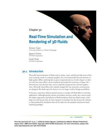
Figure 4: Top and side views of the towfish and its components [20]which give them data at a grid of points in a vertical plane. Old Dominion University’s Center for Coastal Physical Oceanography (CCPO) has a five-beam ADCP thatcan produce maps of the turbulence quantities such as vertical momentum stresses,turbulent kinetic energy, and the dissipation rate. The vertical shear and the meancurrent can also be measured with this sensor. A VADCP gives scientists the abilityto map turbulence in offshore environments by identifying pockets of turbulence inthe ocean quickly. The towfish can look for turbulent spots at a moderate speed andthen when a turbulent area is found, it can gather higher resolution data at a lowerspeed. The VADCP was custom built by RD Instruments and is a one-of-a-kind sensor. The five beams of this sensor run at 1200 kHz. Figure 5 shows a photograph ofthe actual sensor.The VADCP measures three components of fluid velocity. Four beams in a tetrahedral arrangement measure two components of velocity and the fifth beam providesthe third velocity component. To accurately resolve small-scale ocean turbulence,the fifth beam must be precisely aligned with the local direction of gravity. The4
Figure 5: Sensor used to make fluid velocity measurementsturbulent fluctuations are orders of magnitude larger in the lateral direction; a smallmisalignment of the sensor can irreversibly corrupt the data.A few different approaches were considered for carrying the VADCP. These differentapproaches included remotely operated vehicles (ROVs), autonomous underwater vehicles(
Jx Moment of inertia of the towfish about the body x axis Jxy The product of inertia about the x-y axes Jxz The product of inertia about the x-z axes Jy Moment of inertia of the towfish about the body y axis Jyz The product of inertia about the y-z axes Jz Moment of inertia of the towfish about the body z axis J0 Rotational rigid body .