Transcription
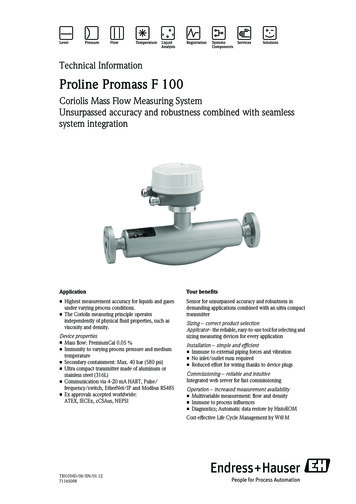
cesSpecial DocumentationProline Promass 300Functional Safety ManualCoriolis flowmeterApplicationYour benefitsMonitoring of the maximum and/or minimum flow or densityin systems which are required to comply with the particularfunctional safety requirements of IEC 61508. Use for flow monitoring up to SIL 2 (single-channelarchitecture) or SIL 3 (multi-channel architecture withhomogeneous redundancy) - independently assessed andcertified by TÜV in accordance with IEC 61508 Alternatively also suitable for density monitoring Measurement is virtually independent of the processproperties Permanent self-monitoring Easy installation and commissioning Integrated proof-testing Heartbeat verification for the documentation of diagnosticchecks in accordance with IEC 61511The measuring device fulfills the requirements concerning: Functional safety as per IEC 61508 Explosion protection (depending on the version) Electromagnetic compatibility as per IEC 61326-3-2 andNAMUR recommendation NE 21 Electrical safety as per IEC 61010-1
Proline Promass 300Table of contentsManufacturer's Declaration . . . . . . . . . . . . . . . . . . .3Safety-related characteristic values . . . . . . . . . . . . . . . . . . 4Useful lifetime of electric components . . . . . . . . . . . . . . . . 6Document information . . . . . . . . . . . . . . . . . . . . . . . 6Document function . . . . . . . . . . . . . . . . . . . . . . . . . . . .Using this document . . . . . . . . . . . . . . . . . . . . . . . . . . .Symbols used . . . . . . . . . . . . . . . . . . . . . . . . . . . . . . . .Supplementary device documentation . . . . . . . . . . . . . . . .6667Permitted device types . . . . . . . . . . . . . . . . . . . . . . . 9SIL label on the nameplate . . . . . . . . . . . . . . . . . . . . . .10Safety function . . . . . . . . . . . . . . . . . . . . . . . . . . . . 10Definition of the safety function . . . . . . . . . . . . . . . . . . . 10Restrictions for use in safety-related applications . . . . . . . 10Use in protective systems . . . . . . . . . . . . . . . . . . . . 12Device behavior during operation . . . . . . . . . . . . . . . . . . 12Parameter configuration for safety-related applications . . . 13Proof-testing . . . . . . . . . . . . . . . . . . . . . . . . . . . . . . . 20Life cycle . . . . . . . . . . . . . . . . . . . . . . . . . . . . . . . . . 23Requirements for the personnel . . . . . . . . . . . . . . . . . . .Installation . . . . . . . . . . . . . . . . . . . . . . . . . . . . . . . . .Commissioning . . . . . . . . . . . . . . . . . . . . . . . . . . . . . .Operation . . . . . . . . . . . . . . . . . . . . . . . . . . . . . . . . .Maintenance . . . . . . . . . . . . . . . . . . . . . . . . . . . . . . .Repairs . . . . . . . . . . . . . . . . . . . . . . . . . . . . . . . . . . .Modification . . . . . . . . . . . . . . . . . . . . . . . . . . . . . . . .Decommissioning . . . . . . . . . . . . . . . . . . . . . . . . . . . .2323242424242424Appendix . . . . . . . . . . . . . . . . . . . . . . . . . . . . . . . .25Structure of the measuring system . . . . . . . . . . . . . . . . .Verification or calibration . . . . . . . . . . . . . . . . . . . . . . .Notes on the redundant use of multiple sensors . . . . . . . .Version history . . . . . . . . . . . . . . . . . . . . . . . . . . . . . .225262626Endress Hauser
Proline Promass 300Manufacturer's DeclarationA0031602-ENEndress Hauser3
Proline Promass 300Safety-related characteristicvaluesGeneralDevice designation and permitted versions8A3B (Promass A 300)8E3B (Promass E 300)8F3B (Promass F 300)8H3B (Promass H 300)8I3B (Promass I 300)8O3B (Promass O 300)8P3B (Promass P 300)8Q3B (Promass Q 300)8S3B (Promass S 300)8X3B (Promass X 300)Order code for "Output; input 1": Option BA "4-20mA HART" Option BB "4-20mA Wireless HART" Option CA "4-20mA HART Ex-i" Option CB "4-20mA Ex-i Wireless HART"Order code for "Output; input 2":All optionsOrder code for "Output; input 3":All optionsOrder code for "Additional approval":Option LA "SIL"Safety-related output signal4 to 20 mA (output; input 1)Error current 3.6 mA or 21 mAAssessed measured variable/functionMonitoring of mass flow, volume flow or densitySafety function(s)Min., Max., RangeDevice type according to IEC 61508-2 Type A Type BOperating mode Low Demand Mode High Demand ModeValid hardware version (main electronics)From delivery date August 2, 2016Valid firmware version01.00.zz and higher (HART; from delivery date August 2, 2016)Safety manualSD01727DType of assessment(only 1 version can be selected) Complete HW/SW assessment in the context of development including FMEDA and changeprocess according to 61508-2, 3 Continuous Mode 1) Assessment of evidence for proven-in-use HW/SW including FMEDA and change processaccording to 61508-2, 3 Analysis of HW/SW field data for evidence of "prior use" according to IEC 61511 Assessment by FMEDA according to IEC 61508-2 for devices without softwareAssessment by (including Report No. FMEDAdata source)TÜV Rheinland Industrie Service GmbH – Certificate No. 968/FSP 1306.00/16Test documentsDevelopment documents, test reports, data sheetsSIL integritySystematic safety integrityHardware safety integrity SIL 2 capable SIL 3 capableSingle-channel service (HFT 0) SIL 2 capable SIL 3 capableMulti-channel service (HFT 1) SIL 2 capable SIL 3 capableFMEDASafety function(s)Min., Max., RangeOption BA, BBOption CA, CBλDU2)121 FIT117 FITλDD2)1366 FIT1346 FIT4Endress Hauser
Proline Promass 300λSU 2)871 FIT1067 FIT1308 FIT1295 FIT97 %97 %PFDavg for T1 1 year(single-channel architecture)5.3 · 10-45.1 · 10-4PFDavg for T1 4 years 3)(single-channel architecture)2.1 · 10-32.0 · 10-3PFH6.1 · 10-85.8 · 10-8λSD2)SFF - Safe Failure Fraction3)PTC 4)Up to 98 %MTBFtot5)66 yearsDiagnostic test intervalFault response timeProcess safety time6)30 min7)30 s8)50 hRecommended test interval T1MTTFd9)55 years4 years77 years78 yearsNoteThe measuring device has been developed for use in "Low Demand" and "High Demand" mode.Explanation Our in-house quality management system saves information on safety-related systematic errors that will become known in the future.1)2)3)4)5)6)7)8)9)No continuous operation as per IEC 61508: 2011 (section 3.5.16)FIT Failure In Time, number of failures per 109 hValid for averaged ambient temperatures up to 40 C (104 F) in accordance with general standard for devices with SIL capability.PTC Proof Test Coverage (diagnostic coverage achieved by device failure detection during manual proof testing)This value takes into account all failure types of the electronic components as per Siemens SN29500All diagnostic functions are carried out at least once during this time.Maximum time between fault detection and fault response.The process safety time amounts to the diagnostic test interval * 100 (calculation as per IEC 61508).MTTFd as per ISO 13849/IEC 62061 also includes soft errors (sporadic bit errors in data memories).Endress Hauser5
Proline Promass 300Useful lifetime of electriccomponentsThe established failure rates of electrical components apply for a useful lifetime of 12 years as perIEC 61508-2: 2010, Section 7.4.9.5, Note 3.The device's year of manufacture is coded in the first character of the serial number ( table below).Example: serial number L5ABBF02000 year of manufacture 2016ASCII characterMeaningASCII characterMeaningASCII 2M2017T2022H2013N2018V2023J2014P2019W2024Document informationDocument functionThe document is part of the Operating Instructions and serves as a reference for application-specificparameters and notes. General information about functional safety: SIL General information about SIL is available:In the Download Area of the Endress Hauser Internet site: www.de.endress.com/SILUsing this documentInformation on the document structureFor the arrangement of the parameters as per the Operation menu, Setup menu, Diagnosticsmenu, along with a short description, see the Operating Instructions for the deviceFor information about the operating philosophy, see the "Operating philosophy" chapter in thedevice's Operating InstructionsSymbols usedSafety symbolsSymbolMeaningDANGERDANGER!This symbol alerts you to a dangerous situation. Failure to avoid this situation willresult in serious or fatal injury.WARNINGWARNING!This symbol alerts you to a dangerous situation. Failure to avoid this situation canresult in serious or fatal injury.CAUTIONCAUTION!This symbol alerts you to a dangerous situation. Failure to avoid this situation canresult in minor or medium injury.NOTICENOTE!This symbol contains information on procedures and other facts which do not result inpersonal injury.Symbols for certain types of informationSymbolMeaningTipIndicates additional information.Reference to documentationA6Reference to pageEndress Hauser
Proline Promass 300SymbolMeaningReference to graphicNotice or individual step to be observed1. , 2. , 3. Series of stepsResult of a stepOperation via local displayOperation via operating toolWrite-protected parameterSymbols in graphicsSymbolMeaning1, 2, 3 .Item numbersA, B, C, .ViewsA-A, B-B, C-C, .Supplementary devicedocumentationSectionsFor an overview of the scope of the associated Technical Documentation, refer to the following: The W@M Device Viewer : Enter the serial number from the nameplate(www.endress.com/deviceviewer) The Endress Hauser Operations App: Enter the serial number from the nameplate or scan the2-D matrix code (QR code) on the nameplate.Standard documentationOperating InstructionsMeasuring deviceDocumentation codePromass A 300BA01482DPromass E 300BA01484DPromass F 300BA01485DPromass H 300BA01486DPromass I 300BA01487DPromass O 300BA01488DPromass P 300BA01489DPromass Q 300BA01490DPromass S 300BA01491DPromass X 300BA01492DDescription of Device ParametersEndress HauserMeasuring deviceDocumentation codePromass 300GP01057D7
Proline Promass 300Technical InformationMeasuring deviceDocumentation codePromass A 300TI01270DPromass E 300TI01272DPromass F 300TI01221DPromass H 300TI01273DPromass I 300TI01274DPromass O 300TI01275DPromass P 300TI01276DPromass Q 300TI01277DPromass S 300TI01278DPromass X 300TI01279DSupplementary device-dependent documentationSafety InstructionsContentsDocumentation codeATEX/IECEx Ex d/Ex deXA01414DATEX/IECEx Ex ecXA01514DcCSAus XPXA01515DcCSAus Ex d/ Ex deXA01516DcCSAus Ex nAXA01517DINMETRO Ex d/Ex deXA01518DINMETRO Ex ecXA01519DNEPSI Ex d/Ex deXA01520DNEPSI Ex nAXA01521DRemote display and operating module DKX001ContentsDocumentation codeATEX/IECEx Ex iXA01494DATEX/IECEx Ex ecXA01498DcCSAus ISXA01499DcCSAus Ex nAXA01513DINMETRO Ex iXA01500DINMETRO Ex ecXA01501DNEPSI Ex iXA01502DNEPSI Ex nAXA01503DSpecial Documentation8ContentsDocumentation codeInformation on the Pressure Equipment DirectiveSD01614DRemote display and operating module DKX001SD01763DEndress Hauser
Proline Promass 300Installation InstructionsContentsDocumentation codeInstallation Instructions for sparepart setsFor an overview of the accessories available for order, see the OperatingInstructions for the devicePermitted device typesThe details pertaining to functional safety in this manual relate to the device versions listed belowand are valid as of the specified software and hardware versions. Unless otherwise specified, allsubsequent versions can also be used for safety functions. A modification process according to IEC61508 is applied for any device modifications.Feature DesignationOption selected–Order code8A3B (Promass A 300)8E3B (Promass E 300)8F3B (Promass F 300)8H3B (Promass H 300)8I3B (Promass I 300)8O3B (Promass O 300)8P3B (Promass P 300)8Q3B (Promass Q 300)8S3B (Promass S 300)8X3B (Promass X 300)000Nominal diameterAll010Approval; transmitter sensorAll015Power supplyAll020Output; input 1021Output; input 2All022Output; input 3All030Display; OperationAll040HousingAll050Electrical connectionAll060Measuring tube mat., wetted surfaceAll070Process connectionAll080Calibration flowAll480Device modelAll500Display operating languageAll520Sensor optionAll530Customer-specific configurationAllApplication PackageAllSuitability for custody transfer measurementAll570ServiceAll580Test, certificateAll590Additional approvalLA ( SIL) 3)610Accessory mountedAll620Accessory enclosedAll540550Endress Hauser1)2) Option BA "4-20mA HART"Option BB "4-20mA Wireless HART"Option CA "4-20mA HART Ex-i"Option CB "4-20mA Ex-i Wireless HART"9
Proline Promass 300Feature DesignationOption selected850Firmware versionFirmware with SIL capability, e.g. 01.00.zz (HART)895MarkingAll1)2)3)In devices with several outputs, only current output 1 (terminals 26 and 27) is suitable for safety functions.The other outputs can, if necessary, be connected for non-safety-oriented purposes.Only for devices with approval for custody transferAdditional selection of further approvals is possible.SIL label on the nameplateOrder code:Ser. no.:Ext. ord. cd.:iiDate:1A00314731SIL logoSafety functionDefinition of the safetyfunctionThe measuring device's permitted safety functions are: Monitoring of a maximum or minimum mass flow or a mass flow range for liquid or gaseousmedia Monitoring of a maximum or minimum volume flow or a volume flow range for liquid media Monitoring of a maximum or minimum density or a density range for liquid mediaThe safety functions are based on the simultaneous, continuous measurement of the mass flow andthe density of a liquid.Safety-related output signalThe measuring device's safety-related signal is the 4–20 mA analog output signal (output; input 1).All safety measures refer to this signal exclusively.In devices with several outputs, only current output 1 (terminals 26 and 27) is suitable for safetyfunctions. The other outputs can, if necessary, be connected for non-safety-oriented purposes.The safety-related output signal is fed to a downstream automation system where it is monitored forthe following: Overshooting and/or undershooting of a specified limit value for the flow or the density of themedium The occurrence of a fault: e.g. error current ( 3.6 mA, 21 mA), interruption or short-circuit ofthe signal lineRestrictions for use in safetyrelated applicationsDo not exceed the specifications indicated in the device documentation: 7.Dangerous undetected failures in this scenarioAn incorrect output signal that deviates from the value specified in the Operating Instructions but isstill in the range of 4 to 20 mA, is considered a dangerous, undetected failure.10Endress Hauser
Proline Promass 300Detailed information concerning measured errors:For detailed information on the maximum measured error, see the Operating Instructions forthe device 7Suitability of the measuring device1.Carefully select the nominal diameter of the measuring device in accordance with theapplication's expected flow rates. The maximum flow rate during operation must not exceed the specified maximum valuefor the sensor.2.In safety-related applications, it is advisable to select the limit value for monitoring a minimumflow such that this limit is at least twice the smallest specified flow that can still be measured,with the actual medium and the selected nominal diameter. For detailed information, see the Technical Information for the device 83.In safety-related applications, it is also advisable to select a limit value for monitoring theminimum flow that is not less than 5 % of the specified maximum value of the sensor.NOTICEUse the measuring device according to the specifications.‣ Pay attention to the medium properties and the environmental conditions.‣ Carefully follow instructions pertaining to critical process situations and installation conditions.Detailed information on: Installation Electrical connection Medium properties Environment ProcessOperating Instructions and Technical Information for the device 7LCAUTIONPay particular attention to the following:‣ It is essential to avoid the occurrence of entrained air, cavitation or two-phase mixtures in themeasuring tube which can result in a higher measuring uncertainty.‣ In the case of liquids with a low boiling point or liquids in suction lines, it is important to ensurethat the pressure does not drop below the vapor pressure and that the liquid does not start toboil.‣ Please ensure that there is never any outgassing of the gases naturally contained in many liquids.Sufficiently high system pressure prevents the occurrence of these effects.‣ Make sure that cavitation does not occur as it can affect the operating life of the measuringtubes.‣ If gaseous media are used, turbulences can occur at high flow velocity rates, e.g. if valves arehalf-closed. This can cause the measured values to fluctuate.‣ Avoid applications that cause buildup, corrosion or abrasion in the measuring tube.No special measures need to be taken into consideration for single-phase, liquid media withproperties similar to water.Detailed information on the suitability of the measuring device for safety-related operation isavailable from your Endress Hauser sales center.Information on measured errorsWhen the measured value is transmitted via the 4–20 mA current output, the measuring device'srelative measured error is made up of the contribution of the digitally determined measured valueand the accuracy of the analog current output. These contributions, which are listed in the devicedocumentation, apply under reference operating conditions and can depend on the sensor versionordered. If process or ambient conditions are different, there are additional contributions, e.g.temperature or pressure, which are also listed.For detailed information on calculating the measured error, see the Technical Information forthe device 8Guidelines for minimal measured errors:1.Endress HauserIn the event of high process pressure:Set the typical process pressure in the measuring device.11
Proline Promass 3002.If measuring the mass flow or volume flow:Experience shows that zero point adjustment is advisable only in special cases: To achieve maximum measuring accuracy even with low flow ratesUnder extreme process or operating conditions (e.g. very high process temperatures orvery high-viscosity fluids)3.The volume flow is calculated in the device from the mass flow and density. For minimummeasured error for the measured volume flow:Perform field density calibration under process conditions.4.Limit value monitoring: Depending on the process dynamics, the current value of the unfiltered4–20 mA output signal can temporarily exceed the specified tolerance range.The device can optionally provide damping of the current output via a parameter that onlyaffects the measured value output. Device-internal diagnostics or the outputting of an error current ( 3.6 mA, 21 mA) arenot affected by this damping.Power supply to the 4–20 mA current outputOvervoltages at the 4–20 mA current output (passive, output; input 1) - caused by a fault in thesupply unit for example - can result in a leak current in the device's input protection circuit. This maylead to falsification of the output signal by more than the specified error or the minimum errorcurrent (3.6 mA) can no longer be set due to the leak current.‣ Use a 4–20 mA power supply unit with either voltage limitation or voltage monitoring.NOTICEThe safety-related connection values depend on the Ex approval.‣ Pay attention to the safety-related connection values.For detailed information on the connection values, see the "Safety Instructions" documentation 8HART communicationThe measuring device also communicates via HART or WirelessHART in the SIL mode. Thiscomprises all the HART features with additional device information.NOTICEThe measuring device's safety-related signal is the 4–20 mA analog output signal (output;input 1).All safety measures refer to this signal exclusively.‣ Please note the following: 10.NOTICEWhen the SIL locking code is entered, the device parameters that affect the safety-relatedoutput signal are locked and write-protected. It is still possible to read the parameters.When SIL locking is enabled, restrictions apply on all communication options, such as the serviceinterface (CDI-RJ45), HART protocol and WirelessHART protocol, local display and WLAN.‣ Deactivation of the SIL mode 19.Use in protective systemsDevice behavior duringoperationDevice behavior during power-upOnce switched on, the device runs through a start-up phase. The current output is set to errorcurrent during this time. This current is 3.6 mA in the initial seconds of this start-up phase.No communication with the device is possible via the interfaces during the start-up phase. After thestart-up phase the device switches to the normal mode (measuring operation).Behavior of device during operationThe device outputs a current value which corresponds to the measured value to be monitored. Thisvalue must be monitored and processed further in an attached automation system.12Endress Hauser
Proline Promass 300Device behavior in safety function demand modeDepending on the setting of the Failure mode parameter, the current is as follows in demand mode: For Min. option: 3.6 mA For Max. option: 21 mADevice behavior in event of alarms and warningsThe output current on alarm can be set to a value 3.6 mA or 21 mA.In some cases (e.g. a cable open circuit or faults in the current output itself, where it is not possible toset the error current 21 mA) output currents of 3.6 mA occur irrespective of the configured errorcurrent.In some other cases (e.g. short circuit of cabling), output currents of 21 mA occur irrespective ofthe configured error current.For alarm monitoring, the downstream automation system must be able to recognize both maximumalarms ( 21 mA) and minimum alarms ( 3.6 mA).Alarm and warning messagesThe alarm and warning messages output on the device display or in the operating tool in the form ofdiagnostic events and the associated event text are additional information.For detailed information on diagnostic events, see the Operating Instructions for the device 7NOTICEWhen SIL mode is activated, additional diagnostics are activated.If a diagnostic event occurs and the locked SIL mode is deactivated, the error message remains whilethe error persists, even if the diagnostic event is no longer active in the unlocked state.‣ In this case, the device must be disconnected briefly from the power supply .‣ When the device is then restarted, a self-check is carried out, and the diagnostics event is resetwhere applicable.Parameter configuration forsafety-related applicationsCalibration of the measuring pointThe measuring point is calibrated via the operating interfaces. A wizard guides you systematicallythrough all the submenus and parameters that have to be set for configuring the measuring device.For detailed information on operation options, see the Operating Instructions for the device 7For detailed information on the configuration of the measuring device, see the OperatingInstructions for the device and the "Description of Device Parameters" documentation 7To activate the SIL mode, the device must run through a confirmation sequence. While runningthrough this sequence, critical parameters are either set automatically by the device to standardvalues or transferred to the local display/operating tool to enable verification of the setting. Oncompletion of parameter configuration, the SIL mode of the device must be enabled with a SILlocking code.Availability of the SIL mode functionNOTICEThe SIL confirmation sequence is only visible on the local display and in the operating tools fordevices with the order code for "Additional approval", option LA "SIL".‣ For this reason, the SIL mode can also only be activated on these measuring devices.‣ If the LA "SIL" option was ordered for the flowmeter ex works, this function is available when themeasuring device is delivered to the customer. Access is via the operating interfaces of themeasuring device.‣ If the order option cannot be accessed in the measuring device, the function cannot be retrofittedduring the life cycle of the device. If you have any questions please contact your Endress Hauserservice or sales organization.Ways to check function availability in the measuring device:Using the serial number:W@M Device viewer 1) Order code for "Additional approval", option LA "SIL"1)www.endress.com/deviceviewerEndress Hauser13
Proline Promass 300Detailed information concerning the SIL label: Permitted device types 9 SIL label on the transmitter nameplate 10Overview of the SIL modeThe SIL mode enables the following steps:1.Makes sure that the preconditions are met. The measuring device checks whether the user has correctly configured a predefined set ofparameters for the safety function.If the result is positive, the device continues with the activation of the SIL mode.If the result is negative, the sequence is not permitted or is aborted, and the device doesnot continue with the activation of the SIL mode.2.Automatically switches a predefined set of parameters to the default values specified by themanufacturer. This parameter set ensures that the flowmeter works in the safety mode.3.Guides the user through the preconfigured parameters for checking. This ensures that the user actively checks all the important pre-settings.4.Activates write protection for all the relevant parameters in the SIL mode.All this ensures that the parameter settings that are required for the safety function are configuredcorrectly. (These settings cannot be circumvented either deliberately or by accident.)Locking a SIL deviceWhen locking a SIL device, all safety-related parameter settings are shown to the operatorindividually and must be confirmed explicitly. Parameter settings not permitted in the locked SILmode are reset to their default values where necessary. A SIL locking code is then entered to lock thedevice software to ensure that parameters cannot be changed. Non-safety-related parametersremain unchanged.14Endress Hauser
Proline Promass 300NOTICEOnce the SIL device has been locked, the process-related parameters are write protected, andthereby locked, for security reasons.It is still possible to read the parameters. When SIL locking is enabled, restrictions apply on allcommunication options, such as the service interface, HART protocol and WirelessHART protocol,local display and WLAN.‣ Follow the specified locking sequence.1.Check preconditions. SetupCurrent output 1Select mediumPressurecompensation Offor Fixed valueAssigncurrent output 1 Mass flow* or Vol. flow* or Density*Current span 4.20 mAor 4.20 mA NAMUR or 4.20 mA USFailure mode Min. or Max.* . unit user-defined unitPartial filledpipe detectionPartial filledpipe detectionAssignprocess variableAssignprocess variable Offor Mass flow or Vol. flow Offor DensityA0015325-EN2.In the Setup menu Advanced setup submenu, select the SIL confirmation wizard.3.Select Set write protection parameter.4.Enter the SIL locking code 7452. The device first checks the preconditions listed under item 1.NOTICEIf these preconditions are not met, the message "SIL preparation failed" appears on thedisplay along with the parameter that failed to meet the preconditions under 1.The SIL confirmation sequence is not continued.‣ Check preconditions.If the conditions are met, the message "SIL preparation finished" appears on the display.Once the preconditions have been met, the device automatically switches the following parametersto safety-oriented settings:Endress Hauser15
Proline Promass 300SetupCurrent output 1Partial filledpipe detectionMeasuring mode(4 mA value)Response timepart. filled p. d. Forward flow 0A0015326-ENDiagnosticsSimulationAssign simulat.process variableSimulationcurrent output 1 Off OffA0015327-ENThe diagnostic behavior is set in such a way that the measuring device is set to the safe state whenan error occurs. This means that the diagnostic messages listed in the graphic are set to alarm andthe current output adopts the configured failsafe mode rDiagnostic no.046Diagnostic no.140, 274Diagnostic no.374Diagnostic no.830, 831Diagnostic no.834, 835Diagnostic no.913 AlarmA0031622-EN 16Diagnostic message 046 Sensor limit exceededDiagnostic message 140 Sensor signalDiagnostic message 274 Main electronic failureDiagnostic message 374 Sensor electronic (ISEM) faultyDiagnostic message 830 Sensor temperature too highDiagnostic message 831 Sensor temperature too lowDiagnostic message 834 Process temperature too highDiagnostic message 835 Process temperature too lowDiagnostic message 913 Medium unsuitableEndress Hauser
Proline Promass ampingFlowoverride 0 0 adjustmentMass flowoffsetMass flowfactorVolume flowoffsetVolume flowfactorDensity offsetDensity factor 0 1 0 1 0 turemode InternalmeasuredvalueA0031477-ENEndress Hauser17
Proline Promass 300ExpertOutputCommunicationCurrentoutput 1HARTconfigurationStart-upmodeHARTaddress Min. 0A0015328-ENTo check that values are displayed correctly, the following string appears on the device display oroperating tool: 0123456789 -.5.The user must confirm that the values are displayed correctly. The device displays the current settings for the following parameters one after another forthe user to confirm each of them:InstallationdirectionAssigncurrent outputCurrent spanSignal mode4 mA value20 mA valueDampingFailure modeMediumGas typeReference1)sound velocityTemp. coeff.1)sound velocityPartial filledpipe detectionLow valuepart. filled pipe det.High valuepart. filled pipe det.Max. dampingpart. filled pipe det.Assignlow f
080 Calibration flow All 480 Device model All 500 Display operating language All 520 Sensor option All 530 Customer-specific configuration All 540 Application Package All 550 2) Suitability for custody transfer measurement All 570 Service All 580 Test, certificate All 590 Additional approval LA ( SIL) 3)
