Transcription
Technical InformationProline Promass 80F, 83FCoriolis Mass Flow Measuring SystemThe universal and multivariable flowmeter for liquids and gasesApplicationThe Coriolis measuring principle operates independentlyof the physical fluid properties, such as viscosity anddensity. Extremely accurate measurement of liquids and gasessuch as oils, lubricants, fuels, liquefied gases, solvents,foodstuffs and compressed gases Fluid temperatures up to 350 C ( 662 F) Process pressures up to 100 bar (1450 psi) Mass flow measurement up to2200 t/h (80840 lb/min)Approvals for hazardous area: ATEX, FM, CSA, TIIS, IECEx, NEPSIApprovals in the food industry/hygiene sector: 3A, FDA, EHEDGConnection to all common process control systems: HART, PROFIBUS DP/PA, FOUNDATION Fieldbus,MODBUSRelevant safety aspects: Secondary containment up to 40 bar (580 psi),Pressure Equipment Directive, AD 2000 SIL-2 Purge connections or rupture disk (optional)TI101D/06/en/10.0971104046Your benefitsThe Promass measuring devices make it possibleto simultaneously record several process variables(mass/density/temperature) for various processconditions during measuring operation.The Proline transmitter concept comprises: Modular device and operating concept resultingin a higher degree of efficiency Software options for batching and concentrationmeasurement for extended range of application Diagnostic ability and data back-up for increasedprocess qualityThe Promass sensors, tried and tested in over 100000applications, offer: Best performance due to PremiumCal Multivariable flow measurement in compact design Insensitivity to vibrations thanks to balancedtwo-tube measuring system Immune from external piping forces dueto robust design Easy installation without taking inlet and outletruns into consideration
Proline Promass 80F, 83FTable of contentsFunction and system design. . . . . . . . . . . . . . . . . . . . . 3Operating conditions: Process . . . . . . . . . . . . . . . . . . 22Measuring principle . . . . . . . . . . . . . . . . . . . . . . . . . . . . . . . . . . . 3Measuring system . . . . . . . . . . . . . . . . . . . . . . . . . . . . . . . . . . . . . 4Medium temperature range . . . . . . . . . . . . . . . . . . . . . . . . . . . .Medium pressure range (nominal pressure) . . . . . . . . . . . . . . . .Rupture disk . . . . . . . . . . . . . . . . . . . . . . . . . . . . . . . . . . . . . . .Limiting flow . . . . . . . . . . . . . . . . . . . . . . . . . . . . . . . . . . . . . . .Pressure loss . . . . . . . . . . . . . . . . . . . . . . . . . . . . . . . . . . . . . . .Input . . . . . . . . . . . . . . . . . . . . . . . . . . . . . . . . . . . . . . 6Measured variable . . . . . . . . . . . . . . . . . . . . . . . . . . . . . . . . . . . . 6Measuring range . . . . . . . . . . . . . . . . . . . . . . . . . . . . . . . . . . . . . . 6Operable flow range . . . . . . . . . . . . . . . . . . . . . . . . . . . . . . . . . . . 7Input signal . . . . . . . . . . . . . . . . . . . . . . . . . . . . . . . . . . . . . . . . . 7Output . . . . . . . . . . . . . . . . . . . . . . . . . . . . . . . . . . . . . 8Output signal . . . . . . . . . . . . . . . . . . . . . . . . . . . . . . . . . . . . . . . . 8Signal on alarm . . . . . . . . . . . . . . . . . . . . . . . . . . . . . . . . . . . . . 10Load . . . . . . . . . . . . . . . . . . . . . . . . . . . . . . . . . . . . . . . . . . . . . 10Low flow cutoff . . . . . . . . . . . . . . . . . . . . . . . . . . . . . . . . . . . . . 10Galvanic isolation . . . . . . . . . . . . . . . . . . . . . . . . . . . . . . . . . . . . 10Switching output . . . . . . . . . . . . . . . . . . . . . . . . . . . . . . . . . . . . 10Power supply . . . . . . . . . . . . . . . . . . . . . . . . . . . . . . . 11Electrical connection Measuring unit . . . . . . . . . . . . . . . . . . . . . 11Electrical connection, terminal assignment . . . . . . . . . . . . . . . . . 12Electrical connection Remote version . . . . . . . . . . . . . . . . . . . . . 13Supply voltage . . . . . . . . . . . . . . . . . . . . . . . . . . . . . . . . . . . . . . 13Cable entries . . . . . . . . . . . . . . . . . . . . . . . . . . . . . . . . . . . . . . . 13Remote version cable specification . . . . . . . . . . . . . . . . . . . . . . . 14Power consumption . . . . . . . . . . . . . . . . . . . . . . . . . . . . . . . . . . 14Power supply failure . . . . . . . . . . . . . . . . . . . . . . . . . . . . . . . . . . 14Potential equalization . . . . . . . . . . . . . . . . . . . . . . . . . . . . . . . . . 14Performance characteristics. . . . . . . . . . . . . . . . . . . . 15Reference operating conditions . . . . . . . . . . . . . . . . . . . . . . . . . . 15Maximum measured error . . . . . . . . . . . . . . . . . . . . . . . . . . . . . 15Repeatability . . . . . . . . . . . . . . . . . . . . . . . . . . . . . . . . . . . . . . . . 16Influence of medium temperature . . . . . . . . . . . . . . . . . . . . . . . . 17Influence of medium pressure . . . . . . . . . . . . . . . . . . . . . . . . . . . 17Design fundamentals . . . . . . . . . . . . . . . . . . . . . . . . . . . . . . . . . 17Operating conditions: Installation . . . . . . . . . . . . . . . 18Installation instructions . . . . . . . . . . . . . . . . . . . . . . . . . . . . . . . . 18Inlet and outlet runs . . . . . . . . . . . . . . . . . . . . . . . . . . . . . . . . . . 21Length of connecting cable . . . . . . . . . . . . . . . . . . . . . . . . . . . . . 21System pressure . . . . . . . . . . . . . . . . . . . . . . . . . . . . . . . . . . . . . 212222222323Mechanical construction . . . . . . . . . . . . . . . . . . . . . . 25Design, dimensions . . . . . . . . . . . . . . . . . . . . . . . . . . . . . . . . . .Weight . . . . . . . . . . . . . . . . . . . . . . . . . . . . . . . . . . . . . . . . . . .Material . . . . . . . . . . . . . . . . . . . . . . . . . . . . . . . . . . . . . . . . . . .Material load diagram . . . . . . . . . . . . . . . . . . . . . . . . . . . . . . . .Process connections . . . . . . . . . . . . . . . . . . . . . . . . . . . . . . . . . .2554555658Human interface . . . . . . . . . . . . . . . . . . . . . . . . . . . . 59Display elements . . . . . . . . . . . . . . . . . . . . . . . . . . . . . . . . . . . .Operating elements . . . . . . . . . . . . . . . . . . . . . . . . . . . . . . . . . .Language group . . . . . . . . . . . . . . . . . . . . . . . . . . . . . . . . . . . . .Remote operation . . . . . . . . . . . . . . . . . . . . . . . . . . . . . . . . . . . .59595959Certificates and approvals . . . . . . . . . . . . . . . . . . . . . 59CE mark . . . . . . . . . . . . . . . . . . . . . . . . . . . . . . . . . . . . . . . . . .C-Tick symbol . . . . . . . . . . . . . . . . . . . . . . . . . . . . . . . . . . . . . .Ex approval . . . . . . . . . . . . . . . . . . . . . . . . . . . . . . . . . . . . . . . .Sanitary compatibility . . . . . . . . . . . . . . . . . . . . . . . . . . . . . . . . .FOUNDATION Fieldbus certification . . . . . . . . . . . . . . . . . . . .PROFIBUS DP/PA certification . . . . . . . . . . . . . . . . . . . . . . . . .MODBUS certification . . . . . . . . . . . . . . . . . . . . . . . . . . . . . . . .Other standards and guidelines . . . . . . . . . . . . . . . . . . . . . . . . . .Pressure measuring device approval . . . . . . . . . . . . . . . . . . . . . .Functional safety . . . . . . . . . . . . . . . . . . . . . . . . . . . . . . . . . . . .59595959606060606061Ordering Information. . . . . . . . . . . . . . . . . . . . . . . . . 61Accessories . . . . . . . . . . . . . . . . . . . . . . . . . . . . . . . . 61Documentation . . . . . . . . . . . . . . . . . . . . . . . . . . . . . 61Registered trademarks . . . . . . . . . . . . . . . . . . . . . . . . 62Operating conditions: Environment. . . . . . . . . . . . . . 22Ambient temperature range . . . . . . . . . . . . . . . . . . . . . . . . . . . . 22Storage temperature . . . . . . . . . . . . . . . . . . . . . . . . . . . . . . . . . . 22Degree of protection . . . . . . . . . . . . . . . . . . . . . . . . . . . . . . . . . . 22Shock resistance . . . . . . . . . . . . . . . . . . . . . . . . . . . . . . . . . . . . . 22Vibration resistance . . . . . . . . . . . . . . . . . . . . . . . . . . . . . . . . . . 22Electromagnetic compatibility (EMC) . . . . . . . . . . . . . . . . . . . . . 222Endress Hauser
Proline Promass 80F, 83FFunction and system designMeasuring principleThe measuring principle is based on the controlled generation of Coriolis forces. These forces are always presentwhen both translational and rotational movements are superimposed.FC 2 · Δm (v · ω)FC Coriolis forceΔm moving massω rotational velocityv radial velocity in rotating or oscillating systemThe amplitude of the Coriolis force depends on the moving mass Δm, its velocity v in the system, and thus onthe mass flow. Instead of a constant angular velocity ω, the Promass sensor uses oscillation.The measuring tubes through which the measured material flows are brought into oscillation. The Coriolisforces produced at the measuring tubes cause a phase shift in the tube oscillations (see illustration): At zero flow, in other words when the fluid is at a standstill, the two tubes oscillate in phase (1). Mass flow causes deceleration of the oscillation at the inlet of the tubes (2) and acceleration at the outlet (3).AAA1BBB23a0003385The phase difference (A-B) increases with increasing mass flow. Electrodynamic sensors register the tubeoscillations at the inlet and outlet.System balance is ensured by the antiphase oscillation of the two measuring tubes. The measuring principleoperates independently of temperature, pressure, viscosity, conductivity and flow profile.Density measurementThe measuring tubes are continuously excited at their resonance frequency. A change in the mass and thus thedensity of the oscillating system (comprising measuring tubes and fluid) results in a corresponding, automaticadjustment in the oscillation frequency. Resonance frequency is thus a function of fluid density. Themicroprocessor utilizes this relationship to obtain a density signal.Temperature measurementThe temperature of the measuring tubes is determined in order to calculate the compensation factor due totemperature effects. This signal corresponds to the process temperature and is also available as an output.Endress Hauser3
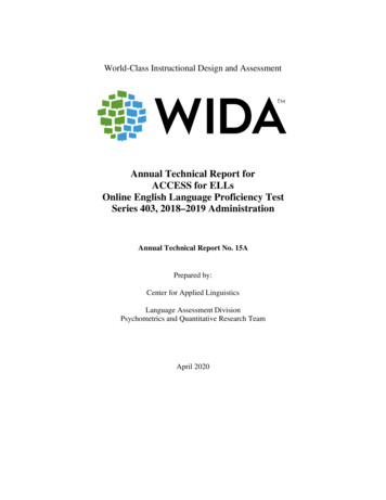
Proline Promass 80F, 83FMeasuring systemThe measuring system consists of a transmitter and a sensor. Two versions are available: Compact version: transmitter and sensor form a mechanical unit Remote version: transmitter and sensor are mounted physically separate from one anotherTransmitterPromass 80 Two-line liquid-crystal display Operation with push buttons-Esc Ea0003671 Promass 83Four-line liquid-crystal displayOperation with "Touch control"Application-specific Quick SetupMass flow, volume flow, density and temperature measurement as well ascalculated variables (e.g. fluid concentrations)Esc– Ea0003672SensorF Universal sensor for fluid temperaturesup to 200 C ( 392 F). Nominal diameters DN 8 to 250 (3/8" to 10"). Material: Stainless Steel EN 1.4539/ASTM 904L,EN 1.4404/ASTM 316L, Alloy C-22 DIN 2.4602Documentation No.TI101Da0003673F (High-temperature) Universal high-temperature sensor for fluid temperaturesup to 350 C ( 662 F). Nominal diameters DN 25, 50, 80 (1", 2", 3") Material: Alloy C-22, DIN 2.4602,EN 1.4404/ASTM 316La0003675Other sensors can be found in the separate documentationA Single-tube system for highly accurate measurement ofvery small flows Nominal diameters DN 1 to 4 (1/24" to 1/8") Material: Stainless Steel EN 1.4539/ASTM 904L,EN 1.4404/ASTM 316L , Alloy C-22 DIN 2.4602(process connection)Documentation No.TI054D General purpose sensor, ideal replacement for volumetricflowmeters. Nominal diameters DN DN 8 to 50 (3/8" to 2") Material: Stainless Steel EN 1.4539/ASTM 904L,EN 1.4404/ASTM 316LDocumentation No.TI061Da0003679Ea00022714Endress Hauser
Proline Promass 80F, 83FH Single bent tube. Low pressure loss and chemicallyresistant material Nominal diameters DN 8 to 50 (3/8" to 2") Material: Zirconium 702/R 60702, Tantalum 2.5WDocumentation No.TI074D Straight single-tube instrument. Minimal shear stress onfluid, hygienic design, low pressure loss Nominal diameters DN 8 to 80 (3/8" to 3") Material: Titanium, Ti Grade 2, Ti Grade 9Documentation No.TI075D Robust sensor for extreme process pressures, highrequirements for the secondary containment and fluidtemperatures up to 150 C ( 302 F) Nominal diameters DN 8 to 80 (3/8" to 3") Material: Titanium, Ti Grade 2, Ti Grade 9Documentation No.TI102D Single bent tube, minimal shear stress on fluid.Hygienic design with documents for Life ScienceIndustries applications, low pressure loss, for fluidtemperatures up to 200 C ( 392 F). Nominal diameters DN 8 to 50 (3/8" to 2") Material: Stainless Steel EN 1.4435/ASTM 316LDocumentation No.TI078D Single bent tube.Hygienic design, low pressure loss, for fluid temperaturesup to 150 C ( 302 F) Nominal diameters DN 8 to 50 (3/8" to 2") Material: Stainless Steel, EN 1.4539/ASTM 904L,EN 1.4435/ASTM 316LDocumentation 828Endress Hauser5
Proline Promass 80F, 83FInputMeasured variable Mass flow (proportional to the phase difference between two sensors mounted on the measuring tube toregister a phase shift in the oscillation) Fluid density (proportional to resonance frequency of the measuring tube) Fluid temperature (measured with temperature sensors)Measuring rangeMeasuring ranges for liquidsRange for full scale values (liquids) gmin(F) to gmax(F)DN[mm][inch][kg/h][lb/min]83/8"0 to 20000 to 73.515½"0 to 65000 to 238251"0 to 18 0000 to 660401½"0 to 45 0000 to 1650502"0 to 70 0000 to 2570803"0 to 1800000 to 66001004"0 to 3500000 to 128601506"0 to 8000000 to 2940025010"0 to 22000000 to 80840Measuring ranges for gasesThe full scale values depend on the density of the gas. Use the formula below to calculate the full scale values:gmax(G) gmax(F) · ρ(G) x [kg/m³ (lb/ft³)]gmax(G) max. full scale value for gas [kg/h (lb/min)]gmax(F) max. full scale value for liquid [kg/h (lb/min)]ρ(G) gas density in [kg/m³ (lb/ft³)] under process 90Here, gmax(G) can never be greater than gmax(F)Calculation example for gas: Sensor type: Promass F, DN 50Gas: air with a density of 60.3 kg/m³ (at 20 C and 50 bar)Measuring range (liquid): 70000 kg/hx 90 (for Promass F DN 50)Max. possible full scale value:gmax(G) gmax(F) · ρ(G) x [kg/m³] 70000 kg/h · 60.3 kg/m³ 90 kg/m³ 46900 kg/hRecommended measuring ranges:See information in the "Limiting flow" Section ä 236Endress Hauser
Proline Promass 80F, 83FOperable flow rangeGreater than 1000 :1. Flow rates above the preset full scale value do not overload the amplifier, i.e. the totalizervalues are registered correctly.Input signalStatus input (auxiliary input)U 3 to 30 V DC, Ri 5 kΩ, galvanically isolated.Configurable for: totalizer reset, positive zero return, error message reset, zero point adjustment start, batchingstart/stop (optional), totalizer reset for batching (optional).Status input (auxiliary input) with PROFIBUS DPU 3 to 30 V DC, Ri 3 kΩ, galvanically isolated.Switch level: 3 to 30 V DC, independent of polarity.Configurable for: positive zero return, error message reset, zero point adjustment start, batching start/stop(optional), totalizer reset for batching (optional).Status input (auxiliary input) with MODBUS RS485U 3 to 30 V DC, Ri 3 kΩ, galvanically isolated.Switch level: 3 to 30 V DC, independent of polarity.Configurable for: totalizer reset, positive zero return, error message reset, zero point adjustment start.Current input (only Promass 83)Active/passive selectable, galvanically isolated, resolution: 2 μA Active: 4 to 20 mA, RL 700 Ω, Uout 24 V DC, short-circuit proof Passive: 0/4 to 20 mA, Ri 150 Ω, Umax 30 V DCEndress Hauser7
Proline Promass 80F, 83FOutputOutput signalPromass 80Current outputActive/passive selectable, galvanically isolated, time constant selectable (0.05 to 100 s), full scale valueselectable, temperature coefficient: typically 0.005% o.f.s./ C, resolution: 0.5 μA Active: 0/4 to 20 mA, RL 700 Ω (for HART: RL 250 Ω) Passive: 4 to 20 mA; supply voltage US 18 to 30 V DC; Ri 150 ΩPulse/frequency outputPassive, open collector, 30 V DC, 250 mA, galvanically isolated. Frequency output: full scale frequency 2 to 1000 Hz (fmax 1250 Hz), on/off ratio 1:1, pulse width max. 2 s Pulse output: pulse value and pulse polarity selectable, pulse width configurable (0.5 to 2000 ms)PROFIBUS PA interface PROFIBUS PA in accordance with EN 50170 Volume 2, IEC 61158-2 (MBP), galvanically isolatedProfile Version 3.0Current consumption: 11 mAPermitted supply voltage: 9 to 32 VBus connection with integrated reverse polarity protectionError current FDE (Fault Disconnection Electronic) 0 mAData transmission rate: 31.25 kBit/sSignal encoding: Manchester IIFunction blocks: 4 Analog Input, 2 TotalizerOutput data: Mass flow, Volume flow, Density, Temperature, TotalizerInput data: Positive zero return (ON/OFF), Zero point adjustment, Measuring mode, Totalizer controlBus address can be configured via miniature switches or via the local display (optional)Promass 83Current outputActive/passive selectable, galvanically isolated, time constant selectable (0.05 to 100 s), full scale valueselectable, temperature coefficient: typically 0.005% o.f.s./ C, resolution: 0.5 μA Active: 0/4 to 20 mA, RL 700 Ω (for HART: RL 250 Ω) Passive: 4 to 20 mA; supply voltage US 18 to 30 V DC; Ri 150 ΩPulse/frequency outputactive/passive selectable, galvanically isolated Active: 24 V DC, 25 mA (max. 250 mA during 20 ms), RL 100 Ω Passive: open collector, 30 V DC, 250 mA Frequency output:full scale frequency 2 to 10000 Hz (fmax 12500 Hz), on/off ratio 1:1, pulse width max. 2 s Pulse output:pulse value and pulse polarity selectable, pulse width configurable (0.05 to 2000 ms)PROFIBUS DP interface PROFIBUS DP in accordance with EN 50170 Volume 2Profile Version 3.0Data transmission rate: 9.6 kBaud to 12 MBaudAutomatic data transmission rate recognitionSignal encoding: NRZ CodeFunction blocks: 6 Analog Input, 3 TotalizerOutput data: Mass flow, Volume flow, Corrected volume flow, Density, Reference density, Temperature,Totalizers 1 to 3 Input data: Positive zero return (ON/OFF), Zero point adjustment, Measuring mode, Totalizer control Bus address can be configured via miniature switches or via the local display (optional) Available output combination ä 128Endress Hauser
Proline Promass 80F, 83FPROFIBUS PA interface PROFIBUS PA in accordance with EN 50170 Volume 2, IEC 61158-2 (MBP), galvanically isolated Data transmission rate:31.25 kBit/s Current consumption: 11 mA Permitted supply voltage: 9 to 32 V Bus connection withintegrated reverse polarity protection Error current FDE (Fault Disconnection Electronic): 0 mA Signal encoding: Manchester II Function blocks: 6 Analog Input, 3 Totalizer Output data: Mass flow, Volume flow, Corrected volume flow, Density, Reference density, Temperature,Totalizers 1 to 3 Input data: Positive zero return (ON/OFF), Zero point adjustment, Measuring mode, Totalizer control Bus address can be configured via miniature switches or via the local display (optional) Available output combination ä 12MODBUS interface MODBUS device type: slaveAddress range: 1 to 247Supported function codes: 03, 04, 06, 08, 16, 23Broadcast: supported with the function codes 06, 16, 23Physical interface: RS485 in accordance with EIA/TIA-485 standardSupported baud rate: 1200, 2400, 4800, 9600, 19200, 38400, 57600, 115200 BaudTransmission mode: RTU or ASCIIResponse times:Direct data access typically 25 to 50 msAuto-scan buffer (data range) typically 3 to 5 ms Possible output combinations ä 12FOUNDATION Fieldbus interface Endress HauserFOUNDATION Fieldbus H1, IEC 61158-2, galvanically isolatedData transmission rate: 31.25 kBit/sCurrent consumption: 12 mAPermitted supply voltage: 9 to 32 VError current FDE (Fault Disconnection Electronic): 0 mABus connection with integrated reverse polarity protectionSignal encoding: Manchester IIITK Version 5.01Function blocks:– 8 Analog Input (Execution time: each 18 ms)– 1 Digital Output (18 ms)– 1 PID (25 ms)– 1 Arithmetic (20 ms)– 1 Input Selector (20 ms)– 1 Signal Characterizer (20 ms)– 1 Integrator (18 ms)Number of VCRs: 38Number of link objects in VFD: 40Output data: Mass flow, Volume flow, Corrected volume flow, Density, Reference density, Temperature,Totalizers 1 to 3Input data: Positive zero return (ON/OFF), Zero point adjustment, Measuring mode, Reset totalizerLink Master (LM) function is supported9
Proline Promass 80F, 83FSignal on alarmCurrent outputFailsafe mode selectable (e.g. in accordance with NAMUR Recommendation NE 43)Pulse/frequency outputFailsafe mode selectableStatus output (Promass 80)Nonconductive in the event of a fault or if the power supply failsRelay output (Promass 83)Dead in the event of a fault or if the power supply failsLoadsee "Output signal"Low flow cutoffSwitch points for low flow are selectable.Galvanic isolationAll circuits for inputs, outputs, and power supply are galvanically isolated from each other.Switching outputStatus output (Promass 80) Open collectormax. 30 V DC / 250 mAgalvanically isolatedConfigurable for: error messages, Empty Pipe Detection (EPD), flow direction, limit valuesRelay output (Promass 83) max. 30 V / 0.5 A AC; 60 V / 0.1 A DC galvanically isolated Normally closed (NC or break) or normally open (NO or make) contacts available(factory setting: relay 1 NO, relay 2 NC)10Endress Hauser
Proline Promass 80F, 83FPower supplyElectrical connectionMeasuring unitACBddgbgbaaab d/(g) (d)PROFIBUS PA*FOUNDATION Fieldbus*HART*f– 27 26– 25 24– 23 22– 21 20N (L-) 2L1 (L )1PA(–)/FF(–)PA( )/FF( )– f– – dec2726252423222120N (L-) 2L1 (L ) 1bN (L-) 2L1 (L ) 1ecbPROFIBUS DP**MODBUS RS485**PROFIBUS DP*A (RxD/TxD-N) 27B (RxD/TxD-P) 26– 25 24f– 23 22– 21 20ddegA (RxD/TxD-N)B (RxD/TxD-P)– f– – cb2726252423222120N (L-) 2L1 (L ) 1degcba0002441Connecting the transmitter, cable cross-section: max. 2.5 mm²ABCView A (field housing)View B (Stainless Steel field housing)View C (wall-mount housing)*)**)abfixed communication boardflexible communication boardConnection compartment coverCable for power supply: 85 to 260 V AC, 20 to 55 V AC, 16 to 62 V DCTerminal No. 1: L1 for AC, L for DCTerminal No. 2: N for AC, L- for DCGround terminal for protective groundSignal cable: see Terminal assignment ä 12Fieldbus cable:Terminal No. 26: DP (B) / PA ( ) / FF ( ) / MODBUS RS485 (B) / (PA, FF: with reverse polarity protection)Terminal No. 27: DP (A) / PA (–) / FF (–) / MODBUS RS485 (A) / (PA, FF: with reverse polarity protection)Ground terminal for signal cable shield / fieldbus cable / RS485 lineService adapter for connecting service interface FXA 193 (Fieldcheck, FieldCare)Signal cable: see Terminal assignment ä 12Cable for external termination (only for PROFIBUS DP with permanent assignment communication board):Terminal No. 24: 5 VTerminal No. 25: DGNDcdefggEndress Hauser11
Proline Promass 80F, 83FElectrical connection,terminal assignmentPromass 80Terminal No. (inputs/outputs)Order version20 ( ) / 21 (–)22 ( ) / 23 (–)24 ( ) / 25 (–)26 ( ) / 27 (–)80***-***********A--Frequency outputCurrent output, HART80***-***********DStatus inputStatus outputFrequency outputCurrent output, HART80***-***********H---PROFIBUS PA80***-***********S--Frequency outputEx i, passiveCurrent output Ex iActive, HART80***-***********T--Frequency outputEx i, passiveCurrent output Ex iPassive, HART80***-***********8Status inputFrequency outputCurrent output 2Current output 1,HARTPromass 83The inputs and outputs on the communication board can be either permanently assigned (fixed) or variable(flexible), depending on the version ordered (see table). Replacements for modules which are defective orwhich have to be replaced can be ordered as accessories.Terminal No. (inputs/outputs)Order version20 ( ) / 21 (–)22 ( ) / 23 (–)24 ( ) / 25 (–)26 ( ) / 27 (–)Fixed communication boards (permanent assignment)83***-***********A--Frequency outputCurrent output, HART83***-***********BRelay outputRelay outputFrequency outputCurrent output, HART83***-***********F---PROFIBUS PA, Ex i83***-***********G---FOUNDATIONFieldbus Ex i83***-***********H---PROFIBUS PA83***-***********J-- 5V(ext. termination)PROFIBUS **********Q--Status inputMODBUS RS48583***-***********R--Current output 2Ex i, activeCurrent output 1Ex i active, HART83***-***********S--Frequency outputEx i, passiveCurrent output Ex iActive, HART83***-***********T--Frequency outputEx i, passiveCurrent output Ex iPassive, HART83***-***********U--Current output 2Ex i, passiveCurrent output 1Ex i passive, HARTFlexible communication boards1283***-***********CRelay output 2Relay output 1Frequency outputCurrent output, HART83***-***********DStatus inputRelay outputFrequency outputCurrent output, HART83***-***********EStatus inputRelay outputCurrent output 2Current output, HART83***-***********LStatus inputRelay output 2Relay output 1Current output, HART83***-***********MStatus inputFrequency output 2 Frequency output 1Current output, HART83***–***********NCurrent outputFrequency outputStatus inputMODBUS RS48583***–***********PCurrent outputFrequency outputStatus inputPROFIBUS DPEndress Hauser
Proline Promass 80F, 83FTerminal No. (inputs/outputs)Order version20 ( ) / 21 (–)22 ( ) / 23 (–)24 ( ) / 25 (–)26 ( ) / 27 (–)83***–***********VRelay output 2Relay output 1Status inputPROFIBUS DP83***-***********WRelay outputCurrent output 3Current output 2Current output 1, HART83***-***********0Status inputCurrent output 3Current output 2Current output 1, HART83***-***********2Relay outputCurrent output 2Frequency outputCurrent output 1, HART83***-***********3Current inputRelay outputCurrent output 2Current output 1, HART83***-***********4Current inputRelay outputFrequency outputCurrent output, HART83***-***********5Status inputCurrent inputFrequency outputCurrent output, HART83***-***********6Status inputCurrent inputCurrent output 2Current output 1, HART83***–***********7Relay output 2Relay output 1Status inputMODBUS RS485Electrical connectionRemote versionaS1 S1 S2 S2 GND TM TM TT TT b4567891011 1241 424 5 6 7 8 9 10 11 12 S1 S1 S2 S2 GND TM TM TT TT41 42dddeca0003681Connecting the remote versionabcdeWall-mount housing: non-hazardous area and ATEX II3G / zone 2 see separate "Ex documentation"Wall-mount housing: ATEX II2G / Zone 1 /FM/CSA see separate "Ex documentation"Remote version, flanged versionCover for connection compartment or connection housingConnecting cableTerminal No.: 4/5 gray; 6/7 green; 8 yellow; 9/10 pink; 11/12 white; 41/42 brownSupply voltage85 to 260 V AC, 45 to 65 Hz20 to 55 V AC, 45 to 65 Hz16 to 62 V DCCable entriesPower-supply and signal cables (inputs/outputs): Cable entry M20 1.5 (8 to 12 mm) (0.31" to 0.47") Thread for cable entries, ½" NPT, G ½"Connecting cable for remote version: Cable entry M20 1.5 (8 to 12 mm) (0.31" to 0.47") Thread for cable entries, ½" NPT, G ½"Endress Hauser13
Proline Promass 80F, 83FRemote version cablespecification 6 0.38 mm² (PVC cable with common shield and individually shielded coresConductor resistance: 50 Ω/kmCapacitance: core/shield: 420 pF/mCable length: max. 20 m (65 ft)Permanent operating temperature: max. 105 C ( 221 F)Operation in zones of severe electrical interference:The measuring device complies with the general safety requirements in accordance with EN 61010, the EMCrequirements of EN 61326/A1, and NAMUR recommendation NE 21/43.Power consumptionAC: 15 VA (including sensor)DC: 15 W (including sensor)Switch-on current: Max. 13.5 A ( 50 ms) at 24 V DC Max. 3 A ( 5 ms) at 260 V ACPower supply failurePromass 80Lasting min. 1 power cycle: EEPROM saves measuring system data if the power supply fails HistoROM/S-DAT: exchangeable data storage chip with sensor specific data (nominal diameter, serialnumber, calibration factor, zero point, etc.)Promass 83Lasting min. 1 power cycle: EEPROM and T-DAT save the measuring system data if the power supply fails. HistoROM/S-DAT: exchangeable data storage chip with sensor specific data (nominal diameter, serialnumber, calibration factor, zero point, etc.)Potential equalization14No special measures for potential equalization are required. For instruments for use in hazardous areas, observethe corresponding guidelines in the specific Ex documentation.Endress Hauser
Proline Promass 80F, 83FPerformance characteristicsReference operatingconditions Error limits following ISO/DIS 11631Water, typically 20 to 30 C ( 68 to 86 F); 2 to 4 bar (30 to 60 psi)Data according to calibration protocol 5 C ( 9 F) and 2 bar ( 30 psi)Accuracy based on accredited calibration rigs according to ISO 17025Maximum measured errorThe following values refer to the pulse/frequency output. The additional measured error at the current outputis typically 5 μA. Design fundamentals ä 17.o.r. of readingMasse flow and volume flow (liquid)Promass 83F: 0.05% o.r. (PremiumCal, for mass flow) 0.10% o.rPromass 80F: 0.10% o.r. (optional) 0.15% o.r.Mass flow (gas)Promass 83F, 80F: 0.35% o.r.Density (liquid) 0.0005 g/cc (under reference conditions) 0.0005 g/cc (after field density calibration under process conditions) 0.001 g/cc (after special density calibration) 0.01 g/cc (over the entire measuring range of the sensor)1 g/cc 1 kg/lSpecial density calibration (opti
Mass flow, volume flow, density and temperature measurement as well as calculated variables (e.g. fluid concentrations) F a0003673 Universal sensor for fluid temperatures up to 200 C ( 392 F). Nominal diameters DN 8 to 250 (3/8" to 10"). Material: Stainless Steel EN 1.4539/ASTM 904L, EN 1.4404/ASTM 316L, Alloy C-22 DIN 2.4602