Transcription
Technical InformationProline Promass F 100Coriolis Mass Flow Measuring SystemUnsurpassed accuracy and robustness combined with seamlesssystem integrationApplicationYour benefits Highest measurement accuracy for liquids and gasesunder varying process conditions. The Coriolis measuring principle operatesindependently of physical fluid properties, such asviscosity and density.Sensor for unsurpassed accuracy and robustness indemanding applications combined with an ultra compacttransmitterDevice properties Mass flow: PremiumCal 0.05 % Immunity to varying process pressure and mediumtemperature Secondary containment: Max. 40 bar (580 psi) Ultra compact transmitter made of aluminum orstainless steel (316L) Communication via 4-20 mA HART, Pulse/frequency/switch, EtherNet/IP and Modbus RS485 Ex approvals accepted worldwide:ATEX, IECEx, cCSAus, NEPSISizing - correct product selectionApplicator - the reliable, easy-to-use tool for selecting andsizing measuring devices for every applicationInstallation - simple and efficient Immune to external piping forces and vibration No inlet/outlet runs required Reduced effort for wiring thanks to device plugsCommissioning - reliable and intuitiveIntegrated web server for fast commissioningOperation - increased measurement availability Multivariable measurement: flow and density Immune to process influences Diagnostics; Automatic data restore by HistoROMCost-effective Life Cycle Management by W@MTI01034D/06/EN/01.1271165098
Table of contentsProline Promass F 100Table of contentsDocument information . . . . . . . . . . . . . . . . . . . . . . . . 3Symbols used . . . . . . . . . . . . . . . . . . . . . . . . . . . . . . . . . 3Function and system design . . . . . . . . . . . . . . . . . . . . 4Measuring principle . . . . . . . . . . . . . . . . . . . . . . . . . . . . . 4Measuring system . . . . . . . . . . . . . . . . . . . . . . . . . . . . . . 5Device architecture . . . . . . . . . . . . . . . . . . . . . . . . . . . . . 6Input . . . . . . . . . . . . . . . . . . . . . . . . . . . . . . . . . . . . . 6Measured variable . . . . . . . . . . . . . . . . . . . . .Measuring range . . . . . . . . . . . . . . . . . . . . . .Operable flow range . . . . . . . . . . . . . . . . . . . .Input signal . . . . . . . . . . . . . . . . . . . . . . . . .6677Output . . . . . . . . . . . . . . . . . . . . . . . . . . . . . . . . . . . . 8Output signal . . . . . . . . . . . . . . . . . . . . . . .Signal on alarm . . . . . . . . . . . . . . . . . . . . . .Ex connection data . . . . . . . . . . . . . . . . . . .Low flow cut off . . . . . . . . . . . . . . . . . . . . .Galvanic isolation . . . . . . . . . . . . . . . . . . . .Protocol-specific data . . . . . . . . . . . . . . . . . . 8. 9. . . . . . . . 10. . . . . . . . 11. . . . . . . . 11. . . . . . . . 11Power supply . . . . . . . . . . . . . . . . . . . . . . . . . . . . . 15Terminal assignment . . . . . . . . . . . . . . . . . . . . . . . .Pin assignment, device plug . . . . . . . . . . . . . . . . . . . .Supply voltage . . . . . . . . . . . . . . . . . . . . . . . . . . . .Power consumption . . . . . . . . . . . . . . . . . . . . . . . . .Current consumption . . . . . . . . . . . . . . . . . . . . . . . .Power supply failure . . . . . . . . . . . . . . . . . . . . . . . . .Electrical connection . . . . . . . . . . . . . . . . . . . . . . . .Potential equalization . . . . . . . . . . . . . . . . . . . . . . . .Terminals . . . . . . . . . . . . . . . . . . . . . . . . . . . . . . .Cable entries . . . . . . . . . . . . . . . . . . . . . . . . . . . . .Cable specification . . . . . . . . . . . . . . . . . . . . . . . . . .1518191920202023232323Performance characteristics . . . . . . . . . . . . . . . . . . . 24Reference operating conditions . . . . . . . . . . . . . . . . . .Maximum measured error . . . . . . . . . . . . . . . . . . . . .Repeatability . . . . . . . . . . . . . . . . . . . . . . . . . . . . .Response time . . . . . . . . . . . . . . . . . . . . . . . . . . . .Influence of ambient temperature . . . . . . . . . . . . . . . .Influence of medium temperature . . . . . . . . . . . . . . . .Influence of medium pressure . . . . . . . . . . . . . . . . . . .Design fundamentals . . . . . . . . . . . . . . . . . . . . . . . .2424262627272728Installation . . . . . . . . . . . . . . . . . . . . . . . . . . . . . . . 28Mounting location . . . . . . . . . . . . . . . . . . . . . . . . . . .Orientation . . . . . . . . . . . . . . . . . . . . . . . . . . . . . . .Inlet and outlet runs . . . . . . . . . . . . . . . . . . . . . . . . . .Special mounting instructions . . . . . . . . . . . . . . . . . . . .Mounting Safety Barrier Promass100 . . . . . . . . . . . . . . .2829303032Degree of protection . . . . . . . . . . . . . . . . . . . . . . . . . .Shock resistance . . . . . . . . . . . . . . . . . . . . . . . . . . . .Vibration resistance . . . . . . . . . . . . . . . . . . . . . . . . . .Interior cleaning . . . . . . . . . . . . . . . . . . . . . . . . . . . .Electromagnetic compatibility (EMC) . . . . . . . . . . . . . . .3434343434Process . . . . . . . . . . . . . . . . . . . . . . . . . . . . . . . . . . 34Medium temperature range . . . . . . . . . . . . . . . . . . . . .Medium density . . . . . . . . . . . . . . . . . . . . . . . . . . . .Pressure-temperature ratings . . . . . . . . . . . . . . . . . . . .Secondary containment pressure range . . . . . . . . . . . . . .Rupture disk . . . . . . . . . . . . . . . . . . . . . . . . . . . . . .Flow limit . . . . . . . . . . . . . . . . . . . . . . . . . . . . . . . .Pressure loss . . . . . . . . . . . . . . . . . . . . . . . . . . . . . .System pressure . . . . . . . . . . . . . . . . . . . . . . . . . . . .Heating . . . . . . . . . . . . . . . . . . . . . . . . . . . . . . . . . .Vibrations . . . . . . . . . . . . . . . . . . . . . . . . . . . . . . . .34343439393939393939Mechanical construction . . . . . . . . . . . . . . . . . . . . . 40Design, dimensions . . . . . . . . . . . . . . . . . . . . . . . .Weight . . . . . . . . . . . . . . . . . . . . . . . . . . . . . . . .Materials . . . . . . . . . . . . . . . . . . . . . . . . . . . . . . .Process connections . . . . . . . . . . . . . . . . . . . . . . . .40596061Operability . . . . . . . . . . . . . . . . . . . . . . . . . . . . . . . 61Operating concept . . . . . . . . . . . . . . . . . . . . . . . . . . . . . 61Remote operation . . . . . . . . . . . . . . . . . . . . . . . . . . . . . 62Certificates and approvals . . . . . . . . . . . . . . . . . . . . 64CE mark . . . . . . . . . . . . . . . . . . . . . . . . . . . . . . .C-Tick symbol . . . . . . . . . . . . . . . . . . . . . . . . . . .Ex approval . . . . . . . . . . . . . . . . . . . . . . . . . . . . .Hygienic compatibility . . . . . . . . . . . . . . . . . . . . . .Pressure Equipment Directive . . . . . . . . . . . . . . . . . .Other standards and guidelines . . . . . . . . . . . . . . . . .646464656565Ordering information . . . . . . . . . . . . . . . . . . . . . . . . 66Accessories . . . . . . . . . . . . . . . . . . . . . . . . . . . . . . . 66Device-specific accessories . . . . . . . . . . . . . . . . . . . .Communication-specific accessories . . . . . . . . . . . . . .Service-specific accessories . . . . . . . . . . . . . . . . . . . .System components . . . . . . . . . . . . . . . . . . . . . . . .66666767Documentation . . . . . . . . . . . . . . . . . . . . . . . . . . . . 68Standard documentation . . . . . . . . . . . . . . . . . . . . . . . . . 68Supplementary device-dependent documentation . . . . . . . . . . 68Registered trademarks . . . . . . . . . . . . . . . . . . . . . . . 68Environment . . . . . . . . . . . . . . . . . . . . . . . . . . . . . . 32Ambient temperature range . . . . . . . . . . . . . . . . . . . . . . . 32Storage temperature . . . . . . . . . . . . . . . . . . . . . . . . . . . . 33Climate class . . . . . . . . . . . . . . . . . . . . . . . . . . . . . . . . 332Endress Hauser
Proline Promass F 100Document informationSymbols usedElectrical symbolsSymbolMeaningDirect currentA terminal to which DC voltage is applied or through which direct current flows.A0011197Alternating currentA terminal to which alternating voltage is applied or through which alternating current flows.A0011198Direct current and alternating current A terminal to which alternating voltage or DC voltage is applied. A terminal through which alternating current or direct current flows.A0017381)Ground connectionA grounded terminal which, as far as the operator is concerned, is grounded via a grounding system.*Protective ground connectionA terminal which must be connected to ground prior to establishing any other connections.A0011200A0011199Equipotential connectionA connection that has to be connected to the plant grounding system: This may be a potential equalizationline or a star grounding system depending on national or company codes of practice.A0011201Symbols for certain types of informationMeaningSymbolAllowedIndicates procedures, processes or actions that are allowed.A0011182PreferredIndicates procedures, processes or actions that are preferred.A0011183ForbiddenIndicates procedures, processes or actions that are forbidden.A0011184TipIndicates additional information.A0011193Reference to documentationRefers to the corresponding device documentation.A0011194Reference to pageRefers to the corresponding page number.A0011195Reference to graphicRefers to the corresponding graphic number and page number.A0011196Symbols in graphicsSymbolMeaning1, 2, 3,.,, A, B, C, .A-A, B-B, C-C, .Item numbersSeries of stepsViewsSectionsFlow directionA0013441Endress Hauser3
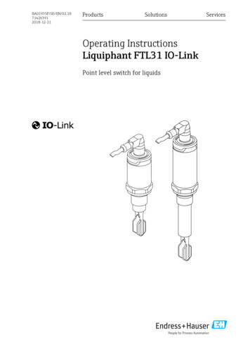
Proline Promass F 100Symbol-MeaningA0011187Hazardous areaIndicates a hazardous area.Safe area (non-hazardous area)Indicates a non-hazardous area.A0011188Function and system designMeasuring principleThe measuring principle is based on the controlled generation of Coriolis forces. These forces are always presentin a system when both translational and rotational movements are superimposed.Fc 2 Dm (n w)Fc Coriolis forceDm moving massw Rotational velocityn radial velocity in rotating or oscillating systemThe amplitude of the Coriolis force depends on the moving mass Dm, its velocity n in the system and thus onthe mass flow. Instead of a constant rotational velocity, the Promass sensor uses oscillation w.In the sensor, two parallel measuring tubes containing flowing fluid oscillate in antiphase, acting like a tuningfork. The Coriolis forces produced at the measuring tubes cause a phase shift in the tube oscillations (seeillustration): At zero flow (when the fluid is at a standstill) the two tubes oscillate in phase (1). Mass flow causes deceleration of the oscillation at the inlet of the tubes (2) and acceleration at the outlet (3).123A0016771The phase difference (A-B) increases with increasing mass flow. Electrodynamic sensors register the tubeoscillations at the inlet and outlet. System balance is ensured by the antiphase oscillation of the two measuringtubes. The measuring principle operates independently of temperature, pressure, viscosity, conductivity andflow profile.Density measurementThe measuring tube is continuously excited at its resonance frequency. A change in the mass and thus thedensity of the oscillating system (comprising measuring tube and fluid) results in a corresponding, automaticadjustment in the oscillation frequency. Resonance frequency is thus a function of fluid density. Themicroprocessor utilizes this relationship to obtain a density signal.Volume measurementTogether with the measured mass flow, this is used to calculate the volume flow.Temperature measurementThe temperature of the measuring tube is determined in order to calculate the compensation factor due totemperature effects. This signal corresponds to the process temperature and is also available as an output signal.4Endress Hauser
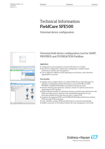
Proline Promass F 100Measuring systemThe device consists of a transmitter and a sensor. If a device with Modbus RS485 intrinsically safe is ordered,the Safety Barrier Promass 100 is part of the scope of supply and must be implemented to operate the device.One device version is available: compact version, transmitter and sensor form a mechanical unit.TransmitterPromass 100A0016693A0016694Device versions and materials: Compact:– Aluminum coating AlSi10Mg– Hygienic version, stainless steel 1.4301/304– Hygienic version, stainless steel 1.4404/316L Ultra-compact:– Hygienic version, stainless steel 1.4301/304– Hygienic version, stainless steel 1.4404/316LConfiguration: Via operating tools (e.g. FieldCare) Also for device version with 4-20 mA HART, pulse/frequency/switch output:Via Web browser (e.g. Microsoft Internet Explorer) Also for device version with EtherNet/IP output:– Via Web browser (e.g. Microsoft Internet Explorer)– Via Add-on Profile Level 3 for automation system from RockwellAutomation– Via Electronic Data Sheet (EDS)A0016695SensorPromass FA0016507 Excellent performance across a wide range of applications Simultaneous measurement of flow, volume flow, density and temperature(multivariable) Immune to process influences Nominal diameters: DN 8 to 250 (3/8 to 10") Materials:– Sensor: Stainless steel 1.4301/304; optional 1.4404/316L– Measuring tubes: Stainless steel 1.4539/904L; 1.4404/316L; Alloy C-222.4602/N 06022– Stainless steel 1.4404/316L; Alloy C-22 2.4602/N 06022Safety Barrier Promass 100A0016763Endress Hauser Dual-channel safety barrier for installation in non-hazardous locations or zone2/div. 2:– Channel 1: DC 24 V power supply– Channel 2: Modbus RS485 In addition to current, voltage and power limitation, it offers galvanic isolationof circuits for explosion protection. Easy top-hat rail mounting (DIN 35mm) for installation in control cabinets5
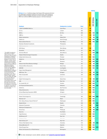
Proline Promass F 100Device ties for integrating measuring devices into a systemControl system (e.g. PLC)EtherNet/IPModbus RS4854-20 mA HART, pulse/frequency/switch outputSafety Barrier Promass 100Modbus RS485 intrinsically safeNon-hazardous areaNon-hazardous area and zone 2/div. 2Intrinsically safe areaInputMeasured variableDirect measured variables Mass flow Density TemperatureCalculated measured variables Volume flow Corrected volume flow Reference densityMeasuring rangeMeasuring ranges for liquidsDN6Measuring range full scale values gmin(F) to gmax(F)[mm][in][kg/h][lb/min]83/80 to 2 0000 to 73.515½0 to 6 5000 to 2382510 to 18 0000 to 660401½0 to 45 0000 to 1 6505020 to 70 0000 to 2 5708030 to 180 0000 to 6 60010040 to 350 0000 to 12 860Endress Hauser
Proline Promass F 100DNMeasuring range full scale values gmin(F) to gmax(F)[mm][in][kg/h][lb/min]15060 to 800 0000 to 29 400250100 to 2 200 0000 to 80 840Measuring ranges for gasesThe full scale values depend on the density of the gas and can be calculated with the formula below:gmax(G) g max(F) rG : xg max(G)Maximum full scale value for gas [kg/h]g max(F)Maximum full scale value for liquid [kg/h]g max(G) g max(F)g max(G) can never be greater than g max(F)rGGas density in [kg/m3] at operating 90502908031101004130150620025010200To calculate the measuring range, use the Applicator sizing tool ( ä 67)Calculation example for gas Sensor: Promass F, DN 50 Gas: Air with a density of 60.3 kg/m3 (at 20 C and 50 bar) Measuring range (liquid): 70 000 kg/h x 90 kg/m3 (for Promass F, DN 50)Maximum possible full scale value:g max(G) g max(F) rG : x 70 000 kg/h 60.3 kg/m3 : 90 kg/m3 46 900 kg/hRecommended measuring range"Flow limit" section ( ä 39)Operable flow rangeOver 1000 : 1. Flow rates above the preset full scale value are not overridden by the electronics unit, with theresult that the totalizer values are registered correctly.Input signalFieldbusesTo increase the accuracy of certain measured variables or to calculate the corrected volume flow for gases, theautomation system can continuously write different measured values to the measuring device via ModbusRS485 or EtherNet/IP: Process pressure or fluid temperature to increase accuracy (e.g. external values from Cerabar M, Cerabar Sor iTEMP) Reference density for calculating the corrected volume flowEndress Hauser7
Proline Promass F 100 Various pressure transmitters and temperature measuring devices can be ordered from Endress Hauser:see "Accessories" section ( ä 67) Please comply with the special mounting instructions if using pressure transmitters and temperaturemeasuring devices ( ä 30)OutputOutput signalCurrent outputCurrent output4-20 mA HART (active)Maximum output values DC 24 V (when idle) 22.5 mALoad0 to 700 ΩResolution0.38 µADampingAdjustable: 0 to 999 sAssignable measuredvariables Mass flowVolume flowCorrected volume flowDensityReference densityTemperaturePulse/frequency/switch outputFunctionCan be set to pulse, frequency or switch outputVersionPassive, open collectorMaximum input values DC 30 V 25 mAVoltage dropFor 25 mA: DC 2 VPulse outputPulse widthAdjustable:0.05 to 2 000 msMaximum pulse rate10 000 Impulse/sPulse valueAdjustableAssignable measuredvariables Mass flow Volume flow Corrected volume flowFrequency outputOutput frequencyAdjustable: 0 to 10 000 HzDampingAdjustable: 0 to 999 sPulse/pause ratio1:1Assignable measuredvariables Mass flowVolume flowCorrected volume flowDensityReference densityTemperatureSwitch output8Switching behaviorBinary, conductive or non-conductiveSwitching delayAdjustable: 0 to 100 sEndress Hauser
Proline Promass F 100Number of switching cycles UnlimitedAssignable functions OffOnDiagnostic behaviorLimit valueFlow direction monitoringStatus– Partial filled pipe detection– Low flow cut offModbus RS485Physical interfaceIn accordance with EIA/TIA-485-A standardTerminating resistor For device version used in non-hazardous areas or Zone 2/Div. 2: integrated and canbe activated via DIP switches on the transmitter electronics module For device version used in intrinsically safe areas: integrated and can be activated viaDIP switches on the Safety Barrier Promass 100EtherNet/IPStandardsSignal on alarmIn accordance with IEEE 802.3Depending on the interface, failure information is displayed as follows:Current output4-20 mAFailure modeSelectable (as per NAMUR recommendation NE 43): Minimum alarm: 3.6 mA Maximum alarm: 22 mA Adjustable value: 3.59 to 22.5 mAHARTDevice diagnosticsDevice condition can be read out via HART Command 48Pulse/frequency/switch outputPulse outputFailure modeChoose from: Actual value No pulsesFrequency outputFailure modeChoose from: Actual value Defined value: 0 to 12 500 Hz 0 HzSwitch outputFailure modeEndress HauserChoose from: Current status Open Closed9
Proline Promass F 100Modbus RS485Failure modeChoose from: NaN value instead of current value Last valid valueEtherNet/IPDevice diagnosticsDevice condition can be read out in Input AssemblyOperating tool Via digital communication: HART protocol Via service interfacePlain text displayWith information on cause and remedial measuresAdditional information on remote operation ( ä 62)Web browserPlain text displayWith information on cause and remedial measuresLight emitting diodes (LED)Status informationStatus indicated by various light emitting diodesThe following information is displayed depending on the device version: Supply voltage active Data transmission active Device alarm/error has occurred EtherNet/IP network available EtherNet/IP connection establishedEx connection dataThese values only apply for the following device version:Order code for "Output", option M: Modbus RS485, for use in intrinsically safe areasSafety Barrier Promass 100Safety-related valuesTerminal numbersSupply voltage2 (L-)Signal transmission1 (L )26 (A)Unom DC 24 VUmax AC 260 V27 (B)Unom DC 5 VUmax AC 260 VIntrinsically safe valuesTerminal numbersSupply voltage20 (L-)10Signal transmission10 (L )62 (A)72 (B)Endress Hauser
Proline Promass F 100Uo 16.24 VIo 623 mAPo 2.45 WFor IIC*: Lo 92.8 µH, Co 0.433 mF, Lo/Ro 14.6 mH/WFor IIB*: Lo 372 µH, Co 2.57 mF, Lo/Ro 58.3 mH/W*The gas group depends on the sensor and nominal diameter.For an overview and for information on the interdependencies between the gas group - sensor - nominal diameter,see the "Safety Instructions" (XA) document for the measuring deviceTransmitterIntrinsically safe valuesOrder code for"Approvals"Terminal numbersSupply voltage20 (L-) *Option BM: ATEX II2G IECEx Z1 Ex ia, II2D Ex tbOption BO: ATEX II1/2G IECEx Z0/Z1 Ex ia, II2DOption BQ: ATEX II1/2G IECEx Z0/Z1 Ex iaOption BU: ATEX II2G IECEx Z1 Ex iaOption C2: CSA C/US IS Cl. I, II, III Div. 1Option 85: ATEX II2G IECEx Z1 Ex ia CSA C/US ISCl. I, II, III Div. 1Signal transmission10 (L )62 (A)72 (B)Ui 16.24 VIi 623 mAPi 2.45 WLi 0 µHCi 6 nFThe gas group depends on the sensor and nominal diameter.For an overview and for information on the interdependencies between the gas group - sensor - nominal diameter,see the "Safety Instructions" (XA) document for the measuring deviceLow flow cut offThe switch points for low flow cut off are user-selectable.Galvanic isolationThe following connections are galvanically isolated from each other: Outputs Voltage supplyProtocol-specific dataHARTEndress HauserManufacturer ID0x11Device type ID0x4AHART protocol revision6.0Device description files (DTM,DD)Information and files under:www.endress.com11
Proline Promass F 100HART loadMin. 250 ΩDynamic variablesThe measured variables can be freely assigned to the dynamic variables.Measured variables for PV (primary dynamic variable) Mass flow Volume flow Corrected volume flow Density Reference density TemperatureMeasured variables for SV, TV, QV (secondary, tertiary and quaternarydynamic variable) Mass flow Volume flow Corrected volume flow Density Reference density Temperature Totalizer 1 Totalizer 2 Totalizer 3Modbus RS485ProtocolModbus Applications Protocol Specification V1.1Device typeSlaveSlave address range1 to 247Broadcast address range0Function codes Broadcast messagesSupported by the following function codes: 06: Write single registers 16: Write multiple registers 23: Read/write multiple registersSupported baud rate Data transmission mode ASCII RTUData accessEach device parameter can be accessed via Modbus RS485.03: Read holding register04: Read input register06: Write single registers08: Diagnostics16: Write multiple registers23: Read/write multiple registers1 200 BAUD2 400 BAUD4 800 BAUD9 600 BAUD19 200 BAUD38 400 BAUD57 600 BAUD115 200 BAUDFor Modbus register information ( ä 68)EtherNet/IP12Protocol The CIP Networks Library Volume 1: Common Industrial Protocol The CIP Networks Library Volume 2: EtherNet/IP Adaptation of CIPCommunication type 10Base-T 100Base-TXEndress Hauser
Proline Promass F 100Device profileGeneric device (product type: 0x43)Baud ratesAutomatic 10/100 Mbit with half-duplex and full-duplex detectionPolarityAuto-polarity for automatic correction of crossed TxD and RxD pairsSupported CIP connectionsMax. 3 connectionsExplicit connectionsMax. 5 connectionsI/O connectionsMax. 4 connections (scanner)Configuration options formeasuring device DIP switches on the electronics module for IP addressingManufacturer-specific software (FieldCare)Add-on Profile Level 3 for Rockwell Automation control systemsWeb browserElectronic Data Sheet (EDS) embedded in the measuring deviceConfiguration of MAC parameters Speed: Auto Duplex: AutoConfiguration of the deviceaddress DIP switches on the electronics module for IP addressing (last octet)DHCPManufacturer-specific software (FieldCare)Add-on Profile Level 3 for Rockwell Automation control systemsWeb browserEtherNet/IP tools, e.g. RSLinx (Rockwell Automation)Device Level Ring (DLR)NoFix InputExclusive Owner MulticastInstanceSize[Byte]RPI[ms]Instance configuration:0x68398-O T configuration:0x66645T O ance configuration:0x68398-O T configuration:0x670-T O ance configuration:0x68398-O T configuration:0x66645T O configuration:0x65885Input only MulticastInput Assembly Current device diagnosticsMass flowVolume flowCorrected volume flowDensityReference densityTemperatureTotalizer 1Totalizer 2Totalizer 3Configurable InputExclusive Owner MulticastEndress Hauser13
Proline Promass F 100Fix OutputOutput Assembly Activation of reset totalizers 1-3Activation of pressure compensationActivation of reference density compensationActivation of temperature compensationReset totalizers 1-3External pressure valuePressure unitExternal reference densityReference density unitExternal temperatureTemperature unitConfigurationConfiguration Assembly14 Software write protectionMass flow unitMass unitVolume flow unitVolume unitCorrected volume flow unitCorrected volume unitDensity unitReference density unitTemperature unitPressure unitLengthTotalizer 1-3:– Assignment– Unit– Operating mode– Failure mode Alarm delayEndress Hauser
Proline Promass F 100Power supplyTerminal assignmentOverview: housing version - signal transmission - terminals/connectors1321.1 1.2 1.3A2.1 ing version: compact, aluminum coatedHousing version: compact hygienic, stainlessHousing version: ultra-compact hygienic, stainless, connector M12Connection version: 4-20 mA HART, pulse/frequency/switch outputSignal transmission: Pulse/frequency/switch outputSignal transmission: 4-20 mA HARTSupply voltageConnection version: Modbus RS485Signal transmissionSupply voltageConnection version: EtherNet/IPSignal transmissionSupply voltageDepending on the housing version, the transmitters can be ordered with terminals or connectors.Endress Hauser15
Proline Promass F 100 Order code for "Housing", option A: compact, aluminum coated Order code for "Housing", option B: compact hygienic, stainlessOrder code for"Output"Connection methodFor supplyvoltageOrder code for"Electrical connection"For output Option B: 4-20 mA HART, pulse/Terminals( äfrequency/switch output17) Option M: Modbus RS485, for use inintrinsically safe areas Option M: Modbus RS485, for use innon-hazardous areas and Zone 2/Div. 2Terminals( ä17) Option B: 4-20 mA HART, pulse/Terminals( äfrequency/switch output17) Option M: Modbus RS485, for use innon-hazardous areas and Zone 2/Div. 2 Option N: EtherNet/IPConnector( ä 18) Option L: connector M12 threadNPT ½" Option N: connector M12x1 coupling M20 Option P: connector M12x1 thread G ½" Option U: connector M12x1 thread M20 Option B: 4-20 mA HART, pulse/Connectorfrequency/switch output( ä 18) Option M: Modbus RS485, for use innon-hazardous areas and Zone 2/Div. 2 Option N: EtherNet/IPConnector( ä 18)Option Q: 2 x connector M12x1Option M: Modbus RS485, for use inintrinsically safe areasConnector ( ä 18)Option A: coupling M20x1Option B: thread M20x1Option C: thread G ½"Option D: thread NPT ½"Option I: connector M12x1Order code for "Housing", option C: ultra-compact hygienic, stainless, connector M12Order code for"Output"Connection methodFor supplyvoltage Option B: 4-20 mA HART, pulse/Connectorfrequency/switch output( ä 18) Option M: Modbus RS485, for use innon-hazardous areas and Zone 2/Div. 2 Option N: EtherNet/IPOption M: Modbus RS485, for use inintrinsically safe areas16For outputConnector( ä 18)Connector ( ä 18)Order code for"Electrical connection"Option Q: 2 x connector M12x1Option I: connector M12x1Endress Hauser
Proline Promass F 100TransmitterConnection version 4-20 mA HART with pulse/frequency/switch output2425 32627 21 L 2 L1A0016888123Order code for "Power supply", option D: DC 24 VOrder code for "Output", option B: 4-20 mA HART (active, output 1)Order code for "Output", option B: pulse/frequency/switch output (passive, output 2)Modbus RS485 connection version12627AB1 L 2 L21.262721.110 L 20 LAB2.22.1A001705311.11.222.12.2Connection version for use in non-hazardous areas and Zone 2/Div. 2Order code for "Power supply", option D: DC 24 VOrder code for "Output", option M: Modbus RS485Connection version for use in intrinsically safe areas (connection via Safety Barrier Promass 100)Order code for "Power supply", option D: DC 24 VOrder code for "Output", option M: Modbus RS485EtherNet/IP connection version21 L 2 L1A001705412Endress HauserOrder code for "Power supply", option D: DC 24 VOrder code for "Output", option N: EtherNet/IP17
Proline Promass F 100Safety Barrier Promass 1002 1L L 26 27A BPowersupply24VDCModbusRS4851Safe areaPowerLift panel forbus terminationCommunicationASafety BarrierPromass 100Hazardous areaAPowersupplyModbusRS485L L 20 10A B62 722A0016922å212Safety Barrier Promass 100 with terminalsNon-hazardous area and Zone 2/Div. 2Intrinsically safe areaPin assignment, device plugFor information on the order codes for the M12x1 connector ( ä 16), see the "Electricalconnection" order code column.Supply voltage for all communication types except Modbus RS485 intrinsically safe (on the device side)Pin21135L DC 24 VL-DC 24 168095GroundingThe following is recommended as a socket: Binder, series 763, part no. 79 3440 35 05 Alternatively: Phoenix part no. 1669767 SAC-5P-M12MS– For the order code for "Output", option B: 4-20 mA HART, pulse/frequency/switch output– For the order code for "Output", option N: EtherNet/IP When using the device in a hazardous location: Use a suitably certified socket.Modbus RS485 intrinsically safe with supply voltage (on the device side
the Safety Barrier Promass 100 is part of the scope of supply and must be implemented to operate the device. One device version is available: compact version, transmitter and sensor form a mechanical unit. Transmitter Promass 100 Device versions and materials: Compact: -Aluminum coating AlSi10Mg -Hygienic version, stainless steel 1.4301/304