Transcription
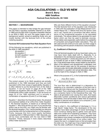
AGA CALCULATIONS — OLD VS NEWBrent E. BerryABB-TotalflowPawhusk Road, Bartlesville, OK 74005SECTION 1 — BACKGROUNDThis paper is intended to help bridge the gap betweenthe Old AGA-3 equation (hereafter referred to as AGA3-1985) and the New AGA-3 equation (hereafter referredto as AGA-3-1992). As such the paper begins with abackground section aimed at assisting those who aremostly familiar with the factored form of the orificemetering equation.Factored VS Fundamental Flow Rate Equation FormOf the following two equations, which are published inthe AGA-3-1985 standard?(a) equation 1(b) equation 2(c) both equation 1 and 2(d) don’t knowCdQV 1–β4Y π d 2 2 gc ρf P4ρbQv C’ hw Pf(eq 1)where,C’ Fb Fr Y Fpb Ftb Ftf Fgr Fpv(eq 2)The correct answer is (c). Both equations are actuallypublished in the 1985 standard and they are bothequivalent within their scope of applicability. Equation 2is often referred to as the factored form of the AGA-3equation. It can be found on page 38 of the 1985standard as equations (59) and (60). Equation 1 is thefundamental orifice meter equation. It can be found onpage 25 of the 1985 standard and is actually acombination of equations (3) and (7) on that page.Equation 1 describes the theoretical basis, the physicaland practical realities of an orifice flow meter. Equation2, the factored equation, is based on or derived fromequation 1. Why bring all this up now? If you are like thisauthor was at one time, you might only be familiar withthe factored equation. If so, I recommended you becomemore familiar with the fundamental form of the equation.Firstly, because this form more readily facilitatescomparing AGA-3-1985 and AGA-3-1992. Secondly, youwill be more comfortable with the new AGA-3-1992standard. Thirdly, because it more clearly describesorifice meter dynamics.PAGE 1722002 PROCEEDINGSAMERICAN SCHOOL OF GAS MEASUREMENT TECHNOLOGYWhy are there different forms of the equation anyway?The first factored form of the equation was introducedin 1935 with the publication of Gas Measurement Committee Report No. 2. Before that time the factors werenot in use. Factors are a convention that allow variousterms of the fundamental equation to be calculatedindividually. This allows tables to be generated for eachfactor which can then be used to estimate volumes.These tables were especially useful before the availabilityof computers and programmable calculators. They arestill used and will continue to be used, but their usage isdiminishing with the advent of electronic instrumentation.Cd, Coefficient of DischargeIf the old factored equation is all you have been using, youmay have never really dealt with Cd. Basically, Cd isimbedded in the old factored equation as part of (Fb * Fr).Reviewing equation 1 of this document you will notice Cdis included as part of AGA-3-1985’s fundamental equation. It has always been there, simply hidden by the factors.Most of the research and development undertaken overthe last several years was for the purpose of deriving amore accurate, technically defensible correlation betweena published Cd equation and actual laboratory data. Thisis at the heart of the changes in AGA-3-1992.What is the purpose of Cd in the fundamental equation?Cd true flow ratesppitheoretical flow rateThe true flow rate is determined in a laboratory byweighing or by volumetric collection of the fluid over ameasured time interval and the theoretical flow rate iscalculated. Then a discharge coefficient (Cd ) is computedas a correction factor to the theoretical flow rate. Thisdata is all generated over varying flow rates, fluid types(Reynolds number conditions) and various geometries(diameters). Once all the data is taken then an empiricalequation is derived which allows us to compute Cd overmany combinations of conditions.That is what Cd, the coefficient of discharge is. It is ahigh falutin’ fudge factor. The developers of the newequation have taken advantage of newer technology inmore numerous testing labs to gather more real worlddata over a wider set of operating conditions. They havealso postulated on a new form of the Cd equation thatthey believe more closely correlates to the fluid dynamicsassociated with the physics of an orifice meter. Thismeans the new Cd is based more on first principles thanthe older one. You might say it has a higher falutin’ indexthan the older coefficient of discharge.
Why does the theoretical equation not match the realworld exactly?In trying to keep orifice metering practical, simplifyingassumptions are sometimes made. It is simply not alwayspossible, practical or necessary to perfectly model thereal world. Some of the things influencing the theoreticalequation, causing it not to model the real world exactlyare:(1) It is assumed there is no energy loss between thetaps.(2) The velocity profile (Reynolds number) influences arenot fully treated by the equation. It is assumed thatsome installation effects and causes of flow perturbations (changes) are insignificant.(3) Different tap locations affect the flow rate. Taplocation is assumed for a given Cd.Through rigorous testing, you could develop a uniqueCd for each of your orifice meters. This technique, referredto as in-situ calibration, is something like proving a linearmeter. However it is somewhat bothersome since youneed a unique Cd for each expected flow rate. Economicsusually make in-situ procedures unfeasible.Therefore, the goal is to develop a universal Cd thateveryone can use. To accomplish this, one must controltheir orifice meter installation well enough so that itreplicates the same orifice meters used in the laboratoryfrom which the universal Cd equation was derived. Thisis referred to as the law of similarity. If your orifice metersystem is acceptably similar to the laboratory’s then yourCd will be acceptably similar to the laboratory derivedC d. That is why edge sharpness, wall roughness,eccentricity and flow conditioning, etc. are so important.Ideally your flow measurement system would be exactlythe same as was used in the laboratory.DensityIf the old factored equation is all you have been using,you may have never really dealt with density. Lookingback at Equation 1 of this document you will notice twosymbols, ρf and ρb. The symbol ρ (pronounced rho) isused to represent density.ρf density at flowing conditionsρb density at base conditionsDensity at Base Conditions(eq. 4)Notice Pf, Tf, Zf, Gi, Pb, Tb, and Zb in eq 3 and eq 4. Theserepresent temperatures, pressures, specific gravities andcompressibilities. It is these variables that eventuallymake there way into the old factors Ftb, Fpb, Ftf, Fgr, andFpv (see Section 3 of this document for more information).Leaving densities in the fundamental equation, ratherthan hiding them in a plethora (abundance) of factors,seems less confusing and more instructive.Real VS Ideal Gas Specific GravityOne other item of note regarding the density equationsis that they are based on Gi , ideal gas specific gravity.Most systems have historically provided Gr , real gasspecific gravity, which is different. Additionally AGA-8requires Gr as an input, not Gi . Strictly speaking,Gi isrelated to Gr with the following equation.Practically speaking the measurement system does notusually have enough information available to solve theabove equation. Part 3 of the new standard makes thefollowing statements regarding this issue.“the pressures and temperatures are defined to be atthe same designated base conditions.”. And again in afollowing paragraph, “The fact that the temperature and/or pressure are not always at base conditions results insmall variations in determinations of relative density(specific gravity). Another source of variation is the useof atmospheric air. The composition of atmospheric air —and its molecular weight and density — varies with timeand geographical location.” 3Based on this, and several of the examples in the standard, the following simplifying assumptions are made:Most measurement systems do not have density as alive input, so density is computed from other data that isavailable. When the fluid being measured is a gas, densityis computed from other data as follows:Density at Flowing Conditions(eq. 3)(eq. 5)This equation for Gi is exactly like the one shown asequation 3-48 on page 19 of Part 3 of the new standard.2002 PROCEEDINGSPAGE 173AMERICAN SCHOOL OF GAS MEASUREMENT TECHNOLOGY
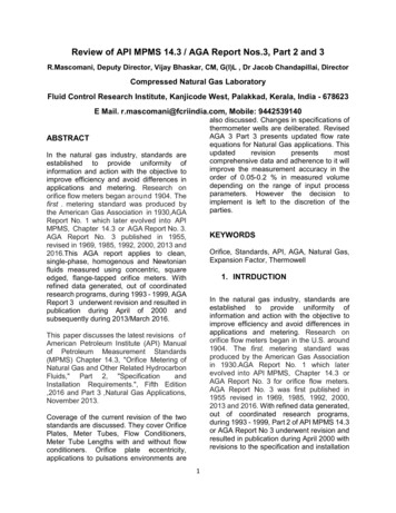
ConclusionTABLE 2-1Fundamental Equation Nomenclature ChangesThese are the major new equation concepts you mightneed to learn if the older factored equation is all you arefamiliar with. A more detailed comparison between thefundamental equation and the factored equation ispresented in Section 3. The following section summarizeschanges to the new standard.SECTION 2 — SUMMARY OF CHANGES TO THESTANDARDChange 1, Document OrganizationRather than one document, the standard is nowpublished in 4 parts, each of which is a unique document.AGA-3-1985Equationvelocity -1992EquationVelocity ofApproachSymbolNumericConstant*Part 1 – General Equations and Uncertainty Guidelines*Nc is combined with other constants before solving the equation.These other constants are a function of the system of units chosen.The mass and volumetric flow rate equations and theirtheory are discussed. The empirical equations for Cd andY are presented. Uncertainty guidelines are presentedfor determining possible errors associated with using thestandard.physics of an orifice meter you would not expect it tochange. However, nomenclature was slightly modified.eq. 1, AGA-3-1985 Fundamental EquationPart 2 – Specification and Installation RequirementsMechanical specifications are presented for the orificemeter. In particular orifice plates, plate holders, sensingtaps, meter tubes and flow conditioners are discussed.eq. 7, AGA-3-1992 Fundamental EquationPart 3 – Natural Gas ApplicationsThe fundamental equation, as presented in Part 1, is notrestricted to a specific fluid or system of units. Part 3provides a guide for forcing the equation to computevolumes assuming the fluid is natural gas and the inchpound system of units. It is in appendix B of this partthat a factored form of the equation is developed.Part 4 – Background, Development, ImplementationProcedures and Subroutine DocumentationThe history and evolution of the equation is included inthis part beginning with Report No. 1 from the 1920s. Adescription of the research that was undertaken to derivethe new equation is presented. Implementation procedures, guidelines, and subroutine recommendations arealso documented to assist programmers with implementing the new equation on computers. Intermediate resultsare also available to assist with program verification.Inclusion of computer related documentation of this sortis completely new for the AGA-3 standard and recognizesboth the need for a computer to solve the new equationand the availability of computers to accomplish this.Change 2, The nomenclature of the fundamental equationwas modified slightly.It is important to note that the fundamental equation didnot actually change. Since it is based on the actualPAGE 1742002 PROCEEDINGSAMERICAN SCHOOL OF GAS MEASUREMENT TECHNOLOGYChange 3, Cd — New coefficient of discharge solutionrequires an iterative solutionAs was stated earlier, Cd is at the heart of the changesfor AGA-3-1992. Many people spent substantial time andeffort in various countries conducting tests to providenew data that could be used to empirically derive a better,more technically defensible coefficient of discharge.Once the data was gathered and accepted, talentedpeople, using computers, derived a Cd equation that hasa high degree of correlation with all the new data. Thismeans that, within the stated uncertainties of Part I ofthe new standard, you can feel confident that whenapplied as specified by the standard, the new Cd equationwill produce dependable answers.The tricky part about Cd is that one needs to know theflow rate to compute it. But one also needs the Cd tocompute the flow rate. This is a sort of catch 22. In asituation like this we say the equation is not in closedform. This is why you will hear people say an iterativesolution is required to compute the new Cd.What does iterative solution mean? It means you, (or morelikely a computer) begin with an estimate for Cd. Basedon that Cd, an estimated Reynolds Number, Flow Rate and
a subsequent new Cd are computed. The two Cd values(Cd old and Cd new) are compared and if they differ bymore than an acceptable threshold, the process isrepeated. Each time the process is repeated the mostrecent Cd is retained for comparison with the next onebeing computed. Eventually, the difference betweenC d old and C d new become so small it is safe toassume the proper Cd value has been obtained. APIdesigners estimate that, most of the time, no more thanthree iterations will be required. I believe no more than10 iterations were ever required on the test cases. Anexact procedure is outlined in Part 4 of the new standardunder Procedure 4.3.2.9. In that procedure the thresholdfor determining acceptable convergence is six significantdigits (0.000005).Change 4, Thermal effect corrections on Pipe and Orificediameters are requiredIn the AGA-3-1985 standard an optional orifice thermalexpansion factor, Fa , was specified to correct for the errorresulting from thermal effects on the orifice plate diameter.In the AGA-3-1992 standard this type of correction isnot optional. It is required. Additionally you must alsomake corrections for thermal effects on the pipe diameter.Another new requirement is that these corrections cannotbe tacked onto the end of the equation as a factor. Theyare to be applied on the front end as adjustments to thediameters themselves. Therefore, the end user shouldbe supplying diameters at a reference temperature(68 DegF), and the device solving the equation shouldbe adjusting the diameters based on the differencebetween the re
AGA CALCULATIONS — OLD VS NEW Brent E. Berry ABB-Totalflow Pawhusk Road, Bartlesville, OK 74005 SECTION 1 — BACKGROUND This paper is intended to help bridge the gap between the Old AGA-3 equation (hereafter referred to as AGA-3-1985) and the New AGA-3 equation (hereafter referred to as AGA-3-1992). As such the paper begins with a background section aimed at assisting those who