Transcription
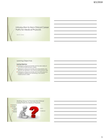
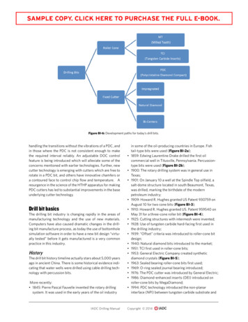
BITSBI–5Figure BI-6: Development paths for today’s drill bits.handling the transitions without the vibrations of a PDC, andin those where the PDC is not consistent enough to makethe required interval reliably. An adjustable DOC controlfeature is being introduced which will alleviate some of theconcerns mentioned with earlier technologies. Further, newcutter technology is emerging with cutters which are free torotate in a PDC bit, and others have innovative chamfers ora contoured face to control chip flow and temperature. Aresurgence in the science of the HTHP apparatus for makingPDC cutters has led to substantial improvements in the baseunderlying cutter technology. Drill bit basics The drilling bit industry is changing rapidly in the areas ofmanufacturing technology and the use of new materials.Computers have also caused dramatic changes in the drilling bit manufacture process, as today the use of bottomholesimulation software in order to have a new bit design “virtually tested” before it gets manufactured is a very commonpractice in this industry.HistoryThe drill bit history timeline actually stars about 5,000 yearsago in ancient China. There is some historical evidence indicating that water wells were drilled using cable drilling technology with percussion bits.More recently: 1845: Pierre Pascal Fauvelle invented the rotary drillingsystem. It was used in the early years of the oil industryIADC Drilling Manual in some of the oil-producing countries in Europe. Fishtail-type bits were used (Figure BI-2a);1859: Edwing Laurentine Drake drilled the first oilcommercial well in Titusville, Pennsylvania. Percussiontype bits were used (Figure BI-2b);1900: The rotary drilling system was in general use inTexas;1901: On January 10 a well at the Spindle Top oilfield, asalt-dome structure located in south Beaumont, Texas,was drilled, marking the birthdate of the modernpetroleum industry;1909: Howard R. Hughes granted US Patent 930759 onAugust 10 for two cone bits (Figure BI-3);1910: Howard R. Hughes granted US. Patent 959540 onMay 31 for a three-cone roller bit (Figure BI-4);1925: Cutting structures with intermesh were invented;1928: Use of tungsten carbide hard-facing first used inthe drilling industry;1939: “Offset” criteria was introduced to roller-cone bitdesign;1940: Natural diamond bits introduced to the market;1951: TCI first used in roller-cone bits;1953: General Electric Company created syntheticdiamond crystals (Figure BI-5);1963: Sealed bearing roller-cone bits first used;1969: O-ring sealed journal bearing introduced;1976: The PDC cutter was introduced by General Electric;1986: Diamond-enhanced inserts (DEI) introduced onroller-cone bits by MegaDiamond;1994: PDC technology introduced the non-planarinterface (NPI) between tungsten carbide substrate andCopyright 2014
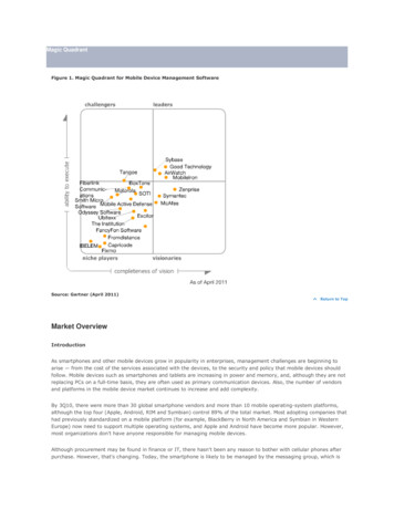
BI–6BITSFigure BI-7: The bit cone’s “offset” is the horizontal distance between the bit axis and a vertical plane through the axis of the journal.Soft formations usually experience a high offset, while hard formations usually have a low offset. Courtesy Schlumberger. 2013: Rotating PDC cutter and a PDC cutter with acontoured face to improve chip flow and run cooler.Drilling bits classificationThere are two big groups of drilling bits, including its respective divisions and sub-divisions, as follows:The PDC bits can be sub-classified as: Matrix-body PDC; Steel-body PDC.The same type of sub-classification applies to bi-center bits: Matrix-body bi-center; Steel-body bi-center.Also, impregnated bits can be sub-classified as: Conventional impregnated matrix; Impregnated inserts or segments.Note: Matrix is manufactured from a tungsten carbide powder and metallic binder.Design basicsBased on the drilling mechanics differences between rollercone bits and diamond bits, different design concepts applyfor each group of bits.Roller-cone bitsThere are three basic design factors for roller-cone bits: Cone offset; Journal (bearing pin) angle; Cone profile.Figure BI-8: The top image shows a low offset, while the lowerdrawing shows a high offset. Notice the difference between thecenterline and the offset on each cone. Courtesy Schlumberger.diamond table. Diamond table thickness was increasedto maximize wear resistance and cutter life; 1995: Polished cutters, stress engineered cutterplacement and application-specific cutters introducedcommercially; 2003: Surface-leached PDC cutters commercialized; 2003: Depth of cut control for steerable PDC introduced;IADC Drilling ManualOffsetThe bit cone’s “offset” is defined as the horizontal distancebetween the axis of the bit and a vertical plane through theaxis of the journal.Offset is established by moving the centerline of a coneaway from the centerline of the bit in such a way that a vertical plane through the cone centerline is parallel to the vertical centerline of the bit.Copyright 2014
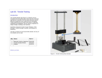
BITSBI–7Figure BI-9 (above): The journal angle is formedby a line perpendicular to the bit axis and thejournal axis. Courtesy Schlumberger.Figure BI-10 (top and center right): Usually bits withsmaller journal angles (30 -33) are best for drillingsofter formations requiring lower WOB. Conversely,larger journal angles are better for harder formationsrequiring higher WOB. Courtesy Schlumberger.Soft formations usually experience a high offset (3 8 in.),while hard formations usually have a low offset (1 32 in.).Soft formation bits use high offsets values to increase thiscutting action and thus increase ROP, while harder bits uselower offsets values to reduce cutter wear induced by thesliding action. Gauge contact and length;Cone diameter;Cone shell thickness;Bearing space availability;Leg strength.These images show a low offset (up) and a high offset(down). Notice the difference between the centerline andthe offset on each cone.It also affects the relationship between scraping and crushing actions produced by the cutting elements of the bit.Basic cone geometry directly affects increases or decreasesin either journal or offset angles and a change in one of themrequires a compensating change in the other.Generally, bits with relatively small journal angles, 30 -33 ,are best suited for drilling in softer formations that requirelower weight on bit (WOB). These formations require gouging and scraping actions.Journal (bearing pin) angleThe journal angle is the angle formed by a line perpendicularto the axis of the bit and the axis of the journal. Journal angleinfluences the design of many key bit features, including: Intermesh depth; Insert projection and milled tooth depth; Heel surface length and angle;IADC Drilling ManualSoft formations: low journal angleHard formations: high journal angleLarger journal angles, 34 -39 , are better when drilling inharder formations that require higher WOB amounts. Hardformations require a chipping and crushing action.Copyright 2014
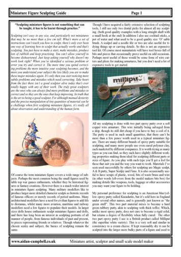
BI–8BITSFigure BI-11: The basic design factors associated with designing bits for particular formation types. In a very soft formation, forinstance, the bit teeth are spaced farther apart, are longer and gouge and scrape more than chip or crush. Courtesy Schlumberger.Figure BI-12: Roller-cone bits boast one of the highest unitloads for any bearing and require specialized grease.Design factors summaryFigure BI-11 identifies the basic design factors associatedwith designing a bit for a particular type of formation. Forexample, in a very soft formation, the teeth of the bit arespaced further apart, longer in length and provide moregouging-scraping action; the journal angle is lower, while theoffset is higher.Figure BI-13: Seals contribute significantly to the effectiveness ofthe lubrication and pressure compensation system by preventingdrilling contaminants from entering the bearings. Non-sealedbearing designs allow mud to enter the bearing to cool andlubricate, but suffer shorter bearing life than sealed bearings.Lubrication and pressure compensationsystemRoller coneThe lubrication and pressure compensation system equalizes pressure across the seal and provides lubricant to optimize temperature and load pressure within the bearingsystem. Roller-cone bits have one of the highest unit loadsof any bearing and require specialized grease. Each drill bitmanufacturer has developed custom-engineered roller conebearing grease compatibility with all bearing components.The grease has been designed to have higher heat capacity, greater resistance to oxidation, and higher load capacityIADC Drilling ManualCopyright 2014
BITSBI–9than conventional bearing greases. Collectively these characteristics minimize wear and friction and extend the life ofthe bearing system.The pressure compensation system serves to accommodategrease expansion, cone movement and annulus pressureand maintain a stable environment for the bearing system.The seal contributes significantly to the effectiveness of thelubrication and pressure compensation system as its dynamic properties keep drilling contaminants from enteringthe bearings.Figure BI-14: The apex is the geometric center of a diamond bit. Thecone can have a deep or shallow profile. Courtesy Schlumberger.The pressure compensation system has a diaphragm thatmoves inwards to equalize internal pressure with the outsidepressure from the annulus or changes in volume from conemovement. The diaphragm moves outward to increase theinternal volume from grease expansion and cone movementto equalize with external pressure. In doing so, grease canvent through the diaphragm into the annulus to equalize thepressure.Some bearing designs incorporate solid lubrication components such as thrustwasher or hardmetal inlays; othersincorporate a silver-plated bearing surface. These components serve to form a dissimilar material system that mitigates adhesive wear when carrying the thrust component ofthe bearing load. These run against Stellite inlays, in manycases, which also provide a dissimilar material system thatmitigates adhesive wear. The inlays have higher wear resistance properties than steel so as to reduce bearing letdown.Not all roller cone drill bits have sealed bearings. Non-sealedbearing designs allow mud to enter the bearing for coolingand lubrication. Non-sealed designs have a shorter bearinglife than sealed bearings as mud contains particles that cancause excessive wear to the bearings therefore shorteningthe bearing in comparison to sealed designs.Diamond bitsFigure BI-15: A bit’s nose is described by the radius (R) of it’scurvature and the horizontal distance (L) from the bit centerlinewhere the curvature begins. Courtesy Schlumberger.Figure BI-16a & 16b: The bit above features a nose locationclose to the apex. This means higher cutter density on theshoulder. Therefore, there is more diamond volume, creating abit suitable for abrasive formations. Courtesy Schlumberger.Bit profileThe first factor is the bit profile, which is a vertical cross-section of the bit head.The profile has a direct influence on stability, steerability,cutter density, durability, ROP, cleaning efficiency and cuttercooling.The profile is divided as follows:The apex is the geometrical center of the bit.The cone area can be: Deep cone profile;IADC Drilling ManualFigure BI-17a & 17b: When the nose moves further fromthe apex, higher cutter density exists along the cone.This increases cone durability, suitable for drilling strongformations, such as dolomite and limestone, as wellas transitional drilling. Courtesy Schlumberger.Copyright 2014
PDC cutters has led to substantial improvements in the base underlying cutter technology. Drill bit basics The drilling bit industry is changing rapidly in the areas of manufacturing technology and the use of new materials. Computers have also caused dramatic changes in the drill-ing bit manufacture process, as today the use of bottomholeFile Size: 1MBPage Count: 5