Transcription
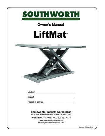
Owner’s ManualDL Series Lift TablesModel #Serial #Date placed in ServiceSOUTHWORTH PRODUCTS CORPP.O. Box 1380 Portland, ME 04104-1380Telephone: (207) 878-0700 or (800) 743-1000Fax: (207) 797-4734www.SouthworthProducts.comEmail: service@SouthworthProducts.comRevised February 2013
Please note: This manual was current at the time of printing.To obtain the latest, most updated version, please contact Southworth’s Customer Service Department or go to our website:www.SouthworthProducts.com, under Parts & Serviceyou will find a complete list of currentowner’s manuals to print.
ContentsINTRODUCTION. 1RESPONSIBILITY OF OWNERS AND USERS . 2SAFE SERVICING OF THE LIFT . 3SAFETY PRECAUTIONS . 4INSTALLATION INSTRUCTIONS . 4Preparation . . 4Positioning the Lift .5Hydraulic Connections . . 5Electrical Connections . . 6Completing Installation .7OPERATING INSTRUCTIONS . 8Labels and Precautionary Markings . . 8Operating Procedure . . 9MAINTENANCE . . 10Hazards .10Routine Periodic Maintenance . 10Repacking Cylinders. 11Replacing Leg Rollers. 12Troubleshooting Check List . 14-15ORDERING REPLACEMENT PARTS . . 16WARRANTY. Back CoverList of FiguresFig. 1 Safe Servicing of Lift . 3Fig. 2 Mount the Lift Securely . 4Fig. 3 Using Lifting Eyes . . 5Fig. 4 Center the Load . 7Fig. 5 Secure the Load . . 7Fig. 6 Labels and Precautionary Markings . . 8Fig. 7 Pinch Points . 9Fig. 8 J-Style Cylinder . 12Fig. 9 Parts Identification . 13Fig. 10 Standard 3.2 HP Power Unit . 17Fig. 11 Hydraulic Pump and Down Valve . 17Fig. 12 Electrical Connections,Lifts Wired for Single-Phase AC . 18Fig. 13 Wiring Diagram,Lifts Wired for Single-Phase AC - without limitswitch . 18Fig. 14 Electrical Connections,Lifts Wired for Single-Phase AC - with limitswitch . 19Fig. 15 Schematic, Lifts Wired for Three-Phase AC. 20Fig. 16 Hydraulic Connections. 20Fig. 17 Hydraulic Diagram . 21Table 1 Hydraulic Oil Specifications . 6Table 2 Electrical Interface, Supplied by Customer. 21
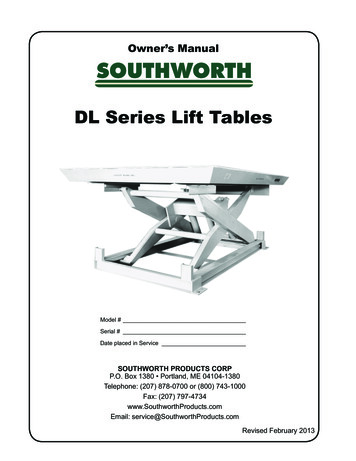
SOUTHWORTHINTRODUCTIONThe DL series includes Southworth’s “heavy duty” hydraulic tables. The basic DLseries lift may be modified in many ways to meet special requirements for loadcapacity, vertical travel, table size, power source, and other characteristics. DLlifts can also be fitted with many optional accessories and modifications to suit thecustomer’s needs.This manual contains information to acquaint you with the safe and properinstallation, use, and upkeep of an DL series lift table. You should ensure that thismanual is available to personnel working with and on the lift table and require itsuse by these personnel.DL lift tables are designed for lifting and vertical positioning of equipment andmaterials in a wide variety of industrial settings. The instructions set forth in thismanual are not necessarily all-inclusive, as Southworth cannot anticipate allconceivable or unique situations.In the interest of safety, please read all of this manual carefully, and befamiliar with its contents before you install, use, or service the DL Lift Table.If you have any questions about any of the instructions in this manual, pleasecontact your dealer or Southworth Products Corp.Southworth’s product warranty is shown on the back cover of this manual.This instruction manual is not intended to be or to create any other warranty,express or implied, including any implied warranty of merchantability orfitness for a particular purpose, all of which are hereby expressly excluded.As set forth more specifically in the product warranty, Southworth’s obligation underthat warranty is limited to the repair or replacement of defective components,which shall be the buyer’s sole remedy, and Southworth shall not be liable forany loss, injury, or damage to persons or property, nor for any direct, indirect, orconsequential damage of any kind resulting from the DL lift table.DL SERIES LIFT TABLES1
DL Series Lift Tables Owner’s ManualResponsibility of Owners and UsersInspection and MaintenanceThe device shall be inspected and maintained in proper working order in accordance withSouthworth’s owner’s manual.Removal from ServiceAny device not in safe operating condition such as, but not limited to, excessive leakage,missing rollers, pins, or fasteners, any bent or cracked structural members, cut or frayedelectric, hydraulic, or pneumatic lines, damaged or malfunctioning controls or safety devices, etc. shall be removed from service until it is repaired to the original manufacturer’sstandards.DeflectionIt is the responsibility of the user/purchaser to advise the manufacturer where deflectionmay be critical to the application.RepairsAll repairs shall be made by qualified personnel in conformance with Southworth’s instructions.OperatorsOnly trained personnel and authorized personnel shall be permitted to operate the lift.Before OperationBefore using the device, the operator shall have: Read and/or had explained, and understood, the manufacturer’s operating instructions and safety rules. Inspected the device for proper operation and condition. Any suspect item shall becarefully examined and a determination made by a qualified person as to whetherit constitutes a hazard. All items not in conformance with Southworth’s specificationshall be corrected before further use of the equipment.During OperationThe device shall only be used in accordance with this owner’s manual. Do not overload. Ensure that all safety devices are operational and in place.Modifications or AlterationsModifications or alterations to any Southworth industrial positioning equipment shall bemade only with written permission from Southworth.2DL SERIES LIFT TABLES
SOUTHWORTHSAFE SERVICING OF THE LIFTWARNING !Only authorized personnel should performinspection or maintenance and service procedures. Unauthorized personnel attemptingthese procedures do so at the risk of severeinjury or death.DANGER !Failure to properly adhere to lift blockingprocedures is to risk the sudden and uncontrolled descent of the lift during maintenanceor inspection. A falling lift can cause severeinjury or death.This procedure describes the only factory-approved methodof working under a lift. Follow these instructions EVERY timeyou plan to reach or crawl beneath the lift to perform service ormaintenance – no matter how momentary that might be.If the factory-provided maintenance device is damaged ormissing, stop immediately and consult the factory for assistance.The manufacturer is not liable for your failure to use the approvedmaintenance device(s) and procedures that have been provided.1. Any load must be removed from the lift prior to engaging themaintenance device(s). These devices are designed to supportan unloaded lift only. Failure to remove the load from the liftprior to blocking could cause the failure of the maintenancedevice(s) and allow the lift to fall unexpectedly. This can result in personal injury or death, or permanent damage to themaintenance device(s) and/or the lift.2. Raise the lift to its fully raised position. If you do not, themaintenance device(s) may not be able to be placed properlyin its/their designed blocking position.3. Remove the maintenance device(s) from its/their storage location and place it/them into the engaged position as shownin Figure 1. (Note: further information may be useful here toprovide additional instructions as to the location and methodof storage and engaged positions).4. Lower the lift until it makes complete contact with the maintenance device(s). Re-check to ensure that all provided devicesare fully and securely engaged. If the device(s) is/are not fullyengaged the lift could fall unexpectedly, resulting in permanentdamage to the device(s) or the lift.Rotate the chocksinto ionFigure 1 – Safe Servicing of Lift5. (For single-acting hydraulic, and pneumatic lifts) Once the maintenance device(s) is/are properly and securely engaged, continueto press the down button, valve or switch for an additional 5-10seconds to relieve all pressure in the operating system (addmore specifics here as required for pneumatic lifts).WARNING !Failure to relieve operating system pressurecould result in the sudden and unexpectedrelease of high pressure fluids (or air) duringmaintenance and/or repair of the lift and resultin severe injury or death.6. Follow OSHA electrical lock-out/tag-out procedures. Disconnectand tag all electrical and/or other power sources to prevent anunplanned or unexpected actuation of the lift.7. Once inspection or work is complete, reverse the performanceof the steps above to raise the lift off the maintenance device(s)and place the device(s) back into its/their designated storageposition(s).DANGER !HIGH VOLTAGE ! – Disconnect and/or lockout the electrical supply to the power unitprior to any installation or maintenance beingperformed.DANGER !If for any reason you are unable to lower thelift completely onto the maintenance device(s),stop immediately and consult the factory.Failure to properly use the factory approvedmaintenance device(s) could result in severeinjury or death.DL SERIES LIFT TABLES3
DL Series Lift Tables Owner’s ManualSAFETYThe safety of all persons operating, maintaining,repairing, or in the vicinity of the DL lift table is ofparamount concern to Southworth. The lift table is apowerful machine with moving parts, and is capableof causing personal injury if proper precautionsare not taken.including all safety instructions and precautions,carefully and completely.INSTALLATIONINSTRUCTIONSTherefore, throughout this manual, Southworth hasidentified certain hazards which may occur in the useof the lift table, and provided appropriate instructionsor precautions which should be taken to avoid thesehazards.PreparationIn some cases, Southworth has also pointed out theconsequences which may occur if Southworth’sinstructions or precautions are not followed. Southworthuses the following system of identifying the severity ofthe hazards associated with its products:Read all of these installation instructions carefully. Besure to read and understand all of the warnings!“DANGER” - Immediate hazard which willresult in severe personal injury or death.“WARNING” - Hazard or unsafe practicewhich could result in severe personal injuryor death.“CAUTION” - Hazard or unsafe practicewhich could result in minor personal injuryor property damage.Please read and follow this instruction manual,Before you start to install the lift, check for local codesand ordinances which may apply. It is your responsibilityto obtain any necessary permits.If your unit is designed to be installed in a pit, check thepit before you start to install the lift. Measure the lengthand width of the lift table, then measure the pit, and besure the pit allows adequate clearance. Does the pithave 90 angles at each corner? To check, measureacross the opposite corners of the pit. The measurementon each diagonal should be the same, within 1/2 inch.The walls of the pit should be vertical. Check with acarpenter’s square.If the power unit will be mounted away from the lift(“external power unit”), check the mounting arrangementfor the power unit. The power unit should be shelteredfrom the weather. It should be mounted within 30 feetNote: Certain DL models, including dock lifts, require handrails.Throughout this manual, the handrails have been omitted for clarity.Use lag bolts to hold the unit down(unless it is mounted on casters).If necessary, insert shimsto level the lift.Grout or shim the area under eachside rail with cement.The side rails must be supported.Mount the lift on a firm,level surface.Fig. 2 – Mount the Lift Securely4DL SERIES LIFT TABLESLag plates
SOUTHWORTHFig. 3 – Using Lifting EyesThe chain should pull straight upChain spreader barEye boltCaptive nutBase nutof the lift to minimize the pressure drop in the hydraulicsystem. Be sure the hydraulic lines have been installedproperly.WARNING!Protect the power unit from rain or moisture.If the electrical parts in the power unit getwet, workers may be hurt by electricalshock. The electrical parts may fail if theyare wet.WARNING!The electric motor in the lift can createsparks. Don’t install the power unit inan area where flammable gases may bepresent.If the power unit is mounted within the lift (“internalpower unit”), you will need these tools: A crane or lift truck that can lift the unit safely. Shims and lag bolts – see the pit plan if the lift willbe mounted in a pit. A masonry drill and bit to drill the holes for the lagbolts. A power supply with the specified voltage, includingfuses or circuit breakers as specified in Figures 12,13 and 14.If the power unit will be mounted away from the lift(“external power unit”), you will also need: A compressed air source for clearing the hydrauliclines. Extra hydraulic oil for flushing the undergroundlines and refilling the tank. See Table 2 for the oilspecifications.Positioning the LiftRemove the shipping material and unskid the lift. On thefront of this manual, confirm the model number, serialnumber, and date the lift is placed in service. You canfind the model number and serial number on the nameplate. The name plate is located on the crossbar at thebase of the cylinders.Move the lift into position, supporting the base of thelift. If the lift has a hinged throwover plate, set the lift inposition so the plate is in the appropriate orientation.Install the lift as shown in Figure 2. Unless the lift ismounted on casters, lag the lift to the floor.CAUTION!Do not hang the lift from the table top. Thiscan damage the lift.WARNING!If the lift is mounted on an unstable surface,it may tip over when it is in use. You maybe hurt, and the lift and load may bedamaged.If your lift has lifting eyes, as shown in Figure 3, usethese when you move the lift. It is best to use a chainspreader, so the chain sections pull straight up. (Youmust supply the chain and spreader.) Remove the liftingeyes once you have moved the lift.Hydraulic Connections(External Power Units Only – If Internal Power Unit,proceed to step 10.)Install the power unit. Install the hydraulic line betweenthe power unit and the lift as shown on the pit plan.Blow out the hydraulic line with compressed air beforeDL SERIES LIFT TABLES5
DL Series Lift Tables Owner’s Manualconnecting it to the lift table. Replace the solid plug onthe hydraulic fluid tank with the vented plug supplied,then attach the vent line to the vented plug.WARNING!Be sure that the hydraulic line will not bepinched by the lift as it raises or lowers. Ifyou allow the line to be pinched, the lift maynot work properly. A hose may break, thelift table may drop suddenly, and someonemay be hurt.Electrical ConnectionsDANGER!The lift may use a power supply of up to 575Volts AC. This voltage can kill you. Do notwork with the electrical parts unless you area qualified electrician.Make temporary electrical connections to the lift, asshown in Figure 13 through 15. This temporary set-upwill allow you to raise the lift.CAUTION!It is very important to keep the hydraulicoil free of dirt, dust, metal chips, water, andother contamination. Most of the problemswith hydraulic systems are caused bycontamination in the oil. Be sure to flush allhydraulic lines before connecting remotepower units.CAUTION!If you do not install the vented plug in thetank, the pump may be damaged.Table 1 – Hydraulic Oil SpecificationsIf the lift will be used at normal ambient temperatures,Southworth supplies the unit with CONOCO 32 oil. Thismay be replaced by any other good quality oil with 150SSU at 100 F and rust and oxidation inhibitors andanti-wear properties. If the lift will be used at ambienttemperatures below 0 F, use aircraft hydraulic oil. UseType 15 aircraft hydraulic oil.The following are equivalent to CONOCO 32:TYPE .MANUFACTURERDTE 24 .EXXON/MOBILWARNING!The fusing requirements are shown inTable 1. To avoid fire danger, follow theserequirements.On a lift designed for three-phase AC, you must be surethe pump motor is turning in the right direction. The lifttable should start to move quickly when you press the“up” or “down” button. If the lift table does not move in2 or 3 seconds, do not try to operate the lift! Exchangeany two of the three-phase leads. If this does not correctthe problem, see the troubleshooting instructions at theend of this manual.CAUTION!If you have a unit designed for three-phaseAC and you connect the power so the motorruns backwards, the lift will not operate, andyou may damage the pump. Do not operatethe lift for more than 2 or 3 seconds if youthink the motor might be turning backwards.Raise and chock the lift, as shown in Figure 1.Make the permanent electrical connections as shownin Figure 13 through 15.Check the level of the hydraulic fluid. On most models,when the lift is fully elevated, the oil should be about3/4 inch above the bottom of the tank. Use a dipstick tocheck the oil level, and add oil as necessary.NUTO H32 .EXXON/MOBILAMOCO AW32 .CHEVRON (AMOCO CO.)CITGO AW32.CITGOCAUTION!It is very important to keep the hydraulicoil free of dirt, dust, metal chips, water, andother contamination. Most of the problemswith hydraulic systems are caused by contamination in the oil.6DL SERIES LIFT TABLESTestingClear the area around the lift. Remove any loose wires,lumber, or other materials which might get in the way ofthe lift as it raises or lowers.Remove the maintenance chocks and warn others tostay away from the lift. Operate the lift through its fullrange of travel. The lift should rise smoothly with a quiethumming sound, and lower smoothly and quietly. Raiseand lower the lift a few times to check the clearancesaround the lift table.
SOUTHWORTHWARNING!As the lift table moves up and down, “pinchpoints” are created at the places shown inFigure 6. If you are standing too close to thelift when it is moving, your arm or leg may becaught in the moving parts, and you may behurt. Stay away from the pinch points whenthe lift is moving.Completing InstallationIf your lift is mounted in a pit, align the unit with thesides of the pit. Once you are sure the lift is positionedcorrectly, mark the locations of the lag holes in the baseframe, and drill the holes. If necessary, insert metalshims to level the base of the lift. Insert and tighten thelag bolts to secure the lift. Grout under the base rails toprevent vibration and distortion of the base frame, asshown in Figure 2.If the lift is lowering too quickly or too slowly, you canchange the “down speed” by adjusting the flow control.The flow control may be mounted either internally, at thebase of the cylinders, or on the external power unit.WARNING!When adjusting the flow control, alwaysraise the lift table and insert the maintenancechocks, as shown in Figure 1. Do not try toadjust the flow control while pressing the“down” button. If you try this, the lift tablemay drop suddenly, and you may be hurt.Always place the load in thecenter of the lift tableFig. 4 – Center the LoadIt is important that you follow these steps when adjustingthe flow control: Raise the lift table and insert the maintenancechocks, as shown in Figure 1. If you want the lift to lower more slowly, turn thecontrol clockwise up to 1/4 turn at a time. If youwant the lift to lower more quickly, turn the controlcounterclockwise up to 1/4 turn. Don’t move thecontrol more than 1/4 turn at a time. Remove the maintenance chocks, and check thedescent speed. Every time you want to change the adjustment again,raise the table again and insert the maintenancechocks as shown in Figure 1.Test the lift with the rated load. If the lift does not rise,and you hear a loud squealing noise, the pressurerelief valve is operating. Contact Southworth forinstructions.WARNING!Don’t continue to use the lift if this happens.The pump will overheat very quickly, andmay be permanently damaged. Do not tryto adjust the relief valve. If you change thesetting on the relief valve, you may overworkthe lift. This can cause the lift to fail suddenly, and you may be hurt.As a final step, clean up all spilled hydraulic fluid.Spilled hydraulic oil is slippery, and may present a firehazard.If the load can roll or move,insert chocks, or fastenthe load downFig. 5 – Secure the LoadDL SERIES LIFT TABLES7
DL Series Lift Tables Owner’s ManualOPERATING INSTRUCTIONS1314ItemPart#1 298630659046432 29867373 29869684 2991927LocationOn both sides of platform(use for standard platforms)On both sides of platform(use for platforms with handrails)On upper strongbackOn lower strongbackOn both sides of maintenancechocks, both sides of base5 2991182On both sides of base, as close tomaintenance chock as possible6 2998429On both sides of platform7 2986997On hydraulic tank (not shown)8 Control decals:2986999 (115/1/60)2986998 (24/1/60)5900167 (110/1/50)5900166 (24 VDC)On base end plate, where wire exits the baseItemPart#Location9 Power decals:2987000 (115/1/60)2991783 (12VDC)5900160 (230/1/60)5900161 (24VDC)2987001 (208/3/60)5900163 (110/1/50)2987002 (230/3/60)5900164 (220/1/50)2987003 (460/3/60)2999416 (380/3/50)5900162 (575/3/60)5900165 (415/3/50)On base end plate, where wire exits the base10 2986738On junction box cover(alt: base end plate)11 Capacity decals:2998433 (500#)2998437 (3500#)2998425 (1000#)2998426 (4000#)2998434 (1500#)2998442 (5000#)2998427 (2000#)2998428 (6000#)2998435 (2500#)5900159 (Other)2998436 (3000#)On platform ends, two per end.12 2921026 On both ends of table top13 Fasten to flow control (not shown)14 Fasten to flow control (not shown)Fig. 6 – Labels and Precautionary MarkingsIMPORTANT: Please contact our Service Dept. at 800-743-1000 with any questions regarding the proper placement of labels.8DL SERIES LIFT TABLES
SOUTHWORTHFig. 7 – Pinch PointsOperating ProcedureBefore operating the lift, read and understand this entiresection.DANGER!The lift may use a power supply of up to 575Volts AC. This voltage can kill. Do not workwith the electrical parts unless you are aqualified electrician!Locate the lift on a firm, flat surface as shown in Figure2. Stationary lifts should be lagged to the floor.WARNING!If you place the lift on a soft surface, it maytip over, especially when it is loaded orraised. Someone may be hurt, and the liftand load may be damaged.Load the lift correctly. Be sure that the load weighs no more than themaximum rated for the lift. The maximum rated loadis shown on the platform skirt.WARNING!Do not try to lift a load that exceeds themaximum rating. If you try this, the lift mayfail suddenly. Someone may be hurt, and thelift and load may be damaged. Place the load in the center of the lift table, as shownin Figure 4. Do not try to load the lift while the lift table ismoving. If you are lifting pipes or other objects which maybe able to roll or move, fasten them down, or chockthem as shown in Figure 5.Be sure all workers are clear of the lift. Remove anylumber or other material which may fall onto the lift.WARNING!Do not use the unit to lift people unless it hasbeen specially equipped for this purpose. Aspecially equipped lift will include operatorprotection, and an excess flow protectorto keep the lift from dropping suddenly if ahydraulic line is damaged. Retrofit kits areavailable if you want to add these featuresto your lift.WARNING!As the lift table moves up and down, “pinchpoints” are created as shown in Figure 6.Stay away from these pinch points! Part ofyour body or clothing may become caught,and you may be hurt.Operate the lift. Press and hold the “up” button to raisethe lift, and “down” to lower it. Release the button whenDL SERIES LIFT TABLES9
DL Series Lift Tables Owner’s Manualthe lift reaches the limit of travel. If the lift does notoperate within 2 or 3 seconds, turn off the lift and call aqualified maintenance worker.WARNING!If you hear a squealing noise from thepump, the pressure relief valve is operating.Do not continue to use the lift! The pumpwill overheat very quickly, and may bepermanently damaged. The relief valve isincluded to protect the machine operators– don’t change the relief pressure setting.Wait until the lift table has stopped. Unload the lift.WARNING!The warning labels on the lift are there foryour safety. If you find that the labels areworn or missing, or have been paintedover, ask Maintenance to replace the labelsbefore you use the lift. The labels are shownin Figure 7.MAINTENANCEAll servicing should be done by qualified personnel.Qualified personnel should be able to read andunderstand wiring and hydraulic diagrams. Theyshould be able to troubleshoot live electrical circuitssafely and in accordance with accepted practice. Forsafety’s sake, if in doubt, please contact your dealeror Southworth Products Corp Service Department at(207) 878-0700 or (800) 743-1000.Before servicing the lift, read and understand this entiresection and the section entitled “Operating Instructions.”HazardsThere are several hazards you should be aware of asyou service the lift:DANGER!The lift may use a power supply of up to575 Volts AC. This voltage can kill. Do notwork with the electrical parts unless you area qualified electrician!WARNINGS! As the lift moves up and down, “pinchpoints” are formed as shown in Figure 6.Keep hands, feet, and loose clothing awayfrom these pinch points. If your hand orarm or a part of your clothing is caught, youmay be hurt. A falling lift can cause severe personal10DL SERIES LIFT TABLESinjury. Before working under the lift, raisethe lift and insert the maintenance chocks,as shown in Figure 1. Do this every time youwork under the lift! Do not change the setting on the reliefvalve. If you do change the setting, this maycause a hydraulic part to fail. The hydrauliccomponents in the lift are designed tohandle a certain amount of pressure. If therelief valve does not open, this pressure maybe exceeded. The lift may drop suddenly.Someone may be hurt, and the lift and loadmay be damaged. Release of fluids under high pressurecan cause personal injury. Before you openany part of the hydraulic system, be sure torelease the hydraulic pressure. The warning labels on the lift are there forthe safety of the operators. See Figure 7. If the labels are worn or missing, orhave been painted over, replace them beforereleasing the lift for operation.Routine Periodic MaintenanceEvery month:Visually inspect the leg rollers, center pivot bushingsand pins, cylinder clevis pins and bushings, and theleg hinge pins and bushings for signs of wear. ContactSouthworth for instructions for repair of the center pivotpins and bushings.WARNING!If you are going to repair the center pivotpins and bushings, you must support the lifttable in a special way. Each set of leg plates,on both sides of the unit, must be clampedtogether firmly, using large C-clamps. Youcannot use the chocks shown in Figure 1.With the pivot pins removed, they will notsupport the table top. If you do not supportthe lift table correctly, the top may dropsuddenly when you remove the pivot pins.Please contact Southworth for instructions.Apply oil or WD-40 to the parts listed in the last step.NOTE: Although the bearings are “lifetime lubricated”their performance may be extended by additionalperiodic lubrication.Check the level and appearance of the hydraulicfluid. First, raise the lift and insert the maintenancechocks, as shown in Figure 1. On most models, whenthe lift is fully elevated, the oil should be about 3/4 inchabove the bottom of the tank. Use a dipstick to check
SOUTHWORTHthe oil level, and add oil as necessary. Change the oilif it has darkened, or feels gritty or sticky.CAUTION!It is important to use hydraulic fluid withthe correct grade and properties. See thehydraulic oil specification in this manual,Table 2.Every six months or 500 hours of operation,whichever comes first:Raise the lift and insert the maintenance chocks, asshown in Figure 1.Check all of the hydraulic fittings and hoses, andrepair the connections as necessary. Occasionallythe fittings can be worked loose by the vibrationsfrom the p
repairing, or in the vicinity of the DL lift table is of paramount concern to Southworth. The lift table is a powerful machine with moving parts, and is capable of causing personal injury if proper precautions are not taken. Therefore, throughout this manual, Southworth has identified certain hazards which may occur in the use of the lift table .