Transcription
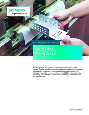
Siemens Digital Industries SoftwareSolid EdgeSheet MetalExecutive summaryAn intelligent process-specific sheet metal environment is availablethrough Siemens Digital Industries Software’s Solid Edge suite. Solid EdgeSheet Metal is the industry’s most advanced sheet metal solution. Thiswhite paper describes how you can leverage Solid Edge with synchronoustechnology and Solid Edge Sheet Metal to speed design time and streamline manufacturing.siemens.com/plm
White paper Solid Edge Sheet MetalContentsIntroduction. 3Meeting the challenge of sheet metal design. 4Challenges of sheet metal design. 4A new approach in sheet metal design. 5A complete and automated 3D sheet metal solution.6Developing 3D sheet metal models with fewor no commands. 6Improved methods for making design changes. 7Re-using supplier and legacy 3D designs. 8Usability balanced for experienced 2D and 3D users. 8Advanced sheet metal features. 9Built-in design validation. 10Documentation and manufacturing support. 11Flat pattern development. 12Conclusion. 14Glossary. 15References. 16Siemens Digital Industries Software2
White paper Solid Edge Sheet MetalIntroductionIf your company designs sheet metal parts, it faces aseries of unique challenges. Although parts are typicallydesigned in their “formed” state, they begin as a flatplate. As a result, manufacturability becomes a criticalaspect of every feature making up the finished part.Add to this the need to account for material thickness,along with bend and corner relief, miter deformationfeatures and critical dimensions (inside or outside).When you take all of this into consideration, it becomesobvious that you need a highly specialized set of tools ifreal productivity and quality gains are to be realizedfrom design through manufacturing.Siemens Digital Industries SoftwareThis white paper discusses how careful consideration ofthe sheet metal process, as well as extensive researchinto the use of sheet metal components, led SiemensDigital Industries Software to develop Solid Edge SheetMetal, the industry’s most advanced set of sheet metalmodeling capabilities.The Solid Edge sheet metal environment is a coredesign capability that includes an entire designthrough-fabrication workflow and streamlined modeling commands tailored to the unique needs of sheetmetal design. As result, Solid Edge Sheet Metal helpsensure that designed parts can be manufactured, documented and utilized by CNC machinery.3
White paper Solid Edge Sheet MetalMeeting the challenge ofsheet metal designChallenges of sheet metal designBefore we take a close look at how Solid Edgeapproaches sheet metal design, let’s first understandwhat engineers struggle with when choosing a 3Dsystem for sheet metal design. Most traditional 3D CAD systems are history-basedsystems that require special commands and workflows to create even simple parts. Typically, usersneed specialized training, which can result in downtime during adoption. While designing sheet metal parts in traditional 3DCAD is faster than 2D, these history-based systemsforce users to preplan designs to accommodate futurechanges. Unless models are carefully constructed,some edits can’t be made without starting fromscratch. Engineers migrating from 2D may not be awarethat a process change is required when moving to atraditional 3D CAD system. Since in-house edits can’tbe made to imported data, supplier change fees canresult.Siemens Digital Industries Software Some productive modeling methods in 2D simplycan’t be duplicated in traditional 3D. This forces newusers to learn steps that are less efficient. The sheet metal command sets of many CAD programs lack depth, leveraging generic design tools forsheet metal design. This requires you to use workflows, commands and features more appropriate formachined, cast or molded parts. Designers don’t have access to design validation toolswhile designing sheet metal components. This canlead to unmanufactureable parts or parts that breakdesign rules (sensors and analysis). With respect to documentation and manufacturingsupport, current working drawings don’t reflect theentire sheet metal process, such as bend tables andflat patterns. Also since the shop floor cannot takeadvantage of manufacturing data present in 3Ddesigns, this can lead to a disjointed process, oftenrequiring the use of separate applications.4
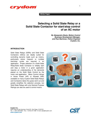
White paper Solid Edge Sheet MetalSynchronoustechnology'HVLUDELOLW\ LVWRU\ LPHQVLRQ GULYHQ3URFHGXUDOIHDWXUHV ,QIOH[LEOH ZKHQFKDQJHV RXWVLGHGHVLJQV DUH QHHGHG LJKO\DXWRPDWHG/LYH 5XOHV6ORZ IUDJLOHHGLWV RQ PDQ\ IHDWXUHG SDUWVFeaturebased'ULYLQJ 'GLPHQVLRQV0RUH )OH[LEOHHGLWLQJ)DVW HGLWVZLWK PDQ\IHDWXUHG SDUWV(DV\ WR XVH GLUHFWLQWHUDFWLRQ([SOLFLWPRGHOLQJ)HDWXUHOHVV/LWWOH GLPHQVLRQ GULYHQ HGLWLQJ /LWWOH GHVLJQDXWRPDWLRQ7HFKQRORJ\Figure 1: Defining synchronous technology.1A new approach in sheet metal designSolid Edge with synchronous technology enables youto resolve these key issues. It might be best to start bydescribing how synchronous technology differs fromother modeling technologies and explain why SolidEdge is more efficient.Before Solid Edge with synchronous technology, therewere primarily two 3D modeling technologies – historybased or traditional modelers and explicit modelingsystems. History-based modelers use a feature-basedapproach to create and edit a model. In addition, sincethey generally are dimension driven, their automatedmodel changes are reliable and predictable. However,achieving any predictability requires a lot of preplanning. Unforeseen changes usually require failedfeatures to be fixed or parts to be remodeled.Siemens Digital Industries SoftwareAlternatively, there are history free modeling systems,which are sometimes called explicit modeling systems.These featureless systems offer little in terms of automated design capabilities with dimensions or relationships. But, they are fast and flexible and can accommodate a wide variety of changes, assuming that theirproprietary geometry kernels can handle suchmodifications.Solid Edge with synchronous technology incorporatesthe best of both worlds by combining the speed andflexibility of explicit modeling and the precise control ofparameterized design. This technology is found in theSolid Edge part and assembly solution. Solid Edge withsynchronous technology is ideally suited to sheet metaldesign. At this point, the white paper will take a closerlook at the main features that Solid Edge with synchronous technology provides to solve the typical sheetmetal problems outlined earlier.5
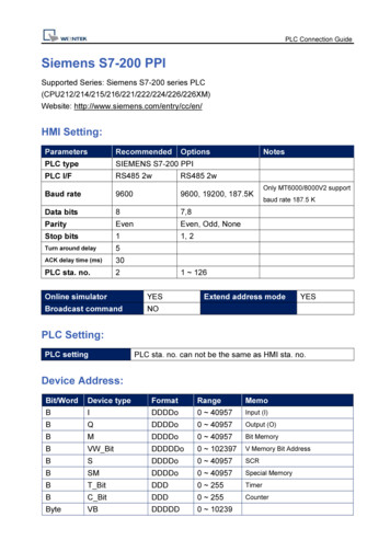
White paper Solid Edge Sheet MetalA complete and automated 3D sheetmetal solutionDeveloping 3D sheet metal models with fewor no commandsDirect interaction paradigm To speed the development process, users can drag 2D sketches directly into a3D model using grab and go tools. Special handles(available through the system’s steering wheel) aredisplayed on geometry such as faces or regions. Thesehandles let users drag these elements into new features, as well as enable them to modify existing parts.Regions are automatically created from imported drawings, which speeds model development. Users can drawsketches in space or on a face for immediate use to addor remove sheet metal material. The steering wheel isdesigned to work with sheet metal parts – so thicknessfaces can get extended, bend radii can get changed andflanges can get pushed in, out or rotated even if cornertreatments are applied. These capabilities are especiallyvaluable since it’s been proven that fewer commandsresult in fewer steps – and fewer steps are directlyrelated to a faster design process.Figure 2: Grab and go design.2History-free, feature-based modeling The heart of fastsheet metal modeling is facilitated by the Solid Edgeability to store features in a collection – instead of in alinear feature tree that traditional CAD systems use.Linear feature trees force a specific edit order andrequire model regeneration during any change. Withsynchronous technology, features are no longer dependent on each other. This enables you to organize andedit your features as fast as you move your mouse. Theability to collect features allows reordering, groupingSiemens Digital Industries Softwareand sorting by name or type. You can easily groupholes, rounds or cutouts together regardless of whenthey were created. You can even reorder holes to thetop of the collection. Features can be selected, edited ordeleted with no performance penalty from modelregeneration.Figure 3: Feature collections in synchronous technology.3Sheet metal-based procedural features Some specialized sheet metal capabilities let you create featuresusing sketches and engineering parameters and makeedits by adjusting those same input parameters.However, unlike history-based systems, unrelatedgeometry and even downstream operations are notregenerated. Features such as tabs and flanges are bestedited using the resulting geometry. However otherfeatures, such as holes, dimples and louvers, are bestedited using the original parameters. This enables youto establish, maintain and edit design intent withoutexpensive model regeneration.Figure 4: Specialized sheet metal features.46
White paper Solid Edge Sheet MetalImproved methods for making design changesLive Rules Synchronous technology provides a powerfulcapability called Live Rules, which enables engineers toget predictable changes with or without constraints.Specifically tuned for sheet metal design, Live Rulesautomatically find and maintain geometric conditionsduring a drag or dimensional edit. Critical model parameters, such as thickness, bends and relief, are maintained during an edit. Other conditions – such as concentric, tangent, symmetric, horizontal, vertical andeven co-planar conditions – are kept during edits.Intelligent models can be developed even if no relationships are used during the creation process. Live Ruleseliminate the need to apply complicated geometricrelations while establishing design intent.Figure 5: Live Rules.53D Driving Dimensions Unlike traditional CAD systemswhere dimensions can only drive their sketch elements,Solid Edge 3D Driving Dimensions can be added to anypart of a 3D model, allowing you to drive critical insideor outside dimensions to establish rules as and whenthey are known. 3D Driving Dimensions allow edits andcan be locked to preserve critical distances. They alsocan be used in formulas with other dimension or linkedto spreadsheets to take advantage of engineeringcalculations.Figure 6: 3D Driving Dimensions.6Nearly instant edit performance Synchronous technology’s most significant difference is manifested by itsindependent features. Historically, traditional CADsystems force changes in one direction – down the treein the order of creation, which regenerates all unrelatedfeatures. Obviously, this restricts a user’s ability to makemodifications since some features may need to becontrolled by different operations. A classic example iswhere a flange needs to be moved while the distance topreviously created flange has to be preserved. Historybased systems force change to the parent feature,which eventually updates the location of the flange.With synchronous technology, engineers can edit thelatter flange and drive the location of the previouslycreated flange. Unrelated geometry is not regenerated,which facilitates faster model performance. By adoptingan independent feature design, users can edit the firstoperation as fast as the last.With direction control, a value change can move eitherof the dimensioned elements, giving you the ability tocontrol the position of geometry that was created earlier in the process. 3D model constraints can also beused to modify geometry making elements perpendicular, tangent or parallel; that relationship can be saved toretain these rules. Again because features and geometry are no longer dependent on each other, users canchange either element and the other will react accordingly regardless of creation order. These capabilitiesenable engineers to make unplanned changes andestablish rules when they are known.Figure 7: Independent feature design.7Siemens Digital Industries Software7
White paper Solid Edge Sheet MetalRe-using supplier and legacy 3D designsEdit supplier or legacy sheet metal designsTraditional CAD systems have always fallen short whenit comes to editing supplier data. Most systems canopen parts and assemblies and use them in designs –but the data can’t be changed easily (or often times,not the way you require). Solid Edge with synchronoustechnology has the unique ability to take importedsheet metal model files and convert them to usableparts where edits can then be made. Key parameters,such as thickness, will be recognized as well as bends.Users can convert cutouts on flat faces or across bendsto a procedural feature, allowing edits to the feature’ssketch. Being able to edit imported data helps reducesupplier change fees as edits to outsourced data can bemade in-house.Migrate 2D to 3D Many companies moving to 3Dalready have a wealth of 2D drawings. Solid Edge is ableto maintain these drawings while also enabling you toutilize them as you make your transition to 3D. TheCreate 3D feature allows you to choose 2D drawingviews and have them automatically orientated in 3D soyou can quickly start modeling. As 3D geometry is created, 2D dimensions are retained during the transitionas editable 3D Driving Dimensions. Whether youmigrate from AutoCAD, ME10 or even DXF, certain 2Ddimensions automatically become editable 3D DrivingDimensions. Those dimensions can be locked to preserve values, linked to other dimensions through equations and even controlled through a spreadsheet. SolidEdge preserves your 2D drawing investments, whileenabling you to realize immediate value from the moveto 3D.Figure 9: Migrating 2D dimensions to 3D.9Figure 8: Editing imported data.8Edit any model as if it was native geometry In orderto work effectively with imported data, as well on foreign parts, all operations must be able to work equally.Solid Edge with synchronous technology, lets you continue design and make edits as if the parts were nativegeometry. You can drag sheet metal tabs or flangeswith powerful grab and go handles and get predictableresults from Live Rules. Live Rules find and maintaingeometric relationships even on imported models.Precise control with 3D Driving Dimensions can beadded to completed models and these dimensions canbe saved with the model. You no longer need toremodel parts just to edit supplier data. You can eliminate change fees and lengthy turnaround times.Siemens Digital Industries SoftwareUsability balanced for experienced 2D and 3D users3D fence stretching Moving flanges, cutouts or entireregions of a model is as easy as doing a stretch in 2D.Simply snap to a desired view – such as top, front –draw a fence around part of a 3D model and drag it intoa shape. You cannot effectively edit in a history-basedsystem because only single features can be edited atone time. During a 3D stretch in Solid Edge, key geometric conditions are maintained with Live Rules. 3DDriving Dimensions are used to control fit and positionso that inside and outside conditions will be maintained. The process is as easy as 1-2-3. You can open apart or assembly, draw a fence and drag it into a shape.This editing process significantly reduces training costsand decreases downtime while moving to 3D.8
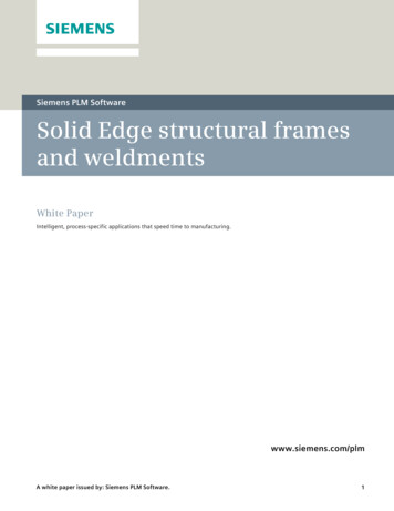
White paper Solid Edge Sheet MetalAdvanced sheet metal featuresThe command sets of many CAD systems lack depthThey only provide generic design tools for sheet metaldesign, forcing you to use workflows, commands andfeatures that are more appropriate for machined, castor molded parts. Solid Edge specialized sheet metaldesign capabilities deliver significant productivity gainscompared to general-purpose CAD tools. Solid Edgeprocess-specific commands and structured workflowsspeed your ability to model sheet metal parts. Built-inintelligence saves additional time by automaticallycalculating material treatments and validating parts formanufacturability. In addition, manufacturing-ready flatpatterns help to eliminate scrap and rework. The resultis faster time to manufacturing, backed by improvedquality of your sheet metal components.Figure 10: Leveraging familiar 2D editing techniques.10Live Sections for 2D section editing Live Sections havealso been applied to sheet metal. You can simply cut asection view through any part of the model and edit theresulting 2D cross section directly. You can add LiveSections from virtually any view and change parts fast.Live Rules maintain critical conditions (such as horizontal and vertical flanges) co-planar faces and materialconditions (such as thickness and bends). Dimensionscan be added to the 2D elements of a Live Section andlocked to preserve critical distances of its 3D counterpart. The process is as easy as 1-2-3. You can open apart or assembly, draw a fence and drag it into a shape.This unique capability enables you to better visualizeand address interferences between parts as easily in 3Das you did in 2D.Intelligent sheet metal features Solid Edge SheetMetal addresses the unique challenges of working withsheet metal parts. When cutouts or holes lie across abend, a traditional cutout command would result innonperpendicular faces. In contrast, the Solid Edgenormal cutout command helps you create accurateperpendicular faces, reflecting the fact that the featurewould likely be manufactured while flat, and thenfolded.Figure 12: Deformation features.12Figure 11: Live sections.11Siemens Digital Industries SoftwareDeformation features, such as louvers and beads, areconstructed by using a single, linear element and simplydefining height and depth and deciding whether youwant the louver ends formed or lanced. With theseassociative feature parameters, you can easily makestyle changes, such as changing a lanced-end louver toa formed-end louver. A more generic CAD approach –such as using library features – would often force you tostart over.9
White paper Solid Edge Sheet MetalDefining part properties The part properties tab on theoptions dialog box enables you to set up the sheetmetal properties for the part you are constructing.These properties are copied to the variable table andused each time you create a new feature. For example,when you construct a flange, the material thickness andbend radius are automatically applied.If you edit these values later, the part will update. Forexample, if the material thickness for the part needs tobe increased, you can edit the value for the materialthickness and the material thickness for the entire partwill change.Figure 13: Material property definition.13Built-in design validationEnsuring manufacturability Model validation isanother area where Solid Edge is unmatched. A classicmanufacturing issue involves cut-outs or flanges placedtoo close in proximity to other cutouts or bends.Typically, there is a minimum distance between bendsthat must be maintained to accommodate the bend die.Designers are aware of this but often don’t measureeach bend for validation. Solid Edge includes designsensors that handle this operation automatically. Othersensors can be used to help calculate cost, variables,surface area and other factors. A custom sensor capability is available if you need more options.Solid Edge enables you to flatten and rebend sheetmetal models, automatically calculating bends fromstandard or custom formulas. In addition to effortlesslycreating an accurate pattern for manufacturing, thissimplifies the modeling of cutouts and holes that lieacross bends.Siemens Digital Industries SoftwareFigure 14: Sheet metal sensors.14Simulation Solid Edge provides scalable finite elementcapabilities that can be seamlessly upgraded as yourrequirements grow. These capabilities includeSimulation Express (included with Solid Edge Classicand Solid Edge Premium) and Solid Edge Simulation(included with Solid Edge Premium or available separately as an add-on for Solid Edge Classic), which areaimed at design engineers and fully embedded withinSolid Edge. Full Simcenter Femap software, a standalone product that offers advanced capabilities foranalyst engineers, also is available. By using simulationat the design stage, designers can turn escalating customer demands into highly demanded products.Simulation enables designers to reduce the need forphysical prototypes, which brings significant time andcost savings. Savings can also be gained by using simulation to increase product quality, which reduces product failure and costly recalls. Design optimizationensures that designs are as efficient as possible byminimizing material and weight, while overall simulation promotes design innovation by producing objectiveresults.Solid Edge simulation includes several capabilities thatare relevant to sheet metal design. Using a normal 3Dfinite element mesh approach to analyze extremely thincomponents in relation to their length (such as sheetmetal components) is extremely resource intensive; italso yields inaccurate results. In contrast, Solid Edgeuses 2D “plate elements” to analyze an automaticallyextracted sheet metal mid-surface, which delivers fastand accurate results.10
White paper Solid Edge Sheet MetalWhile 2D has served many users well over the years andcontinues to allow you to create or maintain existing 2Ddrawings, the fastest way to 2D is to start with a 3Dmodel. As you work in 3D, you only create designdetails once. When your design is ready, you can create2D orthogonal projections, isometric projections, detailand auxiliary views and other perspectives at will. Theseassociative drawing views automatically update toreflect any design modifications to the 3D model, whilethe Solid Edge Dimension Tracker notifies you whendimensions, annotations or model-derived table entrieshave changed.Figure 15: Simulation capabilities.15Components that operate at high speed can start resonating at particular speeds (RPM) or frequencies (Hz),which can lead to catastrophic failure. This is hard topredict and often unrecognized until the machine isoperational, resulting in costly consequences. The ability to predict the four major natural (modal) frequenciesof a given component makes Solid Edge a practicalsolution for engineers who want to solve real problemsearly on at the design stage.In addition, a Stress Wizard is available to take advantage of the Solid Edge “simplified parts” concept, whichignores design details that are not important to theanalysis. Use of the wizard enables users to obtainaccurate results in less time.Documentation and manufacturing supportHighly productive 2D drafting Solid Edge streamlinesdrawing creation with the industry’s most productivedrafting system. Formed and flattened components canbe detailed, dimensioned and associatively retained sothey automatically update when your designs change.Innovative tools for shaded views, exploded assembliesand detail and section views are quickly created toextend accurate design data into other areas of yourbusiness. Using Microsoft-standard OLE technology(object link and embedding), whole drawings or individual drawing views can be easily re-used in otherdocument types, such as Word, Excel and PowerPoint(or any other document that supports OLE), to illustratemanuals, technical specifications, brochures and otherkind of publications.The paperless office has been promised for some time.Although this is technically possible with today’s SolidEdge design and collaboration tools, 2D drawings arestill widely used by many companies that design theirown products and want to relay manufacturing detailsto the shop floor or third-party manufacturing shops.Siemens Digital Industries SoftwareFigure 16: Solid Edge drawing capabilities.16If more detail is required, additional views can be subsequently placed by “peeling” brand new orthogonal andisometric views from others already present. You canalso use Solid Edge to create accurate section and highscale detailed views that include machining symbols,GD&T, bill of materials and auto ballooning. All of thiscan be created to comply with internationally recognized standards, including ISO, ANSI, DIN, JS, Russianand other established conventions, allowing you toestablish fully production-ready drawings in Solid Edge.Working in 3D enables you to realize additional downstream benefits as models move past the design stage.For example, hole tables and coordinate dimensioningensure that you represent your parts in the best possible way for customers and manufacturing.Manufacturing support Solid Edge Sheet Metal excelsat providing highly flexible manufacturing support.There is a thin line between sheet metal design andmanufacturing responsibilities, more so than in mostdesign disciplines. The size of your company oftendetermines where the designer leaves off and the production engineer takes over – as well as whether manufacturing fabrication takes place in house or is subcontracted out. Many times, the design engineer has to11
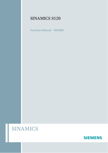
White paper Solid Edge Sheet Metaldecide how specific components need to be made.Siemens Digital Industries Software recognizes that thisscenario will vary from company to company. Solid EdgeSheet Metal maximizes flexibility by enabling you to usethe same data to complete manufacturing support ateither the design stage or the manufacturing stage.Flat pattern developmentSolid Edge standard formula for calculating accurateflat patterns The neutral factor (or K factor as it issometimes known) can be changed to suit specificmaterials, for example, 0.5 for mild steel, 0.33 for aluminum and 0.6 for stainless steel. The formula used inSolid Edge is standard throughout the sheet metalindustry. Solid Edge uses the neutral factor, bend radiusand bend angle to calculate the plastic zone length(PZL).Figure 17: Flat pattern development.17Folding sheet metal can be as much of an art as it is ascience. In theory, all of the above is true and in 99cases out of 100, the standard formula produces excellent results. However other factors outside of the designsoftware can influence the bend characteristics duringmanufacturing. On single bends, this is not as apparent.However, a part with many bends can reflect incremental errors, where at least one of the dimensions can beway out of tolerance.Custom formula Many sheet metal engineers whobend components have bend tables they have developed over time through trial and error. Solid Edge canuse these tables to override the standard formula withsample test data from manufacturing. Solid Edge provides four examples under its “custom” directory. If thestandard default formula does not yield the results yourequire, you can set up a manual override by definingyour own custom formula and specifying that it be usedto calculate the flat pattern size. You can use the threemethods below to establish formulas for working withflat pattern data.Siemens Digital Industries Software1. Designers can develop an accurate and associativeflat pattern for 3D part files and save it in a separatedata stream without having to manage a separatefile. The flat pattern reports the maximum blank sizefor unfolded components, which can be linked to asensor that will issue a warning if the raw materialsheet size is too small. Product markup information(PMI) also can be added to the flat pattern, includingdimensions, notes and GD&T symbols. Flat patternssaved with 3D designs can be used to create accurateflat patterns on 2D drawings as well.Figure 18: Saving flat patterns with the designed part.182. You can create flat patterns on 2D drawings that areassociative to the model. In this case, model changesare reflected in the flat pattern and subsequentlyupdated on drawings, ensuring that the latest flatpattern design modifications make it to the manufacturing stage. While it possible to place stacked orstring dimensions, it is more common on flat patternsto provide ordinate dimensions from a commondatum. Typically, 2D drawings are used for manualprogramming or saved as DXF for machine code.3. You can use “save flat as DXF’” and flat pattern generation commands to create a CAM-ready flat patternDXF file directly from the sheet metal model withoutcreating a drawing first. This approach is useful whena one-off job needs to be performed quickly, such asduring the prototype stage or when machine operators need to rapidly program a CNC machine. Sincemany machines read DXF directly, this approach isquicker, more convenient and less error prone whenmanually reading drawings.12
White paper Solid Edge Sheet MetalThese capabilities play a significant role in enablingSolid Edge to automate perhaps the most widely usedworkflow – the workflow for creating manufacturingready files. When a flat pattern is generated, Solid Edgeautomatically combines collinear lines into a single line.Options are provided to convert spline-based curvesproduced by corner relief into lines, using a suppliedtolerance. The settings are used for all flat pattern generation methods and are intended to provide anNC-ready flat pattern for downstream manufacturing.Users can automatically add corner treatment to prevent dwell burning that can be caused by laser manufacturing machines.Bend tables Like flat patterns, bend tables can bestored with 3D sheet metal parts and p
the sheet metal process, as well as extensive research into the use of sheet metal components, led Siemens Digital Industries Software to develop Solid Edge Sheet Metal, the industry's most advanced set of sheet metal modeling capabilities. The Solid Edge sheet metal environment is a core design capability that includes an entire design-