Transcription
See discussions, stats, and author profiles for this publication at: Coefficient Performance of Battery Running and Charging by MagnetGenerator BediniArticle · March 2018DOI: 10.1115/1.4039504CITATIONSREADS01,0924 authors, including:Uthai SriphanRatthasak PrommasRajamangala University of Technology RattanakosinRajamangala University of Technology Rattanakosin1 PUBLICATION 0 CITATIONS14 PUBLICATIONS 138 CITATIONSSEE PROFILEAll content following this page was uploaded by Ratthasak Prommas on 24 July 2018.The user has requested enhancement of the downloaded file.SEE PROFILE
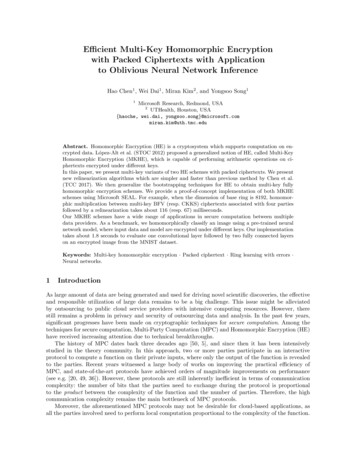
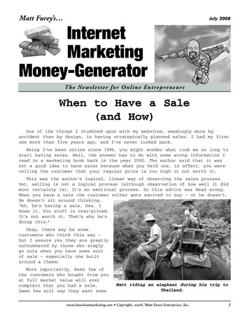
Uthai SriphanRattanakosin College for SustainableEnergy and Environment (RCSEE),Rajamangala Universityof Technology Rattanakosin,96 M 3 Puthamonthon Sai 5,Salaya, Puthamonthon,Nakhon Pathom 73170, ThailandPongsakorn KerdchangRattanakosin College for SustainableEnergy and Environment (RCSEE),Rajamangala Universityof Technology Rattanakosin,96 M 3 Puthamonthon Sai 5,Salaya, Puthamonthon,Nakhon Pathom 73170, ThailandRatthasak Prommas1Rattanakosin College for SustainableEnergy and Environment (RCSEE),Rajamangala Universityof Technology Rattanakosin,96 M 3 Puthamonthon Sai 5,Salaya, Puthamonthon,Nakhon Pathom 73170, Thailande-mail: ratthasak.pro@rmutr.ac.thTika BunnangIntegrate Solution 98 Co., Ltd.,998/27 On-nuch30-32 St. Sukhumvit 77 Road,Suanluang,Bangkok 10230, Thailand1Coefficient of Performance ofBattery Running and Charging byMagnet Generator BediniIn this research study, the performance in battery running and charging of an originalcircuit design is compared with the performance between the developed DC–DC boostconverter running and charging replication circuit design. Bedini generators are a kindof magnetic generator designed by John Bedini on the basis of zero point technology. Thegenerator serves as a self-battery charger. In this study, the two types of circuit design,namely, the original and the replication, are examined in terms of performance in batteryrunning and charging. The DC–DC boost converter offers greater voltage boost capabilities and hence has the potential to enhance step-up power conversions. The novel designwas a prototype of the six-pole eight-neodymium magnet generator, which potentiallyoffers free energy and could therefore serve as an alternative means of addressing energyneeds when the current nonrenewable fuel sources have been wholly depleted in thefuture. The coefficient of performance (COP) for the battery performance of both designsis calculated in this study in order to allow comparisons to be drawn. Upon analysis, it isdiscovered that the DC–DC boost converter circuit is both practical and efficient, offering a high level of step-up power conversion capacity for battery running and charging.The COP of the new system provides a significant increase in COP when compared to theoriginal design. [DOI: 10.1115/1.4039504]Keywords: magnet generator Bedini, Bedini circuit, DC–DC boost converter, coefficientof performance (COP)IntroductionNikola Tesla once said that all people should have energysources for free to fulfill their daily needs. Unlimited quantitiesof electricity are available and would be capable of powering theworld with no need to rely upon nonrenewable fossil fuels suchas oil, coal, or natural gas. The most significant idea is that freeenergy would have no cost. Mechanical energy, which driveswindmills by using the blowing force of the wind, or solarenergy in solar cells, which is converted into DC current andstored in batteries, could be very valuable [1], while other energysources include wind power, water power, and telluric power.This kind of power is produced by free energy generators. Actingagainst this idea is the notion that free energy can be suppressedby corporations involved in the energy sector who rely upon fossil fuels for their profits and do not wish to see alternative energysources thrive. All other remaining untouched forces of natureare familiar in the scientific literature, and include earth batteries,atmospheric electricity, telluric currents, and pressure systemchanges.The Bedini generator is a kind of electrical generator that utilizes the moving parts of working machines to regenerate electricity for other electric devices or to save as back-up power sources.John Bedini is the first person who proposed this kind of1Corresponding author.Manuscript received November 9, 2017; final manuscript received January 17,2018; published online April 12, 2018. Assoc. Editor: Partha P. Mukherjee.generator, called the Bedini Simplified School Girl (SSG) in 2001[1–4], which was then further developed by Peter Lindemann[5,6] and others [7]. The study presents the original basic conceptof a Bedini generator for battery running and charging and alsoexplains the replication design. The charging and running requireperformance inputs and outputs, which exceed normal requirements, thereby implying that radiant energy infusion is involvedin the process [7]. This study is carried out using investigation andanalysis for the two design types of Bedini generators. This willallow the performance to be evaluated and comparisons madebetween the original circuit running and charging Bedini designand the prototype DC–DC boost converter replication by six-poleneodymium magnet Bedini. The study emphasizes the project todevelop the Bedini monopole mechanical energizer six-pole andeight-pole neodymium magnet generators. The test procedure wasestablished to determine the coefficient of performance (COP) forthe original circuit running and charging battery design to compare this with the DC–DC boost converter design [8].The coefficient of performance provides a measure of energytransfer, which is defined by the output as a proportion of theoperator’s input. Coefficient of performance can be applied in thedescription of any machine, which derives additional inputs ofenergy from the surrounding environment. One example would bethe use of COP to explain the details of the energy exchangewhich takes place in solar collectors or in heat pumps [9]. Coefficient of performance differs from mere efficiency in that it can beassigned a value greater than one, as indicated in Fig. 1, whichdepicts energy flow. Indeed, COP typically exceeds efficiency,Journal of Electrochemical Energy Conversion and StorageC 2018 by ASMECopyright VNOVEMBER 2018, Vol. 15 / 041002-1
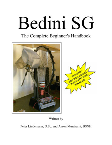
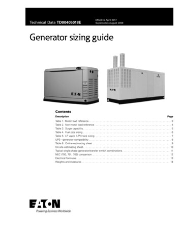
Fig. 1 Block diagram COP used to describe the energy flow of a machinethough would equal efficiency in cases where the input from environmental energy is reduced to zeroCOP ¼2POutPInðOperatorÞ(1)Overview and Design Formulation2.1 Bedini Motor-Generator. From particle physics [8,10,11],it follows that any bipolarity, including any scalar potential, is abroken symmetry in virtual vacuum flow, despite the fact thatinteraction with a vacuum is not considered in classical electrodynamics at the stage of electrical system design. Dipoles asymmetrymeans that it is collecting disordered energy from the vacuum,ordering part of it, and sending it in observable forms in all directions. It follows that any dipole and potential in essence is a negative resistor, which may be used in real circuits. Earlier [12] it wasshown that scalar potential is a composition, consisting of pairs oflongitudinal electromagnetic waves propagating in opposite directions. The potential is an ordered reorganization of vacuum energyto the determinate system of bidirectional energy flows. To attachincreased potential to negative resistance in a battery, for exampleRef. [13], by using the bidirectional property of potential, it is possible to overexcite heavy ions charging the battery and also overexcite electrons, which may feed the load at the external circuit. Thesystem becomes open, and the thermodynamic principle of equilibrium between the electrical system and the surrounding vacuum isviolated and the possibility to work with COP 1 becomes available. A simple DC Bedini motor-generator, which uses only asmall amount of energy for controlling purposes, stores energyfrom the vacuum in a rotor/flywheel and charges batteries or setsof batteries in a nontraditional way. Such devices work withCOP 1.2.2 Bedini Generator Original Circuit Design. Whenever amagnet comes close to a coil, it triggers a current within that coil,which can then pass through the diode bridge rectifier circuit, andalso through the resistor and potentiometer. The current can bestopped if the magnet is placed vertically above the core. If themagnet is then moved past the core, the current is reversed, andflows back through the transistor base and exits via the emitter.This activity causes the transistor to be switched on, which dulyallows the current to flow back from the positive point of the mainbattery to the negative point of the battery via the primary coil.The transistor will switch off after the magnet passes the coil andceases to induce the current in the trigger coil. This causes themagnetic field around the coils to collapse, marked by a041002-2 / Vol. 15, NOVEMBER 2018significant potential spike in the primary coil which passesthrough the charging battery. The basic structures of the originaldesign Bedini generators based on SSG are shown in Fig. 2.2.3 Design Methodology and Development of BatteryRunning and Charging. The principal aim is to develop a circuitfor battery running and charging using the DC–DC boost converter design in the case of a monopole motor. It is also important,however, to improve the performance in battery running as ameans of upgrading the overall circuit efficiency. A monopolemachine has two main components, which include the electroniccircuit and also a running coil which serves as a trigger for introducing the charge to an electromagnetic circuit, which then converts this electrical energy into mechanical energy; the processalso works in reverse whereby mechanical energy can be switchedto an electrical form (Figs. 3, 4(a), and 4(b)). The proposed system thus comprises a monopole machine, which is able to performbattery charging along with battery running and charging todevelop a circuit design. The next component is the stator, whichis a coil that has four windings: here is a power coil winding, atrigger coil, and then a double coil, which serves as the chargingcoil and running coil and which was originally developed to support the DC–DC boost converter circuit voltage booster and current booster. This allows the output voltage to be increased to alevel where it can be usefully applied in battery running andcharging coil winding, which in turn works with the DC–DC boostconverter circuit voltage booster and current booster to increasethe input voltage. Eight permanent magnets make up the rotor andare arranged so that the ends with the same polarity are fixed inthe central spinning plastic disk. Variable flux is created in thecoil by the rotor, but this does not influence the overall performance. A plastic rotor is employed in order to eliminate the possibility of electromagnetic interference upon the steel bearings andshaft, which would be used in a metal rotor. One further advantage is that the rotor weight is reduced, thereby allowing the rotorto revolve more smoothly.2.4 DC–DC Boost Converter. DC–DC converters havetoday become commonplace in the field of switched mode powersupplies. They are typically employed for stepping up or downany kind of nonregulated DC input voltage. A number of differentDC–DC converter types are currently in existence, includingbuck, boost, buck–boost, Cuk, and the full bridge converter. However, for basic converter topologies, only buck and boost can beincluded in this category, with other listed types being derivativesof these two basic converters. For each of the differing convertertopologies, the principles of operation will be unique, as will thespecific benefits and drawbacks each can bring [14].Transactions of the ASME
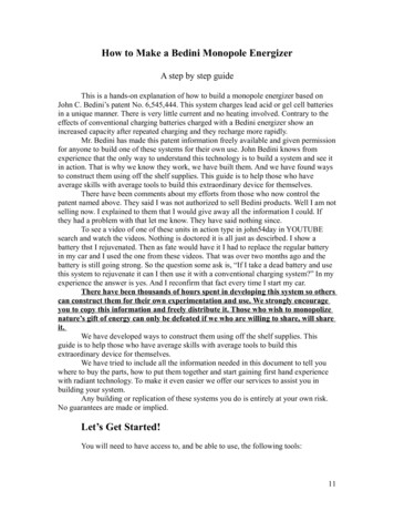
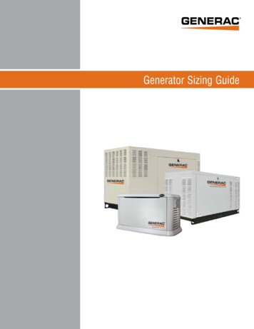
Fig. 2 Schematic circuit original of the Bedini magnet generator monopole machineFig. 3 Prototype of Bedini six-pole and eight-pole neodymium magnet generatorsJournal of Electrochemical Energy Conversion and StorageNOVEMBER 2018, Vol. 15 / 041002-3
Fig. 4 (a) The circuit for the development of a DC–DC boost converter capable of battery running and charging and (b) the block diagram presenting the development of the DC–DC boostconverter for battery running and charging2.5 Design of the DC–DC Boost Converter. The role of aboost converter is to step up the unregulated DC input voltage in systems designed to use renewable energy so that a greater output voltage can be maintained, since this is a requirement when batteries areinvolved. Boost converters are therefore designed with the principal041002-4 / Vol. 15, NOVEMBER 2018focus upon output power achieved, overall efficiency, and practicalease of implementation.Boost converters are used in systems, which involve powertransmission from wind and solar power generators. They absorbenergy and then inject this energy into batteries or other loads.Transactions of the ASME
Fig. 5Representation of the electrical equivalent circuit of the DC–DC boost converterFig. 6 The equivalent circuit of the boost converter during ton in mode 1Fig. 7The equivalent circuit of the boost converter during toff in mode 2Four components within the converter are necessary in order toaccomplish this transmission: the inductor, the diode, the outputcapacitor, and the electronic switch. An illustration of the boostconverter connection appears in Fig. 5 [15]. A switching cycle isnecessary to achieve the activity of energy absorption followed byenergy injection. The mean voltage of the output thereforedepends upon the on/off duration of the switch. When the frequency of switching is constant, any alteration of the on/off duration is known as pulse width modulation switching. The term kdenotes the switching duty cycle, which can be defined as a ratiowhereby the “on” duration is divid
John Bedini is the first person who proposed this kind of generator, called the Bedini Simplified School Girl (SSG) in 2001 [1–4], which was then further developed by Peter Lindemann [5,6] and others [7]. The study presents the original basic concept of a Bedini generator for battery running and charging and also explains the replication design. The charging and running require performance .