Transcription
How to Make a Bedini Monopole EnergizerA step by step guideThis is a hands-on explanation of how to build a monopole energizer based onJohn C. Bedini’s patent No. 6,545,444. This system charges lead acid or gel cell batteriesin a unique manner. There is very little current and no heating involved. Contrary to theeffects of conventional charging batteries charged with a Bedini energizer show anincreased capacity after repeated charging and they recharge more rapidly.Mr. Bedini has made this patent information freely available and given permissionfor anyone to build one of these systems for their own use. John Bedini knows fromexperience that the only way to understand this technology is to build a system and see itin action. That is why we know they work, we have built them. And we have found waysto construct them using off the shelf supplies. This guide is to help those who haveaverage skills with average tools to build this extraordinary device for themselves.There have been comments about my efforts from those who now control thepatent named above. They said I was not authorized to sell Bedini products. Well I am notselling now. I explained to them that I would give away all the information I could. Ifthey had a problem with that let me know. They have said nothing since.To see a video of one of these units in action type in john54day in YOUTUBEsearch and watch the videos. Nothing is doctored it is all just as descirbed. I show abattery thst I rejuvenated. Then as fate would have it I had to replace the regular batteryin my car and I used the one from these videos. That was over two months ago and thebattery is still going strong. So the question some ask is, “If I take a dead battery and usethis system to rejuvenate it can I then use it with a conventional charging system?” In myexperience the answer is yes. And I reconfirm that fact every time I start my car.There have been thousands of hours spent in developing this system so otherscan construct them for their own experimentation and use. We strongly encourageyou to copy this information and freely distribute it. Those who wish to monopolizenature’s gift of energy can only be defeated if we who are willing to share, will shareit.We have developed ways to construct them using off the shelf supplies. Thisguide is to help those who have average skills with average tools to build thisextraordinary device for themselves.We have tried to include all the information needed in this document to tell youwhere to buy the parts, how to put them together and start gaining first hand experiencewith radiant technology. To make it even easier we offer our services to assist you inbuilding your system.Any building or replication of these systems you do is entirely at your own risk.No guarantees are made or implied.Let’s Get Started!You will need to have access to, and be able to use, the following tools:11
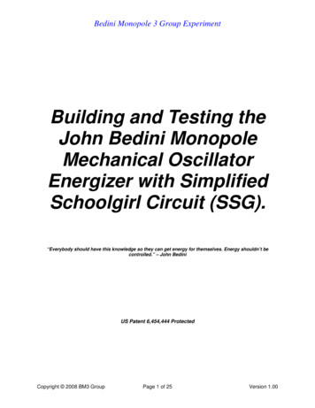
Electric drill for making holes and driving screwsMeasuring tapeSoldering iron½ in open end wrench or medium to small crescent wrenchHack sawRadial or skilsawHot melt glue gunA pair of heavy duty wire cutters or tin snipsNeedle nose pliers (if you have a strong grip this can also be the wire cutters)A volt/ohm meterMasking tape and electrical tapeHere is a diagram of what you will be building. We call it a Kitty Hawk versionbecause it is just the beginning of your adventure into radiant energy use.There are 5 main parts to this device. They are the coil, the rotor, the circuit, theconnecting wires and the base to hold them all together.This is a picture of an expanded version we call the Cactus Express.This model has an amp meter attached which is not part of the kit.22
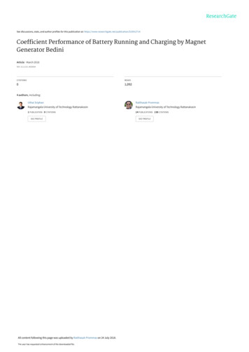
Here is an overview of the 5 parts.The coil is wound with multiple wires all the same length so it is not aconventional transformer. The first coil on the system has 5 wires all about 100 feet long.Any additional coils would have only 4 wires also 100 feet in length. They are wrappedon a plastic spool and the core is filled with cut welding rods. In the picture you see twocoils on either side of the rotor.The rotor is about 5 inches in diameter by 3 ¾ inches long, made of black ABSplastic. It has a place for a bearing in the center. On the outside circumference are placed4 to 6 ceramic magnets which are taped in place. The rotor pictured above has 6 magnets,double stacked.The circuit is the more technical part. But if you have done any circuit soldering itis a simple circuit. If you have never soldered but would like to try, this is a great place tostart. The components are fairly easy to handle and the circuit is not complex. There aretwo circuits shown in the above picture. The circuit has been designed to be expandableso whether the system has one coil or 12 the same circuit works for all.The base is made of a non magnetic material. It needs to be strong enough to holdthe coil and the rotor rigidly in place during the operation. The base of our Kitty Hawk kitis designed for one coil which easily expands to a two coil system. We make the base ofmelamine.33
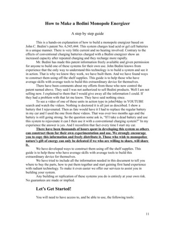
The connecting wires are just wires that go from the battery that powers thesystem and the wires that go to the battery (or batteries) being charged. We put batteryclamps on the end of the wire and it is stripped bare on the other end to fit into the circuitterminal blocks like this.Let’s talk a little about the operation so the connections will be clear. The systemis fed by conventional electricity from a battery or a power supply plugged into the wall.What you are going to build is a specially designed electric motor. The rotor will spinvery fast. But instead of using the mechanical output, we are concerned with tappingradiant energy that is a result of the rapid switching rates of the circuit. As the rotor isgiven a good strong spin the magnets create a voltage in the coil. One of the 5 winds ofwire is used as a trigger sending this voltage to the base leg of the 4 transistors. They allswitch on and the coil becomes an electromagnet. One end of the coil will be north andthe other south. The magnets on the rotor all have the north poles facing out. The coil isconnected so when it is energized the north pole is facing the magnets and it will thenrepel them and the rotor will continue to spin.When the coil repels the magnet it moves away and the voltage in the triggerwinding goes to zero. So the transistor turns off. The current stops and a radiant energyspike occurs. This is seen as a voltage spike as we measure it with our instruments. Butthere is more there than can be measured with a volt meter. The energy then leaves thecircuit through a large diode and makes the charging battery start charging up without anycurrent. Each magnet that comes by repeats the process.So again a magnet comes by inducing a voltage in the trigger winding. That turnson the transistor and the coil is energized. The electromagnet coil now repels the magnetand as the magnet leaves the transistor turns off. The space between each magnet should44
be about 3 but no more than 5 magnets widths apart. This space gives time for the radiantenergy to be captured and determines the percentage “on time” of the transistors.As the rotor gets up to speed the action actually changes so that when the coilenergizes the magnet has past it already. So the coil is now pulling the south pole of thenext magnet towards it. So the spacing is important not to be too small between eachmagnet or else the coil will start repelling the next magnet and slow everything down.So the faster the magnets go past the coil the more pulses of radiant energy hit thebattery and the faster the charge rate. Also each winding on the coil taps a portion ofenergy. So the more windings the greater the flow of energy. If a second, third or 12th coilwere added to pulse the rotor they would all receive their switching voltage from thesame trigger coil. The speed of the rotor increases substantially with each coil. Thegreater the speed the greater the trigger current to the transistors. If you have 4 coils ormore the circuit needs an increase in the resistance to decrease the trigger voltage andcurrent so the energizer doesn’t draw more current than needed for the charging action totake place. But increasing the resistance which is now fixed at 147 ohms doesn’t justslow down the rotor it also makes the whole system consume less input power. If wedecrease it from its present value of 147 ohms on the Kitty Hawk we can decrease thecurrent draw and it will use less power, but we also decrease the charging rate. So for aone or two coil system the 147 ohms is the best balance between current draw andcharging output. I have found that a 6 coil system with an increase of just 22 ohms in thetrigger resistor changes the current draw from 6 amps to 2.5 amps. A one coil Kitty Hawkuses about 1.2 amps current at 12 volts input power. So a little less than 15 watts ofpower.What we offerIf you like what you see but need help building parts of your system send an emailto homenergy1@gmail.com. We will send you a list of how we can help you.55
Now we will show you how you can build each part of your system.The CoilThree items are needed for the coil. They are a plastic spool, the magnet wire and theferrite core.Plastic spool:The plastic spool needs to be 3 to 31/2 inches long and 3 to 3 1/2 inches diameterwith a ¾ inch hole in the middle. Pittsfield Plastic Engineering sells a 5 pound solderspool that is perfect. On the web at www.pittsplas.com to order call 413-442-0067.Here is a photo of a Pittsfield Plastic Engineering 5 pound solder spool (the spool is verylight the solder would weight 5 pounds):Magnet wire: 500 to 550 feet of 18 AWG (gauge) magnet wire for the 5 winding coil.There are a few online sources for this. Here are some:Paramount wire at www.parawire.comMcMaster-Carr at www.mcmaster.comCMS Magnetics at www.magnet4sale.comEssex is a big magnet wire manufacturer. Their Denver number is (800) 774-4643. Theycan direct you to a warehouse nearest you. They sell it in about 10 pound spools.For your planning purposes in this size of magnet wire one pound equals about200 feet. You can also check if you have a local electronics supply store (the kind forprofessionals) they may carry spools of at least 100 feet. A radio shack store doesn't carrythis in the length you'll need.66
The center of the spool will be stuffed with cut welding rods to provide for theferrite or iron based core. The welding rods are copper coated mild steel 1/16th inchdiameter. Welding supply stores have them in 1 pound tubes and they come in 36 inchlengths. Lincoln R60 welding rods work well. R-45 rods from other companies alsowork. You will cut them 3 ½ inches long. Do your best to keep them the same lengthsince it is best to have a flat surface facing the magnets and you be using a file to makethem all flat on one side. To fill the spool center it will take about ½ pounds of cut rods.Coil building:The Kitty Hawk system uses 18 AWG magnet wire. We recommend 100 to 106feet for each winding. The wire comes in large spools and you’ll need to measure out thefive lengths. So you will need at least 530 feet to have enough for all 5 windings. You cantake it outside and stretch out five 106 foot lengths. You can have a hook or a spool 53feet from the spool and then stretch each length back to the spool to get the 106 total.Keep the ends separated from each other so you can have the opposite ends of each wirein two separate bundles. Like so:To keep the wire off the ground so the insulation is not damaged you might drapeit through the back of a chair. Once all five strands are stretched out you need to twistthem together. The twisting provides for better mutual inductance and handling. One turnper inch is sufficient. Once the wires are stretched out this twisting is easily done bytaping the ends together on a wooden dowel. Then place the dowel an electric drill chuckand give it a spin for awhile. Then do the same to the other end. No need to reverse thedrill direction. Some people like a lot of twist in the wires. It is not real critical how muchtwist there is, but it most likely improves performance. It does make handling during thewinding process easier.You will need some strong electrical tape for the winding process. As the wire iswound on the spool it will require constant pressure to keep it even and tight. This willtire your hands. But the instant you let the pressure off, the wire will go very loose andyou’ll lose a lot of work. So to prevent this before you let off the pressure wrap the last77
few turns with about 3 or 4 wraps of electrical tape. You will have to do this at the veryend of the winding for sure.You could mark the ends of each wire length with tape so you’ll know which endsmatch up after all the twisting and coiling. But it is just as easy to use a volt/ohm meter totest them afterward. And yes you need to have a Volt/Ohm meter because you’ll want tosee your batteries charging up. They don’t have to be real fancy. A little digital one onlycosts about 10.Now that the wires are twisted start winding it on the spool clockwise from oneend, but leave about 10 inches of wire not wound on the spool so you can connect it tothe switching circuit. Once the coil is wound you will never be able to pull on those innerwires. So start with 10 inches of wire out of the coil and you can cut the end if it is toolong after the coil is installed.Wind around the spool core from one end to the other and then back again. Ideallynice smooth layers of evenly spaced wire. But most likely you will find yourself withsome gaps and bumps part way through. Don’t worry it will still work. Just fill in thegaps as you go and try to keep it so the wire is evenly distributed along the spool lengthwhen you are done. At the end leave about 10 inches of wire to connect to the switchingcircuit. Try to have the winding end at the same end the other wires are sticking out. Thatway
John C. Bedini’s patent No. 6,545,444. This system charges lead acid or gel cell batteries in a unique manner. There is very little current and no heating involved. Contrary to the effects of conventional charging batteries charged with a Bedini energizer show an increased capacity after repeated charging and they recharge more rapidly. Mr. Bedini has made this patent information freely .