Transcription
Introduction to ERD modelling using UML Class diagrams withMagicdraw (ver 17)Robin Beaumont robin@organplayers.co.uk Tuesday, 04 October 2011Contents:1.Introduction . 21.1.Acknowledgement .21.2.Where to obtain the software .21.3.Before you begin this tutorial?.21.4.What are the aims of this tutorial?.22.The Scenario . 33.Why Use a UML Class diagram to represent a ERD diagram? . 33.1.Differences between UML Class diagrams and ERD‟s .43.2.Starting Up MD/PA .44.Creating and editing a new Project . 54.1.Creating a new diagram .64.2.Drawing .74.3.Creating Classes .84.4.Editing and Adding Attributes .94.5.Defining a Relationship among the Classes .114.6.Completing the diagram .145.Extended Exercise . 146.Useful Tricks and Tips . 156.1.Copying a diagram on the fly to a Word document or other software.156.2.Saving a diagram as a picture.156.3.Linking Diagrams .166.4.Adding Documentation to a Diagram .177.Conclusions for this Tutorial . 178.Appendix - Installing MagicDraw . 18Video of this tutorialYou can see this tutorial as the second and third youtube videos at:http://www.youtube.com/playlist?list PL5D590974B7967000
Introduction to ERD modelling using UML Class diagrams with MagicDraw1. Introduction1.1.AcknowledgementThe original version of this handout, was designed for a similar piece of software (System Architect), and wasdeveloped byDorothy Dologite and Richard Holowczak, at City University of New es/9490/satutorial/ but unfortunately since SA have been takenover by Telelogic there is no longer an educational version of the software. Luckily over the last few years anumber of alternative Case tools have become available, the two most important being MagicDraw and VisualParadigm.1.2.Where to obtain the softwareThis depends on who you are: Students at The Royal College of Surgeons (Edin.) will be provided with a academic licence, whichallows you to use the personal edition. By default you need to download the actual software from themagicdraw site (see below). All others can obtain the software by visiting and registering at: http://www.magicdraw.com/ for thefree community edition. An alternative with a similar interface is Visual Paradigm (VP-UML).1.3.Before you begin this tutorial?Before you work through this tutorial you should have the following knowledge and skills: A basic understanding of systems development life cycles An understanding of the basic terminology used in Entity Relationship Diagrams A working knowledge of Microsoft Windows/ Apple environments including working with multipleapplications and windows, dialog boxes, and so on Preferably some experience with using a Database Management System such as Access, Oracle orBase in OpenOffice/Libreoffice, although this is not assumed in this tutorial.If you feel that you are unable to answer yes to any of the above criteria a good starting point is to workthrough is my Database/ systems modelling course or which this is part see section 8 nts.htmlIn 2009 Magicdraw developed a plugin that allows the drawing of Crows feet notation in class diagrams,however this is not available for the personal edition, if you do have access to this plugin I would recommendyou try it out for this tutorial.1.4.What are the aims of this tutorial?This tutorial is the first in a series to introduce you to using a specific CASE tool, MagicDraw Personal Edition(MD/PA). Because this is the first tutorial it provides you with screen by screen details of what to do. The aimbeing to familiarise you with the most common, basic features of MD/PA. By the end of this tutorial you will feelconfident with navigating around MD/PA and with the basics of drawing Class diagrams. Subsequent tutorialsassume you have this knowledge and therefore provide less detailed instructions.While the complete CASE tool has hundreds of features capable of addressing the complete systemsdevelopment life cycle, this practical chapter will focus only on a small, but important subset that of creating aERD (Entity Relationship Diagram).robin@organplayers.co.ukD:\web sites mine\HIcourseweb new\chap11\case tool tuts\magicdraw\erd1 2007 new.docxPage 2 of 19
Introduction to ERD modelling using UML Class diagrams with MagicDraw2. The ScenarioFor this tutorial we will be using the following scenarioThe business we are modelling is a Travel Agency. In the Agency, a Travel Agent willmake one or more Reservations for a Customer. A Reservation is associated with aparticular Hotel Room at a particular Property and the Hotel room is associated with zeroor more reservations over time (I have highlighted the proposed Entity types/Classes).3. Why Use a UML Class diagram to represent a ERD diagram?In the past I have introduced ERDdiagramming tools then moved ontoUMLdiagrammingtools, whichinvariably has led to confusion and theinability of some students to move ontothe more complex aspects of UML. Inan attempt to avoid this I have decidedto introduce a simplified UML classdrawing technique to allow the drawingof a ERD roughly semanticallyequivalent as a way of demonstrating how ERDs can be created using aUML mindset and also highlight the relationship between ERD‟s and UMLclass diagrams.The relationship between ERD‟s and UML Class diagrams is best shown by comparing the two. Lookingabove there are two diagrams the right hand one uses ERD symbols for the various relations whereas theequivalent UML diagram makes use of UML equivalent symbols for the associations.If you do not understand any of the above please refer to section 11 at ntents.htmlExercise 1UML Association MultiplicityThe multiplicity value of association end A.0 - zero and only zero.1 - one and only one.0.1 - zero or one.0.* - from zero to any positive integer.1.* - from one to any positive integer.* - any positive integer.Simple uml Association multiplicity symbols given above equate to the Cows feet notation used in ERDrelationships. Complete the following table to show the various equivalent :\web sites mine\HIcourseweb new\chap11\case tool tuts\magicdraw\erd1 2007 new.docxPage 3 of 19
Introduction to ERD modelling using UML Class diagrams with MagicDraw3.1.Differences between UML Class diagrams and ERD’sIt is important to realise that UML class diagrams offer far more options („semantic richness‟) than ERD‟s, andalso do not follow some of the conventions of ERDs.ERD entity attributes conventions: Indicate which attributes are Key fields and often include a Unique identifier (ID) field. Display Foreign key fields (attributes) which are often added by the modeller or automatically by ERDdrawing software with the „FK ‟ prefix.In contrast in UML class diagrams: You do not indicate which are key fields (attributes) and do NOT include a unique identifier field foreach instance, which is called an OID (Object Identifier) as this attribute is assumed to exit. You do not indicate foreign Keys (the concept does not exist in uml) but can use a related conceptcalled a qualifier. (I avoid this).These are important differences to keep in mind when moving from ERD to UML class diagrams.For this tutorial we will be accepting the ERD conventions. In other words forcing a UML class diagramto work like an ERD.3.2.Starting Up MD/PAIt is assumed that you have MD/PA installed See appendix 1 concerning installing MDIn this section, the basic techniques for starting up the MD/PA will be described. MD/PA is a Windowssoftware application that runs within the Microsoft XP operating system. As with most Windows applications,starting SA/SE is simply a matter of clicking the left mouse button on the Windows Start menu as shown here:Start the program by going to "Start"menu, selecting (All) Programs, then MagicDraw UMLthen MagicDraw UML by clicking on it as shown below:The magic draw screen will appear.After which you may be asked to check or download variousupdates please select – no. Many of the updates you areoffered are not appropriate for the academic version and youwill just waste time attempting to install themrobin@organplayers.co.ukD:\web sites mine\HIcourseweb new\chap11\case tool tuts\magicdraw\erd1 2007 new.docxPage 4 of 19
Introduction to ERD modelling using UML Class diagrams with MagicDraw4. Creating and editing a new ProjectBefore you can do anything in MD/PA you need to either create a new project or open an existing one. We willcreate a new project which will model the above scenario:We will initially concentrate on the two classes, Travel agent and Reservation.To create the new project Choose the menu option File - New ProjectThen Give the new blank project the name Travel agency and select a sensible project location I typedC:\uml\travel agency and clicked the option Create directory for project.MD/PA then creates and loads the new project:The MD/PA main screen is divided intomain sections:four1. Along the top are the menus and a button / tool bar.2. The Project pane appears on the top left hand side3. Properties paneappears in a smallwindow below it.4. The right handside of the screen,the diagram pane,is reserved todisplayopendiagramsandmodels.All of the detailsfor a particularproject, includingdiagram details,are stored in adatabase which isoften also calledan .ukD:\web sites mine\HIcourseweb new\chap11\case tool tuts\magicdraw\erd1 2007 new.docxPage 5 of 19
Introduction to ERD modelling using UML Class diagrams with MagicDraw4.1.Creating a new diagramThere are several ways to create a new diagram you can either click on the class diagram icon or select themenu option Diagrams - Class Diagrams.Select thediagram.menuoptionDiagrams- classFollow the instructions opposite to create a classdiagram called travel agency.3. Click OKExercise 2Please carry out what I have described above.robin@organplayers.co.ukD:\web sites mine\HIcourseweb new\chap11\case tool tuts\magicdraw\erd1 2007 new.docxPage 6 of 19
Introduction to ERD modelling using UML Class diagrams with MagicDraw4.2.DrawingRemoving the grid from the drawingcanvasThe grid is my pet annoyance! To removeit:robin@organplayers.co.ukD:\web sites mine\HIcourseweb new\chap11\case tool tuts\magicdraw\erd1 2007 new.docxPage 7 of 19
Introduction to ERD modelling using UML Class diagrams with MagicDraw4.3.Creating ClassesOnce you have positioned the new class on the canvas a rather cluttered object appears this is because ofsomething called Smart Manupulation – a feature that the company claims makes using the software easier.Basically each of the dots / icons allow you to add / edit or remove various elements from the class to find outmore go to help - user manual. A similar feature exists in Visual Paradigm called the Resource CentricInterface.robin@organplayers.co.ukD:\web sites mine\HIcourseweb new\chap11\case tool tuts\magicdraw\erd1 2007 new.docxPage 8 of 19
Introduction to ERD modelling using UML Class diagrams with MagicDrawAdding names to classes:4.4.Editing and Adding AttributesTo add / edit attributes simply select the class then click on the relevant bubble.NameData TypeAgent idstringAgent namestringAgency phonestringIn this example, I have added 3 attributes to the Travel Agent entityAlso notice that I have specified what type of attribute each is. If youhave worked with databases you will be aware that data is classifiedinto a number of types, the five basic divisions are:String or Char characters you may also specify how many characters are probably requiredNumbers Integers and real numbersBoolean This type of data is where it can only take one of two values such as Yes/no or open/closed etc.Binary Media such as pictures / audio and movie filesDate/TimeWe will now edit the above attributes to specify exactly what type each is.robin@organplayers.co.ukD:\web sites mine\HIcourseweb new\chap11\case tool tuts\magicdraw\erd1 2007 new.docxPage 9 of 19
Introduction to ERD modelling using UML Class diagrams with MagicDrawSpecifying attribute typesThe picture below shows you how to set the attribute agency phone to type string.The diagram then gets updated to:Repeating the aboveprocess for the twoother attributesresults in:Exercise 3Please carry out what I have described above.robin@organplayers.co.ukD:\web sites mine\HIcourseweb new\chap11\case tool tuts\magicdraw\erd1 2007 new.docxPage 10 of 19
Introduction to ERD modelling using UML Class diagrams with MagicDrawI repeated the above exercise by adding the following attributes and specifying there type in the reservationentity type (class).NameData TypecodecharacterReservation datedateRoom typecharacterResulting in:Exercise 4Please carry out what I have described above.4.5.Defining a Relationship among the ClassesAt this point, two classeshave been defined. Now it istime to link these classes inan association. In thisexample, we will link theclasses with a one-to-manyassociation.Before actually drawing therelationship take a look atwhat the MD/PE‟‟s help filehas to say on the topic of“associations”. You can seethis by opening the helpmenu option Help contentsthen following the detailsopposite. The latest versionof help has moved therequired help shown on theleft to the third of fourthoption down.robin@organplayers.co.ukD:\web sites mine\HIcourseweb new\chap11\case tool tuts\magicdraw\erd1 2007 new.docxPage 11 of 19
Introduction to ERD modelling using UML Class diagrams with MagicDrawAt the bottom of the information a list of the types of multiplicity can be seen – given below to refresh yourmemory.MultiplicityThe multiplicity value of association end A. 0 - zero and only zero. 1 - one and only one. 0.1 - zero or one. 0.* - from zero to any positive integer. 1.* - from one to any positive integer. * - any positive integer.Follow the instructions below to create an association.We can now specify the multiplicities for each end.robin@organplayers.co.ukD:\web sites mine\HIcourseweb new\chap11\case tool tuts\magicdraw\erd1 2007 new.docxPage 12 of 19
Introduction to ERD modelling using UML Class diagrams with MagicDrawSimilarly we know that a particular reservation is only associated with one reservation.And the final resultExercise 5Please carry out what I have described above. Also remember torobin@organplayers.co.ukD:\web sites mine\HIcourseweb new\chap11\case tool tuts\magicdraw\erd1 2007 new.docxPage 13 of 19
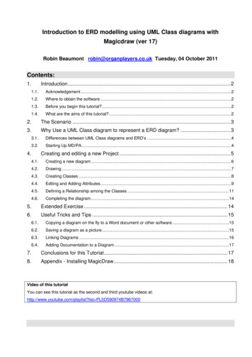
package Data[Introduction to ERD modelling using UML Class diagrams with MagicDraw4.6.Completing the diagramThe completed scenario consists of four Entities(classes) shown opposite.If it were a „true‟ ERD rather than a cross between aUMl class diagram and a ERD we would alsoinclude Foreign key fields (attributes). That is in thereservation Entity type (class) we would have twomore fields (attributes) FK travel agent id andFK room id.SimilarlyroomwouldhaveFK property id.Similarly if this were a correct UML classdiagram, we would not include the Instance(object) IDS such as agent id and property idand certainly not have foreign keys.Exercise 6Inspect the class diagram opposite and attempt toimitate it:hotel booking ]Also remember to save your project.Well done you have nearly finished the first tutorial. However there are some very important administrativetasks within MD you need to learn now.5. Extended ExerciseTo give you more practice try the following scenario:A hotel has a single reception.The reception makes use of areceptiondiary1single Diary but the Diary is0.*maintainedbynumerousreceptionists or reservation1forms which can be considered tobe a type of input via thereception for the diary. The Diaryreceptionistreception lates to a single Diary and alsoa single customer. Customers0.*make reservation(s). Customerscan be of two types eitherreserv ation0.*vacationersorcustomerBusiness traveler.Once a1customer who has made areservation actually takes upresidencetheybecomeaHotel guest. One reservationv acationerbusiness travellermay result in zero or moreHotel guest(s) but a Hotel guestalways relates to a singlereservation. Each Hotel Guestowns zero or more Vehicles. A room can be booked by zero or more Hotel guests who can book one ormore rooms.Above is an incomplete solution, three entities/classes are missing. I have also made use of a special type ofrelation/association called generalisation in two places, you can find out about them in MG help or wait untilyou have worked through the introduction to UML section 11.4 at ntents.html or just use ordinary relation/associations for now.robin@organplayers.co.ukD:\web sites mine\HIcourseweb new\chap11\case tool tuts\magicdraw\erd1 2007 new.docxPage 14 of 19
Introduction to ERD modelling using UML Class diagrams with MagicDraw6. Useful Tricks and Tips6.1.Copying a diagram on the fly to a Word document or othersoftware6.2.Saving a diagram as a pictureExercise 7Copy your diagram into a wordprocessingdocument(e.g.Microsoft Word) by using the copyon the fly technique (see above).Then when in the word processor: Attempt to reduce the sizeof the picture by dragging a cornerof it on the page so that it takes upabout a quarter of a page. Copy some text and rightclick on the picture to bring up theformat picture option then selectlayout - square. Notice how thetext now wrapes around it. Go to page setup - orientation to change betweenportrait and landscape mode. Finally read in the wordprocessing help files about creatingcontinuous section breaks so thatyou can create documents withsome pages in portrait and others in landscape orientation. This is important when you have manydiagrams in a document.Mastering these techniques is vitally important to create well presented assignments.Video of thisThis is discussed further on youtube at nplayers.co.ukD:\web sites mine\HIcourseweb new\chap11\case tool tuts\magicdraw\erd1 2007 new.docxPage 15 of 19
Introduction to ERD modelling using UML Class diagrams with MagicDraw6.3.Linking DiagramsSuppose that you have a complex class diagram and have realized that a number of classes are basically anexpansion of one particular class for example in our diagram the Class Property could be associated with anumber of classes such as Customer, Staff, Bill etc. It is possible to link the two together on two separatediagrams:The Property Class on the diagram then indicates the hyperlink:robin@organplayers.co.ukD:\web sites mine\HIcourseweb new\chap11\case tool tuts\magicdraw\erd1 2007 new.docxPage 16 of 19
Introduction to ERD modelling using UML Class diagrams with MagicDraw6.4.Adding Documentation to a Diagram7. Conclusions for this TutorialIn this tutorial, you have learnt the basic steps for creating and manipulating a simple UML class diagramwhich can be considered to be similar to an ERD diagram. Because the MD/PE product was not designed forthis purpose you may have been confused by the many options that you did not make use of but at the sametime it did expose you to the software. Moving on to UML will provide you with an opportunity to make use ofmany of these options and discover the richness of UML.Robin Beaumont Monday, Tuesday, 04 October 2011robin@organplayers.co.ukD:\web sites mine\HIcourseweb new\chap11\case tool tuts\magicdraw\erd1 2007 new.docxPage 17 of 19
Introduction to ERD modelling using UML Class diagrams with MagicDraw8. Appendix - Installing MagicDrawDetails for obtaining Magicdraw are given on page 2.Remember you need the licence/unlock key (in the form of an xml file) saved on your local machinebefore installing MagicDraw. Make a note of where it is.During or after installation you are asked to provide a licence/unlock key. Click on the Select unlock keyoptionYou will then be asked to indicate where the licence/unlock key file is navigate to the correct folder.You will then be asked which predefined Magicdraw configuration you want, Select System Analyst and thenclick OK.You can always change this from the MD menu Options - Perspectives - Perspectives.robin@organplayers.co.ukD:\web sites mine\HIcourseweb new\chap11\case tool tuts\magicdraw\erd1 2007 new.docxPage 18 of 19
Introduction to ERD modelling using UML Class diagrams with MagicDrawIf/when presented with either of the following two dialogue boxes click Cancel.The first screen should then appear, take some time to read through the information about MagicDrawresources.When you have had enough Click on the menu option File - Close all projects. You are now ready to beginrobin@organplayers.co.ukD:\web sites mine\HIcourseweb new\chap11\case tool tuts\magicdraw\erd1 2007 new.docxPage 19 of 19
Start the program by going to "Start" menu, selecting (All) Programs, then MagicDraw UML then MagicDraw UML by clicking on it as shown below: The magic draw screen will appear. After which you may be asked to check or download various updates please select - no. Many of the updates you are